1041 | P a g e
A STUDY ON VIBRATION CONTROLLER AND
SEISMIC RESISTANT CABLE STAYED BRIDGE
WITH MODEL
Bilcilintan Patel
1, Amit Baghel
2, Nikhil Kumar
3Asst. Prof. Pankaj Kumar Singh
4Lovely Professional University, Phagwara, Punjab
School of Polytechnic (Civil Engineering)
ABSTRACT
This work leads the review about the seismic behaviour and different mode of vibration of cable stayed bridge. The system of bridge is more vulnerable toward the seismic resistant which was estimate in San Fernando (1971), Loma Prieta (1989), Northridge (1994), Kobe (1995), and Taiwan (1999) earthquake . With the help of wooden logs, eventually stone and cross beam the first bridge was maked by human in India. After some year with the help of trees and bamboos poles another bridge constructed by “American”. Stronger bridges were constructed by “Mughal” administration in India with using iron and plaited bamboo in the 4th century. A cable stayed bridge can use for long span with different types of pylons like A type, H type, inverted Y type, Single pylon, Diamond or Pyramid shapes & Double diamond or Spread pylon shapes. In our work we have inserted a mechanical device as well as vibration indicator and seismic controller in model. With the help of this model and work we are able to get the information about vibration of bridge and their components when exceeding from their permissible limits of vibration or at the time seismic effects when the forces acting in horizontal direction. For seismic resistant we have maked a mechanical shock absorber in the foundation of bridge, which help in showing good performance under the different intensity of vibration.
Key Word:
Base (foundation)
,
Cable stayed bridge, Deck girder, Pylons, Steel Cable
I. INTRODUCTION
The concept of Cable Styed Bridge with girder which is supported by cable was first introduced in 17th century.
A lot of cable stayed bridge has been successfully constructed with different shape of pylon across the India in
the last decay of 20th and 21th century. After the Second World War a new concept of cable stayed bridge was
developed with including deck which is rested on piers of bridge. In a hydraulic structure if the deck is
supported by a multiple cable that runs from main girder to the tower of bridge is called “Cable Stayed Bridge”.
The compressive force on bridge in the form of dead load and live load is transferred to the tower, tower is
responsible to absorb and transfer these load to the ground effectively and efficiently. In the second half 20th
century cable of cable stayed bridge was designed in such way that it offers more stiffness, strength and stability
1042 | P a g e
to measure the vibration of cable in the bridge. Cable stayed bridge having a strong beam for full span of bridge
with more pillar (tower) in the middle or at end. The advantage of cable stayed bridge is that it most suitable for
the span varies from 200 m to 900 m with free cantilever which provide more stiffness and stability. A cable
stayed bridge constructed by prestressed concrete which is most suitable for high span with long life period .The
demolition of prestressed structure is more hazards, A professional and experience industry feed required for
demolition of cable stayed bridge. If the span of cable stayed bridge will increase then internal force and
displacement along the girder will huge. Both lateral and vertical stability of cable stayed bridge is the important
factor when the span of bridge increases from 400 m (Tang, 1976 and Ermopoulos, 1992).Now the construction
of cable stayed bridge is going to increase day by day due to rapid development and modernization with
availability of different types of construction material .Today following types of cable stayed bridges is going to
use:
(1) A Cable Stayed Bridge
(2) Cantilever Cable Stayed Bridge
(3) Multi Span Cable Stayed Bridge
(4) Extradose Bridge
(5) Cable stayed Cradle- System Bridge
1.1 Component of Cable Stayed Bridge
Figure 1. Types of Cable used in Cable Stayed Bridge
1.1.1Cable
It is composed of one or more than one wire with strand wire system. The cables used in stayed bridge was
maked by thousands of parallel high-strength steel wires with diameter is about 5 mm and the core of the cable
1043 | P a g e
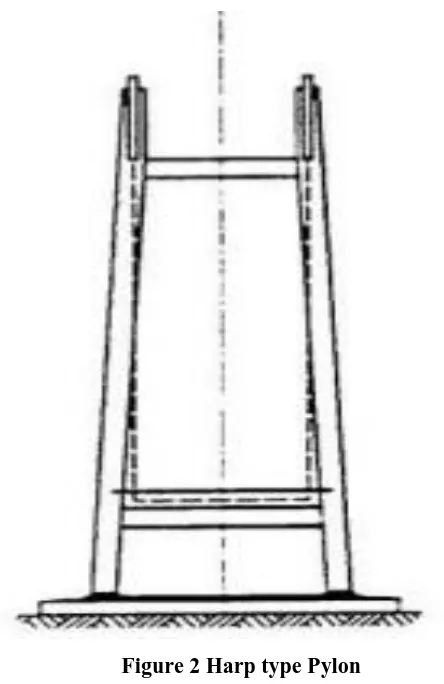
1.1.2 Pylons
It is tower like structure which transfer the load from girder to cable then pylons then ground .In the
model we have used harp types of pylons which giving supported the deck girder of the bridge at the
both end near the approach.
Figure 2 Harp type Pylon
1.1.3 Deck
The deck of the bridge maked by ply wood in our model which is able to take the load due to vibration as well
as dead load.
II EXPERIMENTAL PROGRAM
To analyse the behaviour and stability of cable stayed bridge we have prepared a model with the help of
different shock absorber material which are able to bear the vibration force due to effects of earthquake and a
special take care was taken as per seismic code like IS 4326, IS13920 etc. during the making of foundation so
that vertical and horizontal movement can possible in superstructure and substructure of the bridge which is
providing more stability to bridge during the earthquake. In the foundation we have added a setup of electrical
device by the help of this device we are able take the indication during the vibration of structure when their
1044 | P a g e
2.1 Base with Flexible bearing
In cable stayed bridge model we have inserted a mechanical shock absorber in the form of spring. The lower end
of the pylon is fixed with base and flexible shock absorber acted as intermediate material between base and
pylons of bridge. Due to the flexibility of spring pylons are able to move in horizontal direction as well as
vertical direction.
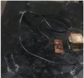
Figure 3 Flexible Base with Electrical Setup
2.2 A setup of Electrical Device:
In the base (foundation) we have fixed a setup of electrical device which
was used to control the intensity of vibration as well as indicator fitted above the pylons. The intensity ofvibration can control by speed controller with the help of this assembly we are able to safe the thousand human
life and loss of economy.
2.3 Seismic and Vibration Indicator:
By the help of this device we are getting three type of indication first
at moderate vibration with “Green light” second at medium vibration with “Yellow light” and third at highvibration with “Red light
” .
2.4 Assembly of cable with Pylon:
In case of field assembly first cable stretched then welded together with
bridge and lifted in position. The strands of wire collectively stressed with the help of hydraulic jack. These1045 | P a g e
III RESULTS AND DISCUSSION
The impact of earthquake on human life and structure like bridge, multistorey building, liquid storing container,
bunker etc . is very poor which was seen in last few years. The main aim of this work to protect structuraldamages and reduce the losses in the form of human, money. Throughout the world a large number of bridges
have been collapsed due to seismic effects, use of poor quality of material, improper layout, vibration effects,
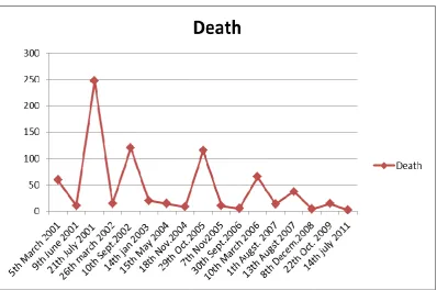
use of less tensile strength of cable etc. The following data showing that the number of bridge collapse due
many reason in India. But these data is based on probabilistic basis this number can increase or decrease.
Figure 4 Number of collapsed bridge (X- axis) and number of death (Y-axis)
The above data showing that the number of collapsed bridge as well as death is decreases when the years
increase because development of technology and good quality of material used.
IV.
CONCLUSION
A lot of investigation contributed toward this work to control the vibration and get their indication when bridge
vibrates more than their permissible limit. This works provides an analysis of the aesthetic and structural and
vibrational properties of the cable stayed section .The increase in span increases the axial tensile force in the
cable. By this work we are able to get the information about vibration of bridge as well as their components
when exceeding from their permissible limits of vibration or at the time seismic wave, force acting in horizontal
direction. In future if it is possible to make the Cable stayed bridge on this concept then we can save a lot of life,
1046 | P a g e
REFERENCES
[1] F. Fabbrocino etl. (2017) “Optimal prestress design of composite cable-stayed bridges” journals of
Composite Structure, volume 169, 167-172
[2] Ahad Javanmardi and Zainah Ibrahim etl. (2017) “Seismic response characteristics of a base isolated
cable-stayed bridge under moderate and strong ground motions” journals of Composite Structure, volume 17,
Issue 2, 419-432
[3] G.E. Valdebenito (2015) “Seismic Response of Cable-Stayed Bridges for Different Layout Conditions: A Comparative Analysis” 15 WCCE, 1-10
[4] Durgesh C.Rai.(2002) “Future trend in Earthquake Resistant design Structure” current science vol.79,No.10
, 1291-1296
[5] Ms. Ekta R. Vishwakarma1etl. (2016) “Modal Analysis of Cable Stayed Bridge (Bandra-Worli Sea Link) using ANSYS” International Journal for Scientific Research & Development Vol. 4, Issue 03, 1415-1420
[6] M. Haseeb etl.(2011) “Construction of Earthquake Resistant Buildings and Infrastructure Implementing
Seismic Design and Building Code in Northern Pakistan 2005 Earthquake Affected Area” International
Journal of Business and Social Science, Vol. 2 No. 4 , 167-177
[7] Galo E. Valdebenito and Ángel C. Aparicio (2006) “Seismic behaviour of Cable-stayed Bridges:A State-of
the-art Review” 4th International Conference on Earthquake Engineering ,Paper No. 45
[8] Prof. G. M. Savaliya,Prof. (Dr.) A. K. Desai and Prof.(Dr.) S. A. Vasanwala “Static and Dynamic Analysis
of Cable-Stayed Suspension Hybrid Bridge & Validation”International Journal of Advanced Research in
Engineering and Technology ,Volume 6, Issue 11, 91-98
[9] Zhang Zhe et. al. (2009), “Limit span of self-anchored cable-stayed suspension cooperation System Bridge based on strength”, Front. Archit. Civil Eng. China, 3(3), 286–291.
[10] Ito M.( 1996),"Cable supported Steel Bridges: Design Problems and Solutions", Journal of Construct. Steel