Intelligent Speed Adaption System Using
Pedal Position Sensor
Shreyas S. Thorat
1, Prof. M. N. Kakatkar
2Research Scholar, Dept. of E&TC, Sinhgad College of Engineering, Savitribai Phule Pune University, M.S.,India1
Assistant Professor, Dept. of E&TC, Sinhgad College of Engineering, Savitribai Phule Pune University, M.S.,India2
ABSTRACT: Speed limit is variable parameter which changes in accordance with geographical location, Type of the road and time of the day. More information is required for advocating need of speed limiter and intelligent speed limiter in India. Intelligent speed adaption (ISA) refers to assortment of systems that provide supports drivers with support in their task of speed control. This support can be achieved via a number of technical solutions, including modifications to the engine control unit. It can be implemented in various levels like advisory, voluntary, mandatory. The advantage of ISA is that it can adopt the speed limit according to the location. ISA increased pedestrians and cyclists safety. It is useful when driving on unknown roads
KEYWORDS: Pedal position sensor, Speed limit
I.INTRODUCTION
The well documented relationship between speed and collision has led to the deployment of numerous interventions that attempts to reduce driver’s speed. These interventions have traditionally employed “Three Es” of education, enforcement and engineering. Such interventions have demonstrated varying amount of success. Such intervention have demonstrated varying amount of success although it is limited in time and space For example speed humps reduce speed locally, drivers are then free to increase the speed. Intelligent speed adaption (ISA) refers to assortment of systems that provide supports drivers with support in their task of speed control. This support can be achieved via a number of technical solutions, including modifications to the engine control unit (Comte, 2000) or by modifying the accelerator pedal. Speed limiting can bring safety benefits and reduction in accidents. Increase in fuel efficiency can be achieved with implementation of speed limiter. Intelligent speed limiter is invisible; it does not produce any visual clutter. ISA could be implemented as an advisory device which simply reminds drivers of the prevailing speed limit and exerts no control over the vehicle. The next level in control is known as Voluntary ISA, which limits the vehicle to the speed limit, but allows the driver to override the system. The highest level of control can be termed mandatory, and exerts full speed control (usually with an emergency system failure function).
The main advantage of ISA is that it can adopt the speed limit according to the location. Reduction in accidents observed. ISA system had a calming effecton their driving. Traffic was safer when ISA was employed. ISA increased pedestrians and cyclists safety. It is useful when driving on unknown roads. There are various views regarding to acceptance of intelligent speed adaption. There are positive and negative approaches regarding to intelligent speed adaption system. The studies conducted in the U.K found that driver’s judgments of usefulness and satisfaction with the systems generally increased with experience. The public opinion surveys and various field trails certainly suggest that people has begun to recognize the harm caused by over speeding and Also there are some negative approaches like, if drivers are resistant to the imposed control, their frustration may be exhibited in riskier driving behaviours. In Tilburg drivers reported less overtaking and maintaining greater following distances.
II.RELATED WORK
Speed humps: Speed humps provide driver with clear physical feedback to encourage lower speeds. Speed humps can have circular profile or flat top with ramps .The speed humps with the speed reducing effect of 1km/h reduction in speed for every10mm of height of the hump.
Chicanes and narrowing: Chicanes, or lateral displacements, are designed to encourage drivers to slow down by forcing them to change their direction of travel. It is logical that narrowing’s will only slow drivers down when there is an oncoming car that is likely to arrive at the narrowing at the same time.
Rumble strips: Rumble strips are widely used as a means of alerting drivers to hazards such as junction and bends in order to achieve reductions in speed. Many different devices and arrangements have been used, generally bends of coarse surface texture or narrow strips of material (rumble strips) are laid across the way. A common criticism of rumble areas is the noise they generate.
Speed detection and enforcement: Local authorities have deployed speed cameras in areas where there is demonstrated speeding and accident problem. The most recent evaluation of the national safety camera programme concluded that it had produced a 33% reduction in injury accidents and a 40% reduction in fatalities and serious injuries at sites equipped with speed cameras .Enforcement or the threat of enforcement appears to be one of the most effective speed reducing measures. However, at mobile enforcement sites the reductions in speed can be short lived and at fixed enforcement sites drivers are able to learn the positions of the cameras and thus may continue to speed away from the sites. So the question arises could ISA be the solution? The difference showed below will give the idea about how it can give justification to that problem. The following difference will describe basic difference between intelligent speed adaption and traditional measures of speed management
Experiencing ISA
Real road studies conducted in the U.K found that driver’s judgments of usefulness and satisfaction with the systems generally increased with experience. After experiencing ISA for several weeks 63% of the drivers in the Tilburg trial were positive or very positive towards ISA and only 10% of drivers were negative. Persson, Towliat, Almqvist, Risser and Magdeburg (1993) also noted that acceptance of ISA increased with experience of the system. In their investigation of a haptic throttle system, 75 drivers aged 25-75 yrs completed a 18km test route with a posted speed limit of 50km/h and 70km/h three times. Comparisons were made across groups that had no experience of the system, had only one drive with the system two-thirds of drivers with experience potential in using the system. Lahrmann, Madsen and
Traditional method ISA
1) Their effect is limited in time and space. They may be able to reduce speeds at collision hotspots but can’t work globally
1) ISA is global. Its effect is only limited by either the (geographical) size of the digital road map
2) Traditional measures often contribute to visual clutter. Additional signage and road markings are to be put on.
2)ISA is invisible
3) Traditional measures are not flexible and cannot take into account time of day, day of the week etc.
3) ISA can be dynamic. For example lower speed limits can be enforced during the school-run time, in the vicinity of the school only. In school holidays etc. the limits can be returned to normal.
4)They is still an inconvenience of using such measures
Boroch (2001) reported that 15 out of 20 drivers became more favorable to using ISA after experience of the system. However the four who were negative prior to experience remained negative.
At the end result of public opinion: Overall, public opinion surveys and field trials certainly suggest that society has begun to recognize the harm caused by speeding. However, some drivers remain resistant to the concept and an overwhelming 62% of Tilburg drivers still evaluated driving with ISA less positively than driving without ISA.
III.
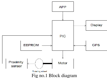
SYSTEM ARCHITECTUREThe basic modules required in system designing are GPS module, microcontroller, and accelerator pedal position sensor. In this typical general architecture the location module decides the location of the car. It is done with the help of GPS system also here actual speed of the car is also measured. Here the typical roadmap is to be stored in the gps for each area, and according to that speed of the car is decided. A GPS-based navigation system can supplement information acquired from the GPS with dead reckoning. The dead reckoning technique is used estimate upcoming location of the car according to the current speed and location of the car. The Fig no 1 shows detailed block diagram for the proposed system.
Fig no.1 Block diagram
The microcontroller selected for intelligent speed adaption should be supported for accelerator pedal position sensor and GPS assembly. The controller selected is PIC16, it is 8 bit controller also it supports 10 bit ADC, low power consumption, programmable serial USART, Master/Slave SPI serial interface, two capture compare PWM module and many more function. This kind of specifications is enough for system designing of intelligent speed adaption system. The controlling mechanism used is accelerator pedal control. It uses accelerator pedal position sensor. This pedal position sensor senses pressure applied on the pedal and it gives output voltage in range between 0-5V where 0V for pedal in rest position and 5V in the fully pressed mode. The EEPROM used to store various speed limits for each location. When GPS module detects any location then it checks the speed limit set for that location in the memory and accordingly the speed limit is set. The motor assembly is used here and a wheel is attached to the shaft. For each variation in the pedal the motor will rotate the wheel. The wheel is attached to the motor shaft in 1:1 ratio. The proximity sensor is used for counting the RPM of the wheel so that we can get the actual speed for that wheel and actually it is a feedback path given back to controller for continuously checking for the speed. The display module is used to display the detected location and RPM of the wheel also the percentage of pedal pressing.
III.PARAMETER ESTIMATION
ISA has three basic measurement parameters 1) Position
2) Information 3) Control
1)
Position
the accuracy of the position determination to within a meter. The dGPS receiver is a special FM radio receiver. A GPS-based navigation system can supplement information acquired from the GPS with dead reckoning (from compass and yaw sensor) and map-matching. The new European correction system GNSS will provide additional accuracy
2) Information
With a GPS set-up, there needs to be a digital road map which contains the speed limit for each stretch of road. The digital road map could be stored on a device such as ROM, A digital radio network, GSM, GPRS. It is necessary to check whether map is already available or not. If not then it would be necessary to build an equivalent map from scratch. We also need to decide whether the “true” location of a change in speed limit was the sign location or the location defined in the speed limit order. The map must be up to date and the opening of new roads also needs to be considered. Speed limit changes may occur in the middle of a link and this needs to be considered in an ISA map by breaking that link into sub linksat the point of change. The map should also include information for the national trunk road network, so that drivers will have ISA available on trunk roads and motorways. Once the sourcemap has been built and verified, it will be necessary to translate that map into an on-board map. The advantages of digital road map are that it is ensured that information is up-to-date also it provides a dynamic capability to change speed limits in accordance with current conditions.
3) Control
For controlling purpose there needs to be a link to vehicle throttle control and perhaps in addition to the braking system. It should be noted that the level of control over the vehicle can be “soft” in which driver inclination to speed is resisted. The “hard” in which speeding above a certain point is prevented unless an override is provided. Speed limiter is device used to limit the speed of the vehicle to the set speed by the user or location based control.
TYPES OF SPEED LIMITER
1) Direct fuel control – solenoid valve type 2) Accelerator control - cable type, apps 3) Throttle control- throttle position sensor 4) Electronic control – ECM control
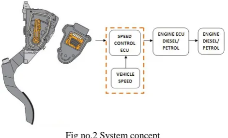
There are so many various controlling mechanism used for speed adaption but there are certain disadvantages of such systems. The fuel control system is efficient to use as it directly controls the fuel flow of the system but the disadvantage of this system it is applicable for only diesel engine and can be applied to only mechanically controlled engine. Another type used is accelerator cable type control, it can be used for both petrol and diesel type of vehicle and can be used only with mechanically linkage type vehicle but they are used in old type of vehicles only so they are not useful for retro fitment of new manufactured vehicles. The one of type used is accelerator pedal position sensor. The working principle for pedal position sensor will be cleared from Fig.2 given below
Fig no.2 System concept
engine of the car .This typical voltage we get form GPS roadmap database according to that values map matching will decide actual speed and accordingly input voltage to the engine
IV. RESULT AND DISCUSSION
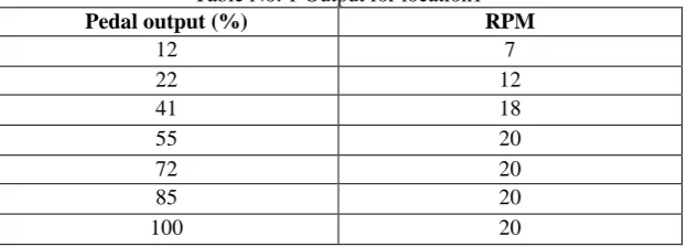
In the system discussed above our objective for demo purpose is such that once the location is located and speed limit (in rpm) assigned to that location is given to the microcontroller then even if the pedal is pressed the rpm of the motor should not increase. Here we have given speed limits for each location in RPM and proximity sensor is used for getting the exact rpm count. Here the output of the pedal is shown on the display in terms of percentage of pedal pressing. For location 1 speed limit in given as 20 rpm so it is clear that once location is detected the rpm of motor should not cross the count of 20 rpm even though accelerator pedal is fully pressed. The following table will give exact idea about how this system will limit the speed
Table No. 1 Output for location1
Pedal output (%) RPM
12 7
22 12
41 18
55 20
72 20
85 20
100 20
The data given in the table shows that speed limit is achieved for location one. Once the rpm reached at limit 20 even though pedal pressing percentage increased till maximum i.e. 100%, the rpm of the motor is unchanged. In the similar way we can assign varying speed limits for various locations.
V. CONCLUSION
This gives study on the control system for intelligent speed adaption system for automobile. The entire system consists of GPS module, accelerator pedal position sensor module and digital road map. Speed limit is variable parameter which changes in accordance with Geographical location, Type of the road and Time of the day. Speed limiting can bring safety benefits and reduction in accidents. Increase in fuel efficiency can be achieved with implementation of speed limiter. The accelerator pedal position sensor control system is suitable than both other system as it can be retrofitted to any kind of vehicle and here vehicle is electronically controlled. This system will enhance driver’s safety also it is useful while driving on unknown road.
REFERENCES
[1] Samantha Jamson, Oliver Carsten, Kathryn Chorlton and Mark Fowkes(1996) “Intelligent Speed Adaptation Literature Review and Scoping Study”. University of Leeds, MIRA Ltd, and TfL
[2] S.Sanjay pramanathan, P. M. Santhosh Kumar (2014), “Location Sensitive Speed Adaptation System for Automobiles” .IJIRSET, Volume3, Special Issue 4, April 2014
[3] Almqvist S. & Nygard M.(1997) “Dynamic speed adaption: Afield trail with automatic speed adaption in urban area Bulletin 154”. Department of traffic and planning Engineering, university of Lund ,Sweden
[4] Andresson G. and Nilsson G.(1997) “Speed management in Sweden. Swedish national road and transport research institute (VIT) Linkoping” [5] Barbosa H.M. Tight M.R &May A.D.(2000). “A model of speed profiles for traffic calmed roads.” Transportation Reasearch A,34, pp103-123 [6] Besseling H. & van Boxtel A.(2001). “Intelligent Speed Adaption: result of the dutch ISA trail- summery.” Transport Reaserch Center ministry