Wireless Power Transfer for Electric Vehicle
Applications
Amal Jose George1, Athira K S2, Gishnu Mohanan3, Renas K Nasser4, Eldhose K A5
U.G. Student, Department of Electrical and Electronics Engineering, MACE, Kothamangalam, Kerala, India1, 2, 3, 4
Assistant Professor, Department of Electrical and Electronics Engineering, MACE, Kothamangalam , Kerala, India5
ABSTRACT: Wireless power transfer (WPT) using magnetic resonance is the technology which could set human free from the annoying wires. In fact, the WPT adopts the same basictheory which has already been developed for at least 30 years with the term inductivepower transfer. WPT technology is developing rapidly in recent years. At kilowattspower level, the transfer distance increases from several millimetres to several hundredmillimetres with a grid to load efficiency above 90 percentage. The advances makethe WPT very attractive to the electric vehicle (EV) charging applications in bothstationary and dynamic charging scenarios. This project reviewed the technologies in the WPT area applicable to EV wireless charging. By introducing WPT in EVs, theobstacles of charging time, range, and cost can be easily mitigated. Battery technologyis no longer relevant in the mass market penetration of EVs. It is hoped that researcherscould be encouraged by the state-of-the-art achievements, and push forward the furtherdevelopment of WPT as well as the expansion of EV
.
KEYWORDS: Dynamic charging, electric vehicle (EV), inductive power transfer (IPT), safety guidelines, stationarycharging, wireless power transfer (WPT).
I. INTRODUCTION
Until now, the EVs are not so attractive to consumers even with many governmentincentive programs. Government subsidy and tax incentives are one key to increase themarket share of EV today. The problem for an electric vehicle is nothing else but theelectricity storage technology, which requires a battery which is the bottleneck today due to its unsatisfactory energy density, limited life time and high cost.Besides thecost issue, the long charging time of EV batteries also makes the EV not acceptable tomany drivers. For a single charge, it takes about half an hour to several hours depending on the power level of the attached charger, which is many times longer than thegasoline refuelling process. The EVs cannot get ready immediately if they have runout of battery energy. To overcome this, what the owners would most likely do is to find any possible opportunity to plug-in and charge the battery. It really brings sometrouble as people may forget to plug-in and _nd themselves out of battery energy lateron. The charging cables on the oor may bring tripping hazards. Leakage from crackedold cable, in particular in cold zones, can bring additional hazardous conditions to theowner. Also, people may have to brave the wind, rain, ice, or snow to plug in with the risk of an electric shock[1].
were just wondering whether the WPT could be realized efficiently at a reasonable cost. The research team from MITpublished a paper in Science, in which 60 W powers is transferred at a 2-m distancewith the so called strongly coupled magnetic resonance theory. The result surprisedthe academia and the WPT quickly became a hot research area. A lot of interesting works were accomplished with different kinds of innovative circuit, as well as the systemanalysis and control. The power transfer path can even be guided using the domino-form repeaters. In order to transfer power more efficiently and further, the resonantfrequency is usually selected at MHz level, and air-core coils are adopted.
II. LITERATUREREVIEW
[1]S. J. Gerssen-Gondelach and A. P. C. Faaij,"Performance of batteries forelectric vehicles on short and longer term"-Wireless power transfer has been a populartopic of recent research. Most research has been done to address the limitations of coil-to-coil efficiency. However, little has been done to address the problem associatedwith the low input power factor with which the systems operate. Wireless power transfer(WPT) is possible because of resonant circuits. When a transmitter circuit is tunedto resonate at the same frequency as a receiver circuit, power is transmitted wirelesslythrough the magnetic coupling of the inductive coils found in the circuits. Becausethe power is transferred by magnetic coils, there is little electric contact danger to anybiological entity. Electronics within the charging area are also unaffected unless they areresonant at the same frequency. Near-field WPT systems are of two types: inductive,which use magnetic field coupling between conducting coils, and capacitive, which use electric field coupling between conducting plates to transfer energy . For medium rangeapplications (in which the distance between the transmitter and the receiver couplers iscomparable to the size of the couplers, as in EV charging), inductive WPT systems havetraditionally been preferred. After market stationary chargers are already available,and some EV manufacturers have announced plans to introduce built-in stationaryinductive WPT systems as early as 2018. However, for magnetic ux guidance andshielding, inductive WPT systems require ferrite cores, making them expensive andbulky. Also, to limit losses in the ferrite, the operating frequencies of these systems arekept under 100 kHz, resulting in large coils and low power transfer densities. The highcost and low power transfer density are particularly problematic for dynamic WPT, asthese systems need to have very high power capability to deliver sufficient energy tothe vehicle during its very brief time passing over a charging coil.
[2]B. L. Cannon, J. F. Hoburg, D. D. Stancil, and S. C. Goldstein, “Magneticresonant coupling as a potential means for wireless power transfer to multiple smallreceivers"-There are four basic topologies of compensation circuits, namely series -series (SS), series - parallel (SP), parallel - series (PS) and parallel - parallel (P P)[I]. Each topology hasits inherent advantages and disadvantages, The SS topologyneeds load-independent capacitors while other topologies require variable compensatingcapacitors to operate at a given frequency. However, the load current of the SS topologyvaries with the variation of load, which is not suitable for battery charging. Othertypes of compensation circuits have been introduced to overcome limitations of thesebasic topologies. A systematic comparison between the SP and LCL-LC topologieswas done in, which showed that the LCL-LC topology had outstanding propertiescompared to the basic SP topology thanks to its stable load current, low source currentand simple control.
recent improvements in power electronic technologiesthis is about to change. Designing closely coupled systems is a well-known procedure.Designing loosely coupled IPT systems, however, can be a daunting task. Many designexamples have been described in the literature, but no generalised design procedureexplaining how to go about designing a complete system has been found. In thispaper a design methodology is proposed to deal with the additional complexities ofloosely coupled systems.
[4]A. P. Sample, D. A. Meyer, and J. R. Smith, "Analysis, experimentalresults, and range adaptation of magnetically coupled resonators for wireless powertransfer"-Concept of wireless power transfer has been discovered widely since Nikola Tesla carried out his first experiment about pursuing his idea on wireless lighting andelectrical distribution after successfully invent an alternating current. Thereafter agreat interest and investigation on that area began. According to working principles,wireless power transfer technology can classified into few method of principle such asmicrowave, laser, photoelectric, radio waves (RF), magnetic resonance and inductivecoupling method. Based on the power transfer distance wireless energy transfer methods can be categorized into two types; near field and far field. Laser, photoelectric, RFand microwave can be considered as far field energy transfer methods while inductivecoupling and magnetic resonance coupling are based as near field approaches. This typical inductive power transfer (IPTS) schemes are limited to a few centimetres. Currenttechnology of electrical vehicles charging allows EV battery charges by plug-in cablesource into receptacle on the vehicle. However, this conventional method will exposedEV owner to physical and safety hazard such as electrocution due to poor aestheticsystem and inconvenient charging situation. Therefore a convenient, affordable andsafety station to charge EV are required. Wireless power transfer for electric vehiclecharging system would be a convenient feature of solution for this matter. The processis fully automated, whereby no human handling works are required to perform thecharging process.There are two concept enabled in EV charging system; stationary anddynamic. Stationary WPT can replace the charging cable for PEVs whereby activatedwhen vehicle reaches to the charging area. While the concept of dynamic WPT chargedwhile vehicle is moving in a road. This particular concept will increase the effectivedriving range while reducing the volume of battery storage however required large areaand costly.
III.WIRELESSPOWERTRANSFER
Wireless charging consists in transferring energy from the source to the load without physical contact. This technology can be applied to EV battery charging for whichdaily recharge is mandatory. The tedious and inconvenient aspects of connecting thepower cable hinder some users and may hinder the development of the EVs. A user friendly solution consists in using a system of power transmission without contact. Thissolution provides ease of use and a good robustness to vandalism [3]. A general blockdiagram for the contactless charger for EV battery is shown in Fig. (a)
It includes several stages to charge an EV wirelessly. First, the utility ac power is converted to a dc power source by an ac to dc converter with power factor correction.Then, the dc power is converted to a high-frequency ac to drive the transmittingcoil through a compensation network. Considering the insulation failure of the primaryside coil, a high-frequency isolated transformer may be inserted between the dc-ac inverter and primary side coil for extra safety and protection. The high-frequency currentin the transmitting coil generates an alternating magnetic field, which induces an acvoltage on the receiving coil. By resonating with the secondary compensation network, the transferred power and efficiency are significantly improved. At last, the ac power is rectified to charge the battery
Power electronic device and power control
In a WPT system, the function of the primary side power electronics converter isto generate a high-frequency current in the sending coil. To increase the switching frequency and efficiency, usually a resonant topology is adopted. At the secondaryside, a rectifier is adopted to convert the high-frequency ac current to dc current.Depending on whether a secondary side control is needed, an additional convertermay be employed. The primary side converter may be a voltage or a current sourceconverter. As a bulky inductor is needed for the current source converter, the mostcommon choice at the primary side is a full bridge voltage source resonant converter.A typical wireless power circuit schematic is shown in the figure (b).
(b)
IV.EXPERIMENTALRESULTS
The transmitter section of WPT model. It consist of mosfet which acts as the inverter,compensation network and various IC to drive the MOSFET.The transmitting coil is connected to the transmitter section.
Transmitter Receiver
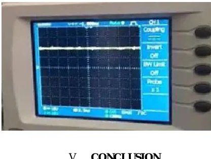
Output waveform in CRO
Figure shows the output voltage waveform obtained in the CRO.It is clear that a ripple free output waveform is obtained.
V. CONCLUSION
charging system and its misalignment tolerance and efficiencyIt is clear that electric vehicles are unavoidable because of environment and energyrelated issues. Wireless charging will provide many benefits as compared with wiredcharging. In particular, when the roads are electrified with wireless charging capability,it will provide the foundation for mass market penetration for EV regardless of batterytechnology. With technology development, wireless charging of EV can be brought tofruition. In future efficiency can be further increased by introducing suitable core between the transmitter and receiver so that maximum flux link with receiver.Problemsdue to varying distance between coils can be mitigated if a movable core can be introduced. Further studies in topology, control, inverter design, and human safety are stillneeded in the near term.
REFERENCES
[1] S. J. Gerssen-Gondelach and A. P. C. Faaij,"Performance of batteries for electric vehicles on short and longer term",J. Power Sour., vol. 212, pp.111129, Aug. 2012.
[2] B. L. Cannon, J. F. Hoburg, D. D. Stancil, and S. C. Goldstein,Magnetic resonant coupling as a potential means for wireless power transfer to multiple small receiversIEEE Trans. Power Electron., ,vol. 24, no. 7, pp. 18191825, Jul. 2009.
[3] O.H. Stielau, G.A. Covic,"Design of loosely coupled inductive power transfer sys-tems",IEEE Trans. Power Electron., vol. 4, no. 9, pp. 32433262, 2000.
[4] A. P. Sample, D. A. Meyer, and J. R. Smith, Analysis, experimental results,and range adaptation of magnetically coupled resonators for wireless power transfer",IEEE Trans. Ind. Electron., vol. 58, no. 2, pp. 544554, Feb. 2011