INTERFACIAL FRACTURE IN STEEL-CONCRETE (SC) ELEMENTS
(AN ANALYTICAL STUDY)
Dhrubajyoti Datta1, Amit H. Varma2, Vikas Tomar3
1 PhD Candidate, Lyles School of Civil Engineering, Purdue University, West Lafayette, IN-47906, USA
2 Professor, Lyles School of Civil Engineering, Purdue University, West Lafayette, IN-47906, USA 3 Professor, Department of Aeronautics and Astronautics, Purdue University, West Lafayette, IN-47906,
USA
Abstract
SC walls are of great importance to the nuclear energy industry. It consists of a concrete wall connected to steel plates using shear connectors and tie rods at regular intervals. The steel plates serve as the formwork for concrete casting. Prior research focused on the assessment of local and global failure modes for SC walls. The crack origination, propagation and branching at the interface level is yet to be evaluated. This paper aims to identify the possible interfaces of the SC wall module and establish elasto-plastic fracture mechanics (EPFM) techniques with inclusion of certain non-linear parameters to shed light on certain major fracture parameters that govern the failure of its components.
The failure of an SC wall could be governed by the slipping of shear connector elements, though tensile yielding of steel or compressive crushing of concrete are probable failure modes as well. A path-independent energy conservative method is used to assess the fracture toughness parameters for the slip and pullout failure modes of shear connector elements. The inter-dependence of the individual fracture toughness parameters, i.e. the crack tip opening displacement (CTOD) and strain energy release rate (SERR) is also established. The plasticity effects at the crack tip are expressed through a boundary value problem formulation utilizing yield stresses at the crack tip. Tension hardening/softening effects at the crack front are addressed through crack tip correction terms. The computational verification of the analytical model proposed in the paper is currently in process.
FORMULATION OF FRACTURE MECHANICS BASED ANALYTICAL MODEL
Analytical formulation
The J-integral can be used to determine stress intensity in a field when the exact configuration in the vicinity of crack tip is unknown. The integrals are formulated based on a continuously differentiable stress fields. The J-Integral is identical to energy release rate for a planar crack extension and it acts as an intensity factor for singular stress and strain fields at the crack tip. In the proposed model, the quasi static crack propagation is assumed to be time independent and is limited to elasto-plastic materials with stress free crack edges. The J-integral is modified to incorporate the strain-hardening post peak plastic response of the steel-concrete interface using an elasto-plastic fracture model. Although it’s well known that steel doesn’t exhibit a complete elasto-plastic behavior, in the proximity of micro cracks, the geometric non-linearities can be ignored.
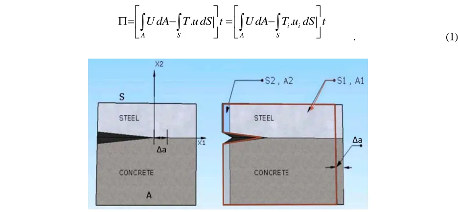
An interfacially cracked steel-concrete composite section was considered with thickness t, area A and boundary S, and volume V which is controlled for the entire domain. As the volumeV experiences surface traction T along the boundary S (experimentally simulated by step loading), the potential energy is given in terms of the strain energy density (U) and displacement vector (u) as
. i. i
A S A S
U dA T u dS t U dA T u dS t
. (1)Fig 1. Correlation between displacement of controlled volume and crack tip propagation
If the crack is extended by Δa, potential energy of the control volume should also change. Considering
1 and
2 to be the PE of the controlled volume before and after crack extension, the potential energy releaserate is given by
2 1 0
lim .
a
A t a
Assuming the module to be part of an infinitely large structure, the potential energies
1 and
2 can be computed by keeping the crack length fixed and moving the controlled model by the same amount towards the left as the crack propagates towards the right i.e. Δa. The section highlighted in black outline represents propagation of controlled volume towards left due to crack extension, while the region highlighted in red represents its initial state.Referring Fig 1, Eq(2) can be expressed as
2 2 1 1
0
1
lim
i i i ia
A S A S
d
U dA
T u dS
U dA
T u dS
t
dA
t a
. (3)The potential energy released by the system due to extension of the crack front is a result of the exchange of stresses and tractions at the interface. Hence, in the succeeding equations, the strain energy densities and traction slip parameters have been disintegrated into components to enforce contribution of both materials towards crack propagation, which is expressed as
2 2 2 2
1 1 1 1
2 2 2 2
, , , ,
0
1 1 1 1
, , , ,
1
lim C i C i C S i S i S
a
A S A S
C i C i C S i S i S
A S A S
d
U dA T u dS U dA T u dS dA t a
U dA T u dS U dA T u dS t
, (4.1)
1 2 2 1
2 2 2 2 1 1 1 1
, , , , , , , ,
0
1 2
1
lim
(
C S)
(
i C i C i S i S)
(
i C i C i S i S)
a
A A S S
SERR SERR
d
U
U dA
T
u
T
u
dS
T
u
T
u
dS
dA
a
(4.2)where, Uc, Ti,c are the strain energy and traction component corresponding to concrete and Us, Ti,s
corresponds to steel. The superscripts 1 and 2 correspond to the domain configuration before and after crack growth. As shown in Eq. 4.2, the differential change in potential energy of the control volume can be correlated to the SERR-1 (strain energy release rate due to preferential interfacial crack) and SERR-2 (Strain energy release due to traction slip).
For the limiting case (Δa 0); we can assume the displacement field to vary linearly between S1 and S2. For
small regions u can always be assumed to be varying linearly even for non-linear displacement fields as long as there is no discontinuity. Furthermore; the traction, stress and strain fields should also be constant
for linear displacement fields. Hence, we can safely state that,
T
i C, 1
T
i C, 2
T
i C,and
T
i S,1
T
i S, 2
T
,i S. Also, since the displacement field for both steel and concrete are same at the boundaries S1 and S2, we
1 2 1
1 2
2 1 2 1
, , , , , ,
0
1 2 , ,
0
1
lim
(
)
(
)
(
)
1
lim
(
)
(
)(
)
C S i C i C i C i S i S i S
a
A A S S
C S i C i S i i
a
A A S
d
U
U dA
T
u
u
dS
T
u
u
dS
dA
a
U
U dA
T
T
u
u
dS
a
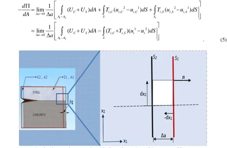
. (5)
Fig 2. Elemental area enclosed by boundaries S1 and S2 separated by Δa
From Eq (5), we observe that elemental area dA=Δa.dx2. Upon enforcing the displacement field correlation,
we obtain
1 2
2 0
2 2
1
lim .
( ) .
T i
i a
i
A A S
T i T i
i i
i i
S S S
u d
U a dx T a dS
dA a x
u u
U dx T dS U dx T dS
x x
(6)
At the interface S1=S2=S and since the total strain energy is equivalent to the external work done the J-integral is given by
2
i i
i
S S
u
J
W dx
T
dS
x
; (7)which can be expressed as
such a scenario i.e. (J ≠ SERR). But, J can still be calculated for the problem geometry and equated to the crack tip opening displacement (CTOD).
Extending Eq 8 to incorporate plasticity effects, we obtain
2 2
steel conc
i i
conc i steel i
i i
S S
u u
J U dx T dS U dx T dS
x x
. (9) The subsequent equations facilitate an arbitrary shift of the crack front yielding the energy release rate towards the plastic zone.
Fig 3.(a)Contour surrounding the plastic zone: Dugdale model (b)Stresses and traction fields surrounding plastic zone
From Fig 6. the boundary interface path for the integral path can be specified as;
1 2 1 2
:
;
0
:
;
0
conc
Y steel
Y
on lower path S
T
ds
dx dx
S
on upper path S
T
ds
dx dx
where, σY represents the yield stress at crack tip. Hence Eq (10) can be expressed as,
1 1
1 1
0 0
1 1 1
1 1 1
0 0 0
0
0 0
( )
[ ] [CTOD 0]
b conc b steel
conc i steel i
conc i steel i
b b b
conc steel conc steel
conc steel Y
b Y conc steel Y
u u
J U T dx U T dx
x x
u u u u
T dx T dx dx
x x x
u u
(10)Therefore the J-Integral can be related to the elasto-plastic crack tip opening displacement as
Modified J-integral to compensate for tension softening at crack tip
It is important to note that unlike the elasto-plastic nature of the steel-concrete interfacial crack tip propagation; the stud would exhibit a post-peak softening behavior which would require bridging of Rice’s model to some additional crack tip parameters. There is no well-defined crack tip opening when the slip or tearing of the shear connector occurs, due to the fact that the localized energy around the fracture process zone would cause crushing of the surrounding concrete. The fracture energy is smeared across the interface to delocalize the shearing or slip across the surrounding concrete microstructure.
If the unloading of a specimen follows the identical stress-strain path as its loading phase, such non-linear elastic behavior can be justified by the path independence of the J-Integral. But, in case of failure of shear connectors, the material develops tension softening leading to growth of fracture process zone (FPZ) by interlinking crack flanks. The confusion in applying the J-integral to such interfaces arises during evaluation of the contour surrounding the process zone, when the unloading of the material defies the non-linear elastic assumption behind the basic J-Integral formulation. The issue is addressed by considering a contour Γremote
far from the FPZ that passes through the concrete microstructure and the steel plate. Due to path independence of the J-integral the contour Γpz wrapped around the fracture process zone possesses the same
value as Γremote. When the material enclosed by the process zone unloads elastically with decreasing tensile
traction σ and increasing crack opening (on the line y=0) δ; the material at the process zone (
:
0
0
pz
y
) must also unload in order to maintain equilibrium, which is elastic in nature and followsthe traditional stress-strain relationship. The remote contour in conjunction with the contour wrapped around the process zone allows us to determine the correlation between energy released and supplied during tension softening. In our case, a bridging model seems feasible that would result in a correction term, in addition to the integral; when the additional contour wrapped around the crack tip shrinks, which can be expressed as
2 2
0
(1
)
( )
ttip
K
J
d
E
where, σ (δ): describes the tension softening of the process zone; Ktip: fracture toughness; E: Elastic modulus;
ν: Poisson’s ratio; δt: opening at end of the fracture process zone. Critical value of the integral (
J
J
crit)occurs when the traction free crack opening
t
crit corresponding to
crit 0 . Energy consumed in the process zone is generally much greater than at the advancing crack tip. The empirical expression for σ(δ)for concrete under uniaxial tension can be stated as
0
1
u m
P
; where σm, δp , δ0 are empirically
FRACTURE OF SHEAR CONNECTOR-STEEL PLATE-CONCRETE INTERFACE WHEN SUBJECTED TO SLIP
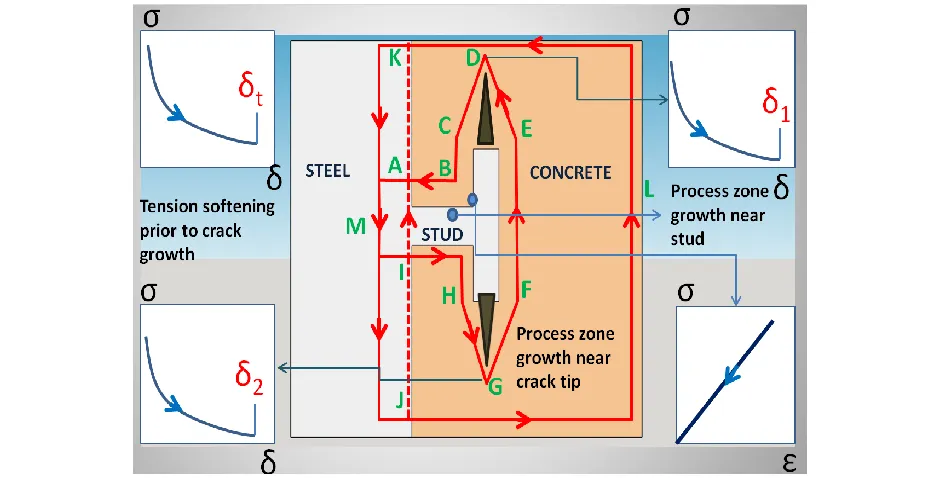
The article discusses the failure of the steel plate-concrete interface assuming an adhesive bond between the two rough interfaces. The analytical model is used to assess the fracture energy of a propagating crack front across the stud-microstructure interface. The path independence property of the J-integral is used to avoid crack tip singularities by calculating stresses and tractions along the remote contour, when the stud is exposed to slip forces. The tension softening of the process zone is taken care of by incorporating additional crack tip correction factors. The schematic diagram shows the integral paths chosen for the predicted crack front and the stress-strain behavior at some critical points in the fracture process zone.
Fig 4. Integral paths defined at the process zone to capture inelastic tension softening effects at stud-concrete-steel plate interface
The possible integral paths defined for cracks propagating parallel to the interface can be expressed as (i) Γ= LABCDEFGHIJKL: defining the entire domain (ii) Γconc = IJLKA = Γremote: defining the far field integral
path in concrete microstructure (iii) Γsteel = IAKMJ: defining the integral path in steel and (iv) Γpz
=IHGFEDCBA: integral path in fracture process zone where the crack originates and branches out. One can correlate the integral paths and incorporate the different phases of fracture propagation using the expression
.
Now, from the definition of J-integral, where δ1 and δ2 are smeared crack tip opening parallel to the interface,
one can obtain
, (12)
remote/conc steel stud
conc/remote
;
conc conc
conc
conc conc
conc
u
J
W
dy
T
dS S
S
x
, (13)
, (14)
. (15)
Dissociating the integral for crack fronts CDE and HGF, one obtains
. (16)
The expression for process zone satisfies the stress and displacement continuity. The singularity in the process zone due to tension softening is taken care of by the additional crack tip term. However, it is important to observe that we are neglecting plasticity effects at the crack tip assuming that the size of plastic zone is negligible compared to the softening phase.
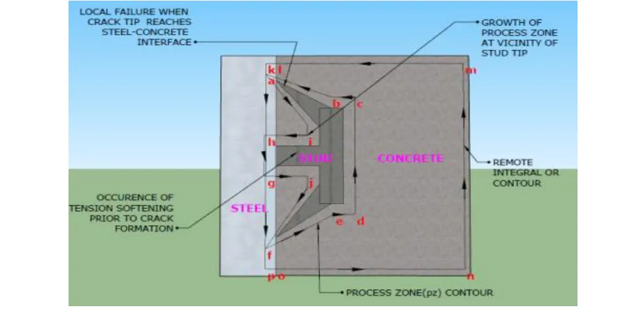
FAILURE OF SHEAR CONNECTOR-STEEL PLATE-CONCRETE INTERFACE WHEN SUBJECTED TO PULLOUT FORCES
When subjected to pullout forces the stud experiences local buckling at the connector-steel plate-concrete interface and the crack is expected to follow a path propagating at an angle from the crack tip causing local (micro-meso) failure and crushing of concrete at the base of stud. The nature of failure is opposed to the scenario when the steel plate is subjected to slip; where the cracks from stud tip branch out and coalesce resulting in a global (macro-meso) failure and debonding of the concrete. The probable integral paths for cracks propagating at an angle of θ from the crack tip can be defined as
(i)Γ= ahgfponmk , (ii)
Γ
conc=onml = Γ
remote, (iii)Γ
steel=hgfpolka
, and (iv)Γ =gjfedcbaih
pz .The failure resistance is the resultant of tensile stresses being equal to maximum concrete tensile strength directed perpendicular to the conical plug surface resulting from pullout forces at an angle of 25 degrees (for shallow embedments ) to 45 degrees (for deep embedments) and parallel to the direction of applied load [34] . The stresses are not directed towards the major axes. Hence we need to take components of the principal stresses at the fracture process zone along the predicted crack path propagation. From path independence of J-Integral one can assert Jabcdef Jklmnop andJaihgjf Jkpol.
steel
;
steel steel
steel steel steel
steel
u
J
W
dy
T
dS S
S
x
2 2
stud
(1
)
sttud stud
stud
tip
stud stud
u
K
J
W
dy
T
dS
x
E
2 2
Slip traction 0
(1
)
( )
;
T
stud
stud
tip stud
stud
K
u
d
T
dS
S
S
x
E
2 2 2 2
1 2
(1 ) (1 )
( ) ( )
CDE HGF stud
stud
tip tip
stud CDE HGF
stud
K K
u
J d d T dS
x E E
Fig 5. Integral path for the stud-concrete-steel plate interface when subjected to pullout forces
The failure resistance is the resultant of tensile stresses being equal to maximum concrete tensile strength directed perpendicular to the conical plug surface resulting from pullout forces at an angle of 25 degrees (for shallow embedments ) to 45 degrees (for deep embedments) and parallel to the direction of applied load . The stresses are not directed towards the major axes. Hence we need to take components of the principal stresses at the fracture process zone along the predicted crack path propagation. From path independence of J-Integral one can assert Jabcdef Jklmnop andJaihgjf Jkpol.
. (17)
. (18)
. (19) Bridging the integral with crack tip correction term, one obtains;
. (20)
Using the path dependence relations,
conc/remote
;
conc onml
conc
conc conc
conc
u
J
W
dy
T
dS S
S
x
steel
;
steel ahgfpolk
steel
steel steel
steel
u
J
W
dy
T
dS S
S
x
2 2
stud
(1
)
stud stud
stud
tip
stud stud
u
K
J
W
dy
T
dS
x
E
2 2
Slip traction 0
(1
)
( )
;
T
a i h g j f e d c b
stud
tip stud
stud stud
K
u
J
d
T
dS
S
S
x
E
(24)
where δ1 and δ2 are smeared crack displacements and θ is angle of the crack to the horizontal plane. CONCLUSION
The article discusses an analytical model which can be used to assess the most probable microstructural failure modes of some critical steel-concrete interfaces in composite SC wall module. It can be applied extensively in critical sections of a large SC wall system which are expected to experience high stress concentrations. From the numerical analysis of the controlled volume domain, The J-integral was found to be the difference between the gross strain energy release rate (SERR) and the tangential traction slip energy for bimaterial interface. In the case of small plastic deformations, J is expressed as the product of the crack tip opening displacement (CTOD) and the yield stress at the crack tip (σy). The deviation of cracks from the
interface depends on the crack path associated with the minimum strain energy released or lowest J-value. When appropriate contour integral paths are defined for stud-concrete microstructure-steel plates interface, the J-integral can be computed in terms of the smeared crack displacements using appropriate tension softening parameters for the crack tip. The analytical model can be easily implemented in commercial finite element softwares like ABAQUS by specifying appropriate contour paths. With recent developments in co-simulation techniques, the model can be used in devising fracture plans that can simultaneously simulate micro and macro-scale failures.
References:
[1] Rice, J. (1968). A Path Independent Integral and the Approximate Analysis of Strain Concentration by Notches and Cracks. Journal of Applied Mechanics, 35(2), 379.
[2] Varma, A.H., Malushte, S., Sener, K., and Lai, Z., (2014). Steel-Plate Composite (SC) Walls for Safety Related Nuclear Facilities: Design for In-Plane Force and Out-of-Plane Moments. Nuclear Engineering and Design, Vol. 269, pp. 240-249, Elsevier Science.
[3] Evans, A.G., Rühle, M., Dalgleish, B.J., Charalambides, P.G. (1990). The fracture energy of bimaterial interfaces. Materials Science and Engineering: A, Volume 126, Issues 1–2, 15 June 1990, Pages 53-64.
[4] Dugdale, D. (1960). Yielding of steel sheets containing slits. Journal of the Mechanics and Physics of Solids, 8(2), 100-104
[5] Li, V.C. (1997). Applicability of J-integral to tension-softening materials. Journal of Engineering Mechanics, 123(5), 531.
1 2
normal traction component shearing traction component
2 2 2
( )
( )
cos
sin
(1
)
a i h g j f c d e f p o n m l k stud stud
stud stud
stud stud
stud pz pz
tip j f e tip i ab
u
u
J
d
d
T
dS
T
dS
x
x
K
K
E
2