INTERPRETATION OF ASME CODE RULES FOR ASSESSMENT OF
GRAPHITE COMPONENTS
D. Kanse, I. A. Khan, V. Bhasin, and R. K. Singh
Reactor Safety Division, Bhabha Atomic Research Centre, Trombay, Mumbai, India-400 085 E-mail of corresponding author: [email protected]
ABSTRACT
High density and high purity grade of graphite is proposed to be used as a structural material and reflector in Compact High Temperature Reactor (CHTR), that is being designed by BARC, India. Due to statistical nature of several microstructural features, graphite shows a wide scatter in its strength properties. As a result, the design rules for graphite components are expected to be different from the deterministic design criteria typically adopted for metals. ASME Section-III, Div-V (subsection HH) provides the rules for design, construction, fabrication and assembly of graphite core components. These rules are based on probabilistic structural mechanics.
In this work, a notched tensile specimen and a fuel tube of graphite were analyzed using the ASME code procedure. The design allowables were arrived at using the in-house tensile test data of graphite. Both simplified as well as detailed (full) assessments were carried out to obtain the design margins. It was observed that the existing detailed assessment procedure that is based on three-parameter Weibull model, leads to some anomalies for the cases analysed in this work. It is not very clear to the authors whether the adjustment of threshold parameter alone is required (purely from peak stress consideration) or the Weibull modulus and characteristic strength also need to be adjusted so that the tensile strength distribution as obtained from the set of modified Weibull parameters fits the tensile test data. Our studies revealed that the former case leads to some ambiguities where the three-parameter model is leading to more conservative assessment compared to the two-parameter approach. This clearly seems to be in contradiction to the spirit of the code rules. When the latter case was adopted this apparent anomaly was resolved.
1. INTRODUCTION
Isotropic and near-isotropic nuclear grade graphites are the potential candidate materials for the moderator and major structural components of Gen IV Very High Temperature Reactors (VHTR) such as the Next Generation Nuclear Plant (NGNP) and the Pebble Bed Modular Reactor (PBMR). BARC, India is in process of designing a Compact High Temperature Reactor (CHTR) having a coolant outlet
temperature of around 1000˚C. Its internal parts such as fuel tube, reflector blocks, down comer and upper plenum block are proposed to be constructed from high density and high purity grade of graphite (Dulera et al. (2008)).
graphite specimens under uni-axial loads to quantify the scatter band in failure stress. Weibull parameters are estimated from the tensile failure stress data which are then used for generation of material reliability curve. Subsequently, design allowable strength values obtained from the material reliability curve are used for structural integrity assessment of graphite components.
2. ESTIMATION OF WEIBULL PARAMETERS AND GENERATION OF MATERIAL RELIABILITY CURVE
ASME Section III Div. 5 Subsection HH provides code rules for ‘simplified’ as well as ‘full assessment’
of graphite core components. The design rules are not for pressure retaining components and they are also not intended to ensure sealing against leakage of coolant. These design rules are based on ‘modified volume normalized Weibull theory’ (Hindley et al. (2012)) and they require Weibull parameters to be determined from the experimentally observed tensile failure stress data. Simplified rules based on two parameter Weibull distribution involve generation of material reliability curve and subsequent comparison of membrane and peak equivalent stresses with the allowable design values arrived at from the material reliability curve. The code rules for ‘simplified approach’ are more conservative and if a component can not be qualified using this approach, full assessment can be carried out. Weibull parameters based on three-parameter distribution are used for the ‘full assessment’ of graphite
components.
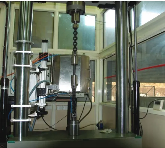
A computational code was developed to estimate Weibull parameters viz. Weibull modulus, threshold stress, and characteristic strength from the uniaxial tensile failure stress data generated in-house. About 150 graphite specimens were tested under compressive, tensile and flexural loads as per relevant ASTM standards. Figure 2.1 shows the flexible chain mechanism for tensile tests as per ASTM C-749.
Figure 2.1. Tensile test set up.
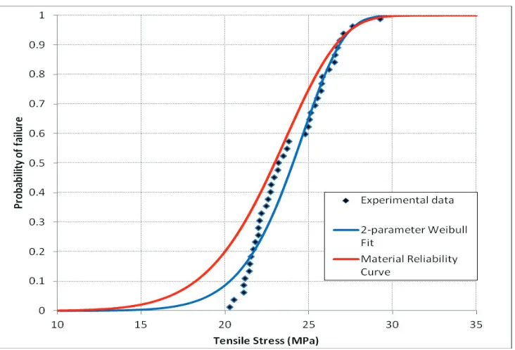
The Weibull parameters for both two-parameter as well as three-parameter distributions were estimated considering maximum likelihood method (ASTM C-1239). This approach yields smaller confidence intervals on the parameters in comparison to regression methods like Least Squares. Figure 2.2 shows the
well as three parameter distribution fits to the experimental data. Numerical values of Weibull parameters, for both types of distributions, are listed in Table 2.1.
Figure 2.2. Experimentally observed tensile failure stress distribution and Weibull’s fit.
Table 2.1: Weibull parameters estimated from tensile test data.
Type of Weibull Distribution
Weibull Modulus (m)
Threshold Stress, S0 (MPa)
Characteristic Strength, Sc (MPa)
2- parameter 11.024 0 24.857
3- parameter 1.697 20.068 24.259
The estimated Weibull parameters are, however, statistically biased, that is, they are dependent on the sample size and they approach true material parameters as sample size increases to a large number. Moreover, there will be a variation from sample to sample. As a result, the parameters are generally assumed to be normally or log-normally distributed. ASME code recommends the use of lower limit of one sided confidence interval at 95% confidence level. For calculating the desired bounds, Fisher matrix was evaluated and subsequently, a matrix of variances and co-variances of the parameters was generated by taking inverse of Fisher matrix (Wittman D.). Using the variance values from the matrix, one sided bounds on the respective parameters were evaluated. Table 2.2 shows the lower limits of one sided confidence bounds at 95% confidence level for Weibull modulus and characteristic strength. The confidence bound on threshold stress was not evaluated as this parameter is dependent on the peak stress in the component being analyzed.
Table 2.2: Lower limits of one-sided confidence bounds on Weibull parameters at 95% confidence level.
Weibull Distribution Weibull Modulus (m95%)
Characteristic Strength, Sc95% (MPa)
2- parameter 8.166 24.0052
Weibull parameters based on 2-parameter distribution were used for generating material reliability curve
required for ‘simplified assessment’ of graphite components. Material reliability curve is simply a plot of
cumulative probability of failure for 95% confidence level versus tensile stress, as shown in Figure 2.3. The allowable stress limits for a given reliability target, are derived from the material reliability curve. The reliability target depends on the Structural Reliability Class (SRC) of graphite component and the service level.
Figure 2.3. Material reliability curve for graphite.
3. FE ANALYSIS OF NOTCHED TENSILE SPECIMEN AND FUEL TUBE OF GRAPHITE
In this work, a notched tensile specimen, and a graphite fuel tube that is proposed to be used in CHTR was analysed using the ASME code rules. The objective was to understand and interpret the probabilistic based design rules recently proposed for graphite components. Detailed 3-D finite element analyses were carried out to obtain the stress distribution and subsequently the design margins were evaluated using both the 'simplified' and the 'full assessment' procedure suggested by ASME code.
3.1 FE Analysis of Notched Tensile Specimen
Figure 3.1. FE model of notched tensile specimen.
A tensile load of 300 N at one end and other suitable boundary conditions were applied to the model and a linear static analysis was carried out. Figure 3.2 shows the 1st principal stress distribution in notched tensile specimen of graphite.
Figure 3.2. 1st principal stress distribution in notched tensile specimen of graphite.
3.2 FE Analysis of Fuel Tube of Graphite
As a second exercise, an annular fuel tube of graphite proposed to be used in CHTR, as shown in Figure 3.3, was analyzed. In this proposed configuration, fuel tube carries fuel inside 12 equi-spaced longitudinal
bores (φ10 mm) made in its wall. The fuel elements would be located inside each of the bores only within 700 mm region, as shown in Figure 3.3. The liquid metal coolant flows through the central hole (φ
Figure 3.3. Geometry of fuel tube.
Since graphite core components are not pressure-retaining, the only loads which are of significance are the dead weight and the thermal loads. Figure 3.4(a) shows the 3-D quarter-model of fuel tube. The model was meshed using 10 noded tetrahedral elements as shown in Figure 3.4(b).
Figure 3.4. 3-D (a) solid and (b) meshed quarter-model of the fuel tube of graphite.
A steady-state coupled thermal-structural analysis of the fuel tube was carried out for design mechanical and thermal loads. Figure 3.5 shows the nodal temperature and the 1st principal stress distribution in the fuel tube.
50 700 (Heating Length)
(a) (b)
Figure 3.5. Nodal (a) temperature (b) 1st principal stress distribution in the fuel tube.
4. ASME CODE QUALIFICATION OF NOTCHED TENSILE SPECIMEN AND FUEL TUBE OF GRAPHITE
The structural assessment of notched tensile specimen, and graphite fuel tube was carried out as per ASME code rules. Both the 'simplified' as well as 'full assessment' procedures were employed to obtain the design margins, assuming that both the components belong to Structural Reliability Class-1 (SRC-1). For SRC-1, ASME suggests a target probability of failure as ≤ 10-4.
4.1 Structural assessment as per ‘Simplified procedure’
In this approach, the combined membrane (Cm), and membrane plus bending plus peak (Cm+Cb+F)
equivalent stresses in the component being assessed are compared with the allowable stress limits. From the material reliability curve (Figure 2.3), allowable combined equivalent membrane stress Sg(10-4) is
7.7699 MPa and allowable peak equivalent stress Rtf.Sg(10-4) is 8.601 MPa. Rtf is the ratio of mean
flexural (four point bend) to mean tensile strength. For the grade of graphite that was used in this study, the Rtf value was about 1.107
The stress distribution as obtained from detailed 3D FE analyses was used to compute the equivalent membrane and peak stresses at the ligament of notched tensile specimen. For this case, the equivalent membrane stress was 1.54 MPa and the peak equivalent stress was 5.96 MPa which are much lower than the code allowable values.
Figure 3.6. Ligament (AB) and through thickness (CD) sections in fuel tube.
4.2 Full Assessment
The ‘simplified procedure’ proposed in ASME code is conservative. As per this approach, if prescribed
limits are not met, does not imply that the graphite component is not acceptable. In such cases, ‘full assessment’ which is based on Weibull’s three parameter distribution can be carried out to check the design adequacy.
For full assessment of a component, linear elastic FE analysis of the component is carried out and equivalent stress in the sub-elements is calculated based on maximum deformation energy (MDE) theory. A sub-element is a part of an element associated with a gauss point. Subsequently, the groups of these sub-elements are formed in accordance with the criteria discussed in ASME code. Threshold stress is adjusted based on the peak equivalent stress in the component. The probability of survival (POS) of each group is determined using Weibull's three parameter distribution. Overall probability of survival is then calculated by multiplying the probability of survival of the individual groups.
As per this procedure the computed probability of failure of the component is compared with the target probability of failure applicable to that structural reliability class. A computational code incorporating the 'full assessment procedure' was developed in-house. The probability of failures of notched tensile specimen, and fuel tube of graphite, obtained from the in-house code were 4.927X10⁻³ and 3.33X10⁻² respectively. These values are much higher than the target probability of failure that is 10-4. Hence both the components do not qualify as per the full assessment procedure of ASME code.
5. RESULTS AND DISCUSSION
As per simplified assessment procedure, combined equivalent membrane and peak stresses for both notched tensile specimen as well as fuel tube of graphite were observed to be less than the design allowable values arrived at from the material reliability curve. Therefore, both the components are safe as per the simplified assessment procedure. However, full assessment of both the components, in discussion, shows that probability of failure is greater than 10-4 and hence they are unsafe. This clearly seems to be in contradiction to the philosophy of ASME code rules where the 'simplified assessment method' is expected to be more conservative than the 'full assessment method'. One important aspect that needs to be considered is that the full assessment method suggests a modification in the Threshold parameter based on the peak stress consideration. As per this approach, the threshold parameter needs adjustment if the peak equivalent stress in the component is less than the characteristic strength. Apparently, the existing
C
D
A
code rules do not suggest any modification in the Weibull modulus and characteristic strength. However, the adjustment of threshold parameter alone is not expected to give proper fit to the tensile test data. Thus, in this work, in addition to the adjustment of the threshold parameter, other two parameters, namely Weibull modulus and characteristic strength were also modified such that the modified set of Weibull parameters fit the tensile test data. Subsequently, the probability of failure for both the notched tensile specimen and the graphite fuel tube were recomputed. The calculated probabilities of failure were 8.18 X 10⁻¹³ and almost zero respectively. Hence, both the components were observed to be safe.
6. REFERENCES
ASME Boiler and Pressure Vessel Code, Sec-III, Division 5, Sub-section-HH, (2010).
ASTM C-749, "Standard test method for tensile stress-strain for carbon and graphite."
ASTM C-1239, "Standard practice for reporting uniaxial strength data and estimating Weibull distribution parameters for advanced ceramics."
Brocklehurst, J. E. and Darby, M. I. (1974). "Concerning the fracture of graphite under different test conditions," Materials Science and Engineering, 16, 91-106.
Burchell, T. D. (1996). "A microstructure based fracture model for polygranular graphite," Carbon Vol. 34, No. 3, pp. 297-316.
Dulera, I. V. and Sinha, R. K. (2008). "High temperature reactors," Journal of Nuclear Materials, 383, 183–188.
Hindley, M. P., Mitchell, M. N., Erasmus, C., McMurtry, R., Becker, T. H., Blaine, D. C., Groenwold, A. A., (2012). "A numerical stress based approach for predicting failure in NBG-18 nuclear graphite components with verification problems," Journal of Nuclear Materials.
Price, R. J. (1976). "Statistical study of the strength of near-isotropic graphite," General Atomic Project.