FLOOR RESPONSE SPECTRA OF THREE-DEMENSIONALLY
BASE-ISOLATED NUCLEAR POWER PLANT CONSIDERING
SOIL-STUCTURE INTERACTION EFFCET
LT. Ding1, F. Wang2, T. Wang3
1
Master candidate, Key Laboratory of Earthquake Engineering and Engineering Vibration, Institute of Engineering Mechanics, CEA, Yanjiao, Sanhe, Hebei, 065201, China
2
Master candidate, Key Laboratory of Earthquake Engineering and Engineering Vibration, Institute of Engineering Mechanics, CEA, Yanjiao, Sanhe, Hebei, 065201, China
3
Researcher, Key Laboratory of Earthquake Engineering and Engineering Vibration, Institute of Engineering Mechanics, CEA, Yanjiao, Sanhe, Hebei, 065201, China ([email protected])
ABSTRACT
The seismic mitigation effect of base isolation technique applied on nuclear power plants (NPP) shall be examined by considering the soil structure interaction (SSI) because current NPP seismic design codes allow foundation soil much softer than bed rocks. In this study, four multi-degree-of-freedom (MDOF) mass-spring models are built with different structure patterns: the prototype with fixed base (P), the prototype considering SSI (P_SSI), the three-dimensional isolation model with fixed base (3D), and the isolation model with SSI effect (3D_SSI). A set of time history analyses are then conducted on each model, The floor response spectra (FRS) are thus developed, which indicate that the base isolation technique effectively mitigate the seismic response, while SSI, particularly for those structures built on moderate hard soils, might amplify the structure responses.
INTRODUCTION
Fukushima Daiichi nuclear power plant accident caused by 3.11 East Japan earthquake has a great impact on Japan and even all the world. On April 12, 2011, Japanese authorities had raised the accident level to the most serious level 7, same as the Chernobyl nuclear accident. The seismic behavior of nuclear power plant had caught a lot more concerns from researchers since then. Base isolation technique has already been proved very effective to mitigate seismic responses of structures. The structure of nuclear power plant is so rigid that makes it very suitable for the base isolation technique[1]. Several studies have experimentally and numerically examined the feasibility and effectiveness of base isolation applied to nuclear power plants[2-5]. Floor response spectra (FRS) of base isolated nuclear power plant shift its dominated frequency to much lower frequency band compared with the one without isolation, thus significantly mitigating the responses of inside facilities[6]. Soil structure interaction (SSI) is another concern during the seismic design of nuclear power plant[7]. Specific issues, such as wave incoherence, passage effect, reflection and so on, have to be considered comprehensively because of the large foundation raft. However, very limited studies have been found to answer the influence of SSI on the base isolated nuclear power plants. This becomes very interesting since concerns have been raised to consider hard soil site rather than rock only. As a subsequent study of a three-dimensionally base isolated NPP technique[6], this study examines the SSI effect using four MDOF mass-spring models. Time history analyses are conducted on each model using forty ground motions. All results are presented in the form of FRS which provide insight into the seismic mitigation effect of base isolation technique.
MDOF MASS-SPRING MODELING
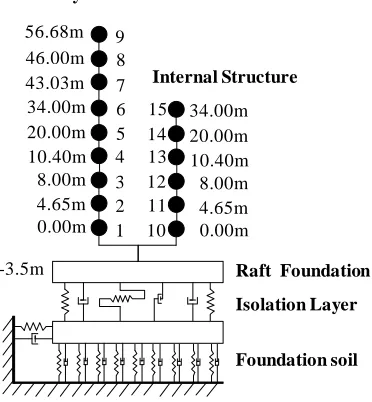
An open source code, OpenSEES, developed by University of California at Berkeley, was employed to construct the MDOF mass-spring model. As shown in Figure.1, the model consists of the safety shell, internal structure and a common raft foundation under them. The weights are respectively 18.3 million tons, 16.1 million tons and 26.7 million tons. The internal structure is 37.5m high, The NPP structure is 60.18m high and has a diameter of 38.8m. The thickness of the shell is 900mm.
The simplified model is shown in Figure.2. The safety shell and internal structures are simplified as two separate MDOF mass-spring models based on a common raft foundation. The base isolation layer is inserted under the raft. Three springs represent the isolators, two in vertical and one in horizontal. The distance between the two vertical springs is calculated according to rocking stiffness. Below the base isolation layer is the foundation soil which is represented by distributed springs and dashpots. Parameters of soil springs and dashpots are described in the following section.
Figure 1. NPP prototype structure Figure 2. MDOF mass-spring model
Soil Spring-Damper Element
(1) Vertical foundation soil spring element
Winkler soil model[8] is adopted in this study, as formulated in Eq.1:
pi = ksi (1)
where, pi denotes the intensity of pressure at one point on the soil surface; k denotes coefficient of subgrade reaction; and si is the vertical deformation at the same point on the soil surface.
Based on elastic half-space theory[9], the vertical deformation at one point si is defined as follow:
si =pib�1−υ 2�
E I (2)
From Equations (1) and (2), k is thus derived as:
k =b(1−υE 2)I (3)
Raft Foundation Safety Shell
Internal Structure
9 8 7 6 5 4 3 2 1
15 14 13 12 11 10
Safety Shell
Internal Structure
56.68m
1 2 4 3 5 6 8 7 9
10 11 12 13 14 15 46.00m
43.03m 34.00m 20.00m 10.40m 8.00m 4.65m 0.00m
-3.5m
34.00m 20.00m 10.40m 8.00m 4.65m 0.00m
Raft Foundation
Isolation Layer
where, E is the modulus of elasticity of the soil; b is the width of the foundation; υ denotes the Poisson's ratio of the soil; and I is a coefficient relate to the shape and stiffness of foundation, for rectangle rigid foundation, I = 0.88.
(2) Horizontal foundation soil spring element
Based on elastic half-space theory, Horizontal equivalent coefficient of subgrade reaction of the rectangle rigid foundation is shown as follow:
K = 4(1 +υ)Gβ√BL (4)
where, G is the shear modulus of the soil; B equals to 1/2 width of the foundation; L represents the length of the foundation; υ is the Poisson's ratio of the soil; and β is a coefficient relate to the shape and stiffness of foundation, for rectangle rigid foundation, β= 0.97.
(3) Vertical and horizontal dashpot element
Damping ratio of the soil can be obtained by soil's dynamic properties test. It is commonly small (about 5%) under the most common dynamic shear strain values. In this study, the damping ratio of soil is specified as 3%.
Classification of Foundation Soil
In this paper, three different foundation soils are studied: rock, hard soil and moderate hard soil, respectively with the shear wave speed of 1100m/s, 700m/ and 400m/s. Density of soil is 2500kg/m3, dynamic shear modulus of the soil is calculated from the following equation:
G =ρcs2 (5)
where, ρ denotes the density of soil; and cs is the shear wave speed of soil.
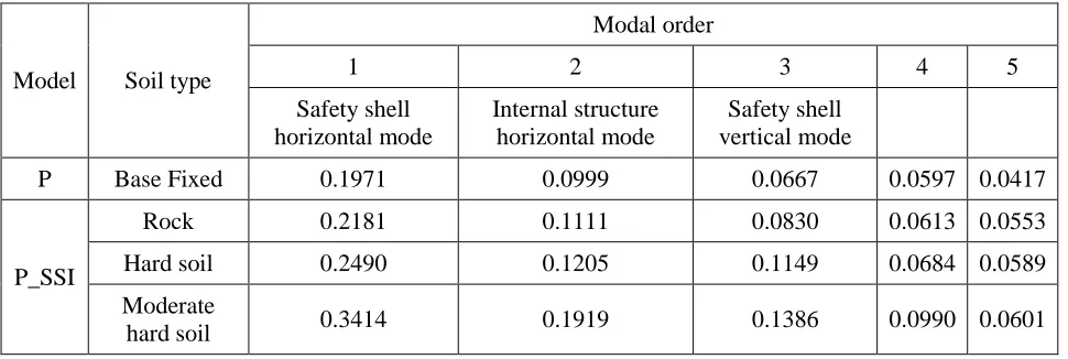
MODAL ANALYSIS
Model Soil type
Modal order
1 2 3 4 5
Safety shell horizontal mode
Internal structure horizontal mode
Safety shell vertical mode
P Base Fixed 0.1971 0.0999 0.0667 0.0597 0.0417
P_SSI
Rock 0.2181 0.1111 0.0830 0.0613 0.0553
Hard soil 0.2490 0.1205 0.1149 0.0684 0.0589
Moderate
hard soil 0.3414 0.1919 0.1386 0.0990 0.0601
Table 2: First 5 periods of models: 3D and 3D_SSI (Unit: sec)
Model Soil type
Modal order
1 2 3 4 5
Overall horizontal mode
Overall rocking mode
Overall vertical mode
3D Base Fixed 2.5151 0.2853 0.2525 0.1167 0.0604
3D_SSI
Rock 2.5189 0.2980 0.2569 0.1179 0.0604
Hard soil 2.5215 0.3217 0.2730 0.1192 0.0618
Moderate hard
soil 2.5342 0.3764 0.2956 0.1216 0.0987
FRS ANALYSIS
Figure 3. Pseudo acceleration response spectrum
Horizontal FRS Analyses
Horizontal FRS with 97.7%
exceedance probability
of the safety shell top node are shown in Figure.4-Figure.6, respectively for the rock, hard soil and moderate hard soil. Figure 7 to Figure 9 give the horizontal FRS of the top of internal structure. It is observed from these figures that:1) FRS of base isolated NPP models have larger dominant periods than non-isolated models. Acceleration responses of both safety shell and internal structure are reduced significantly. 2) Considering SSI effect, Horizontal FRS amplitude increases. SSI effect has larger influence on
the model without isolation. The softer the soil, the larger influence of SSI is observed. The peak floor acceleration is amplified almost twice for the one located at moderate hard soil site. P_SSI safety shell with rock, hard soil and moderate hard soil type, FRS amplitudes are 56.9m/s2, 77.5 m/s2 and 76.7 m/s2 respectively. Compared to P, amplitude increase by 121%, 160% and 163%. While for base isolated models, amplitude increase is very limited. Similar phenomenon is observed as well for the internal structure. And the influence of SSI is much more pronounced for the model at moderate hard foundation. The reason might be the period after shifting happens to match the dominated frequency of excitations. P_SSI amplitude increases about 3 times than P model. The SSI effect cannot be ignored for the models without isolation, while the isolated models seem not sensitive to the SSI effect.
Figure 4. Safety shell horizontal FRS (rock) Figure 5. Safety shell horizontal FRS (hard soil)
0.01 0.1 1 10
0.0 0.5 1.0 1.5
A
ccel
er
at
io
n
(
m/
s
2 )
Period (s)
0.01 0.1 1 10
0 30 60 90
A
cc
el
er
at
io
n
(
m/
s
2 )
Period (s)
3D 3D_SSI
P P_SSI
0.01 0.1 1 10
0 30 60 90
A
cc
el
er
at
io
n
(
m/
s
2 )
Period (s)
3D 3D_SSI
Figure 6. Safety shell horizontal FRS (moderate
hard soil) Figure 7. Internal structure horizontal FRS (rock)
Figure 8. Internal structure horizontal FRS (hard soil)
Figure 9. Internal structure horizontal FRS (moderate hard soil)
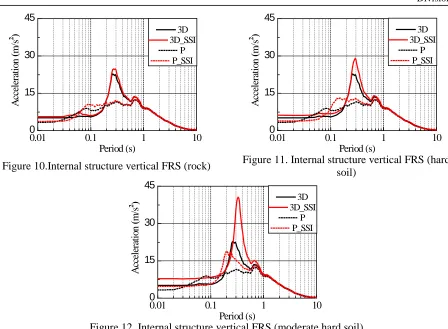
Vertical FRS Analyses
Nuclear facilities are more sensitive to vertical floor responses than horizontal ones. And this is the purpose to develop the three-dimensional isolation technique. In this study, the vertical FRS is closely examined considering different soil conditions. Shown in Figure 10 to 12 is the vertical FRS with 97.7%
exceedance probability
of the top of internal structure. It is observed that:1) FRS of base isolated NPP models have longer predominant periods than non-isolated models. Acceleration response of the internal structure is mitigated significantly.
2) In the vertical direction, FRS amplitude of base isolated NPP increases compared to non-isolated structure. However, predominant periods are elongated and move away from the vibration frequency ranging from 10 - 20Hz, deemed as the dominated frequencies of facilities and pipes.
3) Considering SSI effect, vertical FRS amplitude increases. Softer site has larger influence on structure responses than harder sites. For 3D_SSI with moderate hard soil, FRS amplitude is 40.6m/s2, while for 3D, it is 22.7m/s2, while based on the rock foundation, 3D_SSI FRS amplitude is 24.8 m/s2, almost the same as the one not considering SSI.
0.01 0.1 1 10
0 30 60 A cc el er at io n ( m/ s 2 ) Period (s) 3D 3D_SSI P P_SSI
0.01 0.1 1 10
0 30 60 A cc el er at io n ( m/ s 2 ) Period (s) 3D 3D_SSI P P_SSI
0.01 0.1 1 10
0 30 60 90 A cc el er at io n ( m/ s 2 ) Period (s) 3D 3D_SSI P P_SSI
0.01 0.1 1 10
Figure 10.Internal structure vertical FRS (rock) Figure 11. Internal structure vertical FRS (hard soil)
Figure 12. Internal structure vertical FRS (moderate hard soil)
CONCLUSION
1. Base isolation technique can effectively mitigate the horizontal response of superstructure, particularly for those located at hard soil foundation or rocks. Vertically, the mitigation effect is not pronounced because the vertical frequency is about 3Hz. However, the seismic effect is reduced within the frequency range dominating facility vibration.
2. SSI has significant influence on the structure located on moderate hard foundation. For the site with moderate hard soil, the response increases about 2 times. The influence of SSI on hard foundation, although smaller, cannot be ignored. In the vertical direction, it almost eliminates the base isolation effect. Vertical isolation on hard soil foundation shall be carefully implemented, and this is a future concern.
ACKNOWLEDGEMENT
This project was supported by National Department Public Benefit Research Foundation of China (201208013), Central Public-Interest Scientific Institution Basal Research Fund of China (2010B04), and National Natural Science Foundation of China (51008287). Any opinions, findings, and conclusion or recommendation expressed in this paper are those of the authors and do not necessarily reflect the views of the sponsors.
REFERENCES
[1] Malushte S, Whittaker A. (2005). “Survey of past base isolation applications in nuclear power plants and challenges to industry acceptance”, 18th SMiRT, K10-7, Beijing, China.
0.01 0.1 1 10
0 15 30 45
A
cc
el
er
at
io
n
(
m/
s
2 )
Period (s)
3D 3D_SSI
P P_SSI
0.01 0.1 1 10
0 15 30 45
A
cc
el
er
at
io
n
(
m/
s
2 )
Period (s)
3D 3D_SSI
P P_SSI
0.01 0.1 1 10
0 15 30 45
A
cc
el
er
at
io
n
(
m/
s
2 )
Period (s)
3D 3D_SSI
Engineering and Design, 127: 243-251.
[3] Martelli A, Forni M, Bergamo G, Bonacina G, Cesari. (1995). “Proposal for design guidelines for isolated nuclear facilities”, 13th SMiRT. Italy.
[4] Sun L, Gu FY. (1999). “A primary study of base isolation technology in NPP”, 15th SMiRT, K17-2, Korea.
[5] XIE Lili, ZHAI Changhai. (2012). “A prospective study on applicability of base isolation in nuclear power plants”, Journal of Earthquake Engineering and Engineering Vibration, CSTAM & IEM, China, 32(1):1-10.
[6] Wang F, Wang T, Ding LT. (2012). “Numerical and experimental study on seismic behavior of base-isolated nuclear power plant”, 15th WCEE, Lisbon, Portugal.
[7] Jim Xu, Sujit Samaddar. (2009). “Case Study: Effect of Soil-Structure Interaction and Ground Motion Incoherency on Nuclear Power Plant Structures”, PVP2009, Prague, Czech Republic.
[8] Zhou Jingxing, Li Guangxin, Yu Shimin, Wang Honghongjin. (2007). Foundation Engineering[M]. Tsinghua University Press, Beijing, China.
[9] Wolf J P. (1994). Foundation vibration analysis using simple physical models[M]. Englewood Cliffs(NJ); Prentice-Hall lnc.