Materials for the High Temperature Reactor (HTR)
D. Buckthorpe ~), R. Couturier 2), B. van der Schaaf
3), B.
Riou4), H.
Rantala 5), R.Moormann 6), F. Alonso7), B-C.
Friedrich s)1) NNC Ltd., Knutsford, UK
2) Commissariat/l 1' Energie Atomique (CEA.), Grenoble, France 3) Nuclear Research and Consultancy Group (NRG), Petten, Netherlands 4) Framatome ANP, Lyon, France
5) European Commission, Joint Research Centre (JRC), Institute for Advanced Materials, Petten, Netherlands 6) Forschungszentrum Juelich GmbH (FZJ.ISR), Germany
7) Empresarios Agrupados Intemacional S A (EASA.MD), Spain 8) Framatome ANP (GmbH), Erlangen, Germany
ABSTRACT
Selection and understanding of material behaviour is a vital part of the development of an advanced nuclear power plant. For the High Temperature Reactor development program within Europe this issues is being investigated for the key components of the reactor circuit through the support of the European Union Fifth Framework Programme. Material issues are being addressed for the reactor vessel and certain high temperature regions including the turbine and the graphite core. This paper reviews the main elements of the work program and provides some initial findings with regard to material choices and structural integrity needs.
INTRODUCTION
Gas-cooled reactors (GCR) and especially the HTR have been developed within Europe over many decades and considerable expertise and know-how exists within the European Community countries in this technology. A common European approach to the renewal of HTR technology through the direction of a European HTR Technology Network (HTR- TN) has been established to coordinate and encourage work-shared structures and serve as a channel for international collaboration [ 1 ].
European Community Framework Programmes have been launched to consolidate and advance the modular HTR technology in Europe [2]. These involve partnerships where principal industrial and research organisations from countries of the European Union, with the additional participation of JRC, aim to develop and consolidate European expertise and experience. Research and development actions have been set up funded within the European Union fifth framework programme to advance European HTR development in order to support industry in the design of reactors. One such Framework programme (HTR-M) deals with the selection and development of materials for the key components of the HTR. The project deals with the material for the reactor pressure vessel, high temperature resistant alloys for the internal structures and turbine and graphite for the reactor core. The project extends over a four year period and involves eight partners from four European countries. This paper gives an overall description of the HTR-M programme and its objectives and some results from initial actions focussing on the needs for feasibility assessment and assurance of structural integrity.
B A C K G R O U N D TO HTR D E V E L O P M E N T IN EUROPE
Commercial experience with gas cooled reactors began in 1956 with the generation of electricity from Calder Hall in the UK. Over the next decades this was extended to 26 Magnox Stations and 14 Advanced Gas Cooled Reactors in the UK (the last station starting service in 1989). There were also some early commercial plants in France and Spain. The coolant used for these reactors is CO2 gas.
The development of HTR Plants began in the 1950's and these used helium as the coolant to permit an increase in operating temperature. The concepts used coated ceramic fuel particles and a dispersed graphite matrix and moderator. In the years 1960 to 1990 HTR prototypes were built and tested in Europe (DRAGON (UK) - 1964 to 1975, AVR (Germany) 1966 to 1988, THTR 300 (Germany) 1983 to 1989). These provided a valuable foundation on which to base future HTR development.
Following continued interest in larger steam cycle plants in Germany, Russia and the United States through the
1970's commercialisation seemed promising in the early 1980's with the medium sized concept developed in Germany for industrial process heat applications. This was based on passive safety features and a side by side modular arrangement and set down many of the principles of today's advanced modular designs. The commercial development of this HTR-MODUL plant was however terminated in 1990 following the decision to decommission the THTR-300 demonstration plant.
\ '
i
!
SMiRT 16, Washington DC, August 2001 Paper # 1943
Renewed interest in HTR's in Europe came following the development of the HTR coupled to a gas turbine power conversion system and the recent developments of the industrial prototypes GT-MHR (in Russia) and PBMR (in South Africa) which are supported by International teams with a strong European involvement.
OVERALL OBJECTIVES AND DESCRIPTION OF THE HTR-M PROJECT
The objectives of the project are to provide materials data information for key components for the development of High Temperature Reactor technology in Europe. The major components covered include:
• Reactor vessel
• High temperature areas (internal structures and turbine) • Graphite structures including oxidation
The work programme illustrated in Fig. 1 is divided up in to three Work Packages according to the type of materials and the conditions experienced:
Work Package 1
Design information for the HTR Reactor Pressure Vessel (RPV) is not well established or formalised under HTR relevant conditions and further improvement is needed in the areas of design analysis, structural integrity analysis and materials properties data. Also information is needed on manufacturing of products and parts, design property data, the influence of environment (neutron-irradiation fluence, operational temperature, and helium environment) and behaviour of welded joints. The latter in particular is seen as an important feasibility issue. The objective therefore is to investigate and confirm the choice of candidate material options for different HTR concepts, in relation to both normal and accident conditions, and to compile their design properties.
The work involves a review of vessel materials and their properties, focusing on existing thermal gas-cooled reactors and previous high temperature reactors and a setting up of a materials property database on design properties. This will lead to a recommendation for appropriate vessel materials, depending on operating conditions, and the identification of data omissions and the selection of a material for testing under irradiated and non-irradiated conditions. The work package will consider materials for a "cold" (current PBMR) and "warm" (GT-MHR) vessel option. Specific tests on welded joints are to be performed covering tensile, creep and / or compact tension fracture specimens to determine representative properties including the effects of irradiation. A further review and synthesis is planned on completion of the irradiation test work and examination.
Work Package 2
The components of the primary circuit operate at temperature above 600°C and up to 850°C in order to achieve high energy levels and high cycle efficiency. For such components a number of metallic and ceramic materials are required in the region of the core and reactor internals (i.e. metallic, ceramic and composite materials) and for the core support and other structures. For these materials and components, some data exists but the information and experience are not well established for the HTR environment. Also highly loaded metallic materials are required for the turbine components for which the expected working conditions are beyond today's industrial experience and a significant effort of material development is required in this area.
The work involves the formation of a database of properties that takes account of the experience on existing high temperature and gas cooled reactors. The data base will include a reference to material composition, microstructure, manufacture (products and parts, etc.) and extend to materials required to withstand temperature levels experienced in emergency modes (e.g. Carbon based materials reinforced by carbon fibers, Ni-based alloys, etc.). For the turbine, the two most promising grades are studied looking at different options, manufacturing aspects and characterisation of improved alloys made by various manufacturing routes. Mechanical tests needed to quantify the materials in the HTR environment are to be performed with tensile, fatigue, short term creep and creep / fatigue tests planned (in air, vacuum, helium) at temperatures up to 1000°C. For the reactor internals the main area of testing will be for the control rod cladding and for the turbine, the discs and blades. The results of the test programme will be stored in an appropriate database and recommendations made for long term verification of the chosen materials.
Work package 3
To ensure retention of knowledge and expertise some limited investigations will be conducted to establish a graphite data base (taking benefit from existing data bases of material information, i.e. IAEA) as a preliminary stage to more detailed work involving testing and possible developments of new graphites. The work package also involves test work to investigate the influence of oxidation arising from severe air ingress with core burning and an investigation of protective coatings and innovative C- based materials. Overall this work package is expected to provide a platform of material data for future application and selection of graphites for the HTR.
MATERIAL ISSUES FOR HTR FEASIBILITY
HTR Reactor Pressure Vessel (RPV)
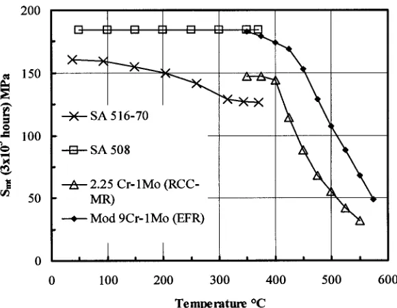
This is a key component and HTR-M investigations will establish the available information on a few selected vessel steels and a database for design and feasibility investigations. Two types of materials are currently used for RPV's, depending on whether the temperature of the pressure boundary under normal operation or design conditions exceeds the limit for LWR pressure vessels of 370°C.
Most designs of future plant make use of the either SA 508 steel for insulated vessels or modified 9Cr 1Mo steel for 'inlet temperature vessels'. These materials have similar strength levels at temperatures up to 370°C. The use of modified 9CrlMo steel allows higher temperatures with only a gradual reduction in design strength at temperatures up to 450°C. Above 450°C allowable stresses for all materials fall off rapidly. Modified 9Cr 1Mo steel has an even bigger advantage over the other materials at these higher temperatures. At 500°C for example, RCC-MR indicates that its design strength is twice that of 2¼ Cr-lMo steel (Fig. 2)
Existing LWR pressure vessels in SA 508 and its European derivatives encompass the conditions in proposed HTR vessels with respect to operating temperature, wall thickness, design features (thick flanges etc.) and irradiation levels. The large database and the extensive fabrication experience from LWR programmes provide a sound basis for HTR vessel design. The most obvious gap in data relates to possible transients involving temperatures above the usual LWR limit of about 370°C.
A substantial data base and fabrication experience exists at least for CO2 cooled reactors in the UK, with respect to C-Mn steels similar to the SA 516-70 grade specified in Chinese designs. There is European experience of complementary high temperature materials (2 ¼ Cr-lMo grades). There should be relatively few problems in assembling an adequate data- base extending to temperatures involved during transients.
The above considerations leave modified 9Cr-lMo steel with the most uncertainties as to the available data base and fabrication experience with respect to HTR vessel characteristics. This material also potentially has the wider applicability and since for the Framework Program it is only possible to test one material within the High Flux Reactor this represents the most likely candidate for the experiments. The extent of testing of control specimens is expected to cover as received (welded and post weld heat treated) and irradiated material (irradiation time about 100-.200 hours). Thermal ageing effects in 40 years at 450°C may be significant but useful experiments may not be possible within the time scale of HTR-M.
HTR High Temperature regions
For internal structures austenitic and ferritic steels can be used for some of the non graphite components (core support plates, grids) where there is an established experience with the steel in gas and other elevated temperature reactors. Figure 3 shows a materials temperature verses design code applicability indicating the materials, projects and design codes used in time independent and time dependent regimes. In general operability and applicability up to temperatures of 550°C has been firmly established for some materials within projects such as the Advanced Gas Cooled Reactor in the UK, the European Fast Reactor Project and High Temperature Reactor Projects such as AVR. Some C/C composites have also been investigated for use on HTTR for the control rod. The use of such materials is considered to provide increased thermal resistance offering potential for improved reactivity control during shutdown and for allowing the normal operating temperatures of future reactors to be increased. Experience of materials for operation at much higher temperatures at the moment rely heavily on Nickel based and Fe-Cr-Ni Alloys (Fig. 3). For the HTR which has the additional effect of a helium environment the PNP and Japanese He/He exchangers provide some important experience.
For the turbine components, especially the turbine discs and blades, criteria for material selection are to be based on a safe operation period, of say 60,000 h at 3000 r.p.m (50 Hz), with upper temperature limits in the range 850 to 950°C. Candidate alloys for the disc must have a sound industrial base and be capable of production of large defect free ingots with good forging properties and proven thermal stability. Candidate alloys for the disc include A286 (Cr Ni Fe), IN 706, IN718 and UDIMET 720. The introduction of HIP material currently being investigated for the Fusion Reactor also offers the possibility of producing near finished sized components suitable for turbine discs. For the turbine, materials for cooled and non-cooled blades have to be investigated (although the former clearly offers cost advantages) and there may be an additional requirement to cover the blades with a coating for protection against the helium gas. The effect of the helium environment will be visible in different material layers that show different kinds of micro-structural changes (corrosion). Coatings can
improve the resistance. Metallurgical factors such as cobalt content of the material also have to be assessed with regard to activation potential which may impact on maintenance costs.
Graphite components
a)
Properties
The graphite core is a key component that affects safety and operability of the reactor. As well as acting as a neutron moderator and shield, it is a structure that generally provides channels for the passage of fuel and control devices, and coolant flow. The problem is that when irradiated by fast neutrons, graphite suffers damage to the crystallite structure. The resulting damage causes a change in all the physical and mechanical properties of the graphite e.g. strength, coefficient of thermal expansion (CTE), and thermal conductivity.
Ideally, the graphite chosen for HTR designs should be reasonably isotropic, exhibit small dimensional change behaviour, and have a low CTE, a high thermal conductivity, a high irradiation creep constant, a low Young's modulus and a high strength. The problem is that many of these properties are not compatible in practice for normal commercial graphites e.g. graphites with high strength also have a high Young's Modulus. Other factors affecting the choice of graphite would be impurity levels, cost and machinability.
Most of the available irradiated materials data were obtained from various materials test reactors (MTRs). For a future design it might not be possible to generate a complete irradiated material property database for a particular graphite in advance of the design and construction phases of a reactor. In such cases, however, it might be possible to use existing databases for similar graphites, and the current understanding of irradiation damage in graphites, to 'derive' the required information. Over the past 60 years, R & D activities have been undertaken in a number of countries to investigate graphite properties. The IAEA International Irradiated Graphite Database Technical Steering Committee provides a valuable forum for the exchange of information and opinion on graphites and has recently held a seminar to review the current situation [3]. It is currently compiling a database on graphites past and present.
Many of the graphites used in previous core designs are no longer available in practical terms for a number of reasons. It could be that the coke used as the main raw material has either run out or would be very expensive to mine. It might be that the manufacturer no longer exists or that the experience has been lost, and so the production techniques and equipment no longer exist in Europe or elsewhere.
The decline in the ability to manufacture nuclear grade graphite in large quantities in the UK is an example of the above. Two large plants, one owned by Anglo Great Lakes (AGL now SGL) and the other by British Acheson Electrodes Ltd (BAEL, later known as Union Carbide and presently called UCAR) manufactured all the Gilsocarbon graphite used in the UK's AGRs. Neither plant now exists. Today's HTGR projects - HTTR (Japan) and HTR-10 (China) - use a Japanese graphite (IG-110). This graphite, with it's high strength, should be taken into account for exchangeable core components of the HTR where low fast neutron fluences and hence low total doses apply. The behaviour for very high doses is not yet known. For other HTGR projects presently under discussion there is no reactor graphite existing with properties that have been proven to be satisfactory.
Existing experience with the development of graphites and irradiation test programmes will have to be used to initially assess the suitability of currently available graphites, which might be significantly different from the earlier graphites. For this purpose, all available data should be put into a systematic database. Such a database is essential to find the best candidate materials, which would then have to be irradiated at the appropriate temperatures expected under HTGR conditions and to the peak doses envisaged. In order to establish as soon as possible which of the present (or past) graphites would be the most suitable for a future HTR, it is proposed that screening tests be performed with existing materials, to compare the results with data from the database, and to update the existing models for reliable interpretation and comparison. This work will be performed within a further Fifth Framework study programme HTR-M 1.
b) Oxidation
The graphite oxidation work involves two principal tasks relevant to safety analysis and licensing of HTR's for normal operation:
1. The improvement of experimental data base for advanced graphite oxidation models
2. Experimental investigation of innovative C-based materials with respect to their application on HTR's.
Graphite burning under severe air ingress accidents, is assessed by computer models, based (up to now) on isothermally measured kinetic equations which consider in-pore diffusion and chemical reaction mechanisms. The data requirement for such models are burn off dependent chemical (regime 1) reactivities and in-pore diffusion coefficients. The experimental work contained in Work package 3 deals With the case of severe air ingress, with the diffusion influences of the oxygenation process determined using the thermo-gravimetric facility THERA housed at FZJ. Measurements are made for the German A3 fuel matrix graphite (type A3-27) and for a typical structural graphite (V483T fine grain graphite) in oxygen at temperatures between 823 and 1023 °K and oxygen partial pressures between 2 and 20 kPa.
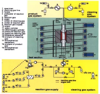
Although material development for HTR's almost ceased in Germany in 1985 development of C-based materials for Fusion Reactors continued. These included innovative concepts such as Carbon Fibre composites, and mixed materials (Si, Ti content) which show a high heat conduction and high strength. A second series of experiments are therefore planned to look at the performance of such materials under accident typical temperatures (about 1273 °K) in steam and in air. The experimental work involves the THERA test rig and the use of induction heated tube shaped samples in the induction furnace facility INDEX (Figure 4). Oxidised gas flows through the inner bore hole of the tube with flow rates sufficiently high to suppress the influence of boundary layer mass transfer on kinetics. Oxidation effects are measured by mass spectrometric analysis of the product gases and by weight loss of the sample. Experiments are also planned for measurements of CFC materials irradiated and non-irradiated (up to ldpa) that will look at strength, dimensional change, thermal diffusivity and heat capacity.
MATERIAL ISSUES FOR ASSURANCE OF STRUCTURAL INTEGRITY.
HTR Materials data base
The need for reliable material data and properties is a key issue in the development of any innovative reactor technology and is especially important for the understanding of structural integrity issues and material behaviour. It is particularly important in those areas where safety considerations are upper most. For the HTR key component materials a data base of properties is required that covers information on manufacturing provisions, products & parts, test data information and design properties. Reliable design property information is one of the main outputs and needs. Work on developing a data base is underway with considerations being given to the development of a web based facility. Design and technological issues plus omissions and shortage of test data will be the basis on which the data base will be built up and expanded and on which future R & D needs will be assessed.
HTR Reactor Pressure Vessel (RPV)
The main concerns for the vessel are expected to be at the welds. In general welds are a concern in structures because"
they are frequently the site of damage found in plant,
are often associated with defects or geometrical discontinuities,
they can result in a 'metallurgical notch' or strain concentration due to discontinuities in the properties of the weld, • at elevated temperature certain steel welds often have a lower creep ductility in comparison with the parent steel The welds of the HTR vessel carry an additional requirement to satisfy the safety analysis methodology and safety studies (defect location and defect size) and have to be assessed from the point of view of non-destructive examination and potential for failure or leakage.
The main damage mechanisms to be addressed are fracture, fatigue and creep -fatigue. These have to be evaluated from an initiation aspect and for crack growth of defects under fluctuating thermal and mechanical loads. The potential effects of environment (temperature, irradiation, ageing) all have to be taken into account. The test programme and its development addresses toughness and creep properties under as-fabricated and simulated end-of-life conditions. This will provide an understanding of the welding processes, weld metals and post-weld heat treatment required for thick welds and weld factors to be applied on the base material properties.
Other sensitive zones that are to be checked are areas that feature thicker sections (potential for reduced properties and strength), hot spots and regions important from a functionality point of view. This includes the flange area and belt line which have to satisfy primary and secondary stress limit requirements and progressive deformation mechanisms.
HTR High Temperature regions
For the high temperature regions the main structural integrity issues are concemed with the consequences of creep and the influence of the environment. Two basic requirements dictate the design of gas turbine blades and discs, the cycle temperature and the maintenance of critical dimensions (clearances) throughout the service life. The selection of turbine blade designs are often limited by the high temperature creep properties of the material (i.e. non-cooled blade).
For turbine discs there is a requirement to limit the permanent growth and distortion to within typical design life targets. This is usually achieved by maintaining a greater part of the disc cross section within elastic limits, (i.e satisfying progressive deformation or shakedown criteria). Critical regions for the disc from the point of view of potential creep and fatigue failure are the hottest parts. These are at the disc neck because of unrelieved high localised stresses giving rise to undetected growth; and at the rim, due to the additional geometric effects of the blade root slots and possibly cooling holes. Careful material selection or control of localised stress and temperature conditions can avoid creep-fatigue interaction problems in these areas.
For the turbine blades failure modes such as creep, high cycle fatigue and low cycle fatigue have to be taken into account. The gas radial temperature variation often peaks typically in the middle third of the blade with steep temperature
gradients across the blade section which vary according to the transient and steady state conditions. All regions of the blade profile therefore undergo complex stress-strain cycling with reversed plasticity in some areas. For material selection a close understanding of some important parameters such as creep rupture, creep ductility and creep rate are needed. Typically for nickel based super-alloys time dependent effects induced by creep and oxidation on cyclic crack growth rates are important for design, and hence an understanding of creep crack growth behaviour and the interaction between creep and fatigue with tensile and compressive dwells is needed. The awareness of the role of grain boundaries in high temperature fracture has also led to significant developments in single crystal super-alloys that can give beneficial anisotropic material properties.
Corrosion can cause a significant shortening of the material creep life and acceleration of creep crack growth rates. Application of suitable coatings can arrest creep reduction tendencies, however their use requires an understanding of the potential for interfacial cracking at the coating layer to avoid the development of more significant cracking from the interface.
Thermal-mechanical assessments need to take account of rotational speeds, vibration, temperature gradients and where applicable, consider the effects of geometric concentrations and localised temperature gradients. For the discs 2-D investigations can be sufficient whereas significant stresses in the transverse plane can necessitate 3-D studies for blades.
Graphite components
Generally, the most important material property change from the point of view of core lifetime integrity is dimensional change. Graphite initially shrinks but then undergoes shrinkage reversal, i.e. growth. This is referred to as 'turnaround'. The exact form of the dimensional change curve varies with irradiation temperatures. Normally, the higher the temperature the lower the peak shrinkage and the lower the dose at which turnaround occurs. Different graphites can have significantly different dimensional change curves at the same temperatures.
The validation of the through life performance of the graphite core structure is critically dependent on the knowledge of graphite properties and the way they vary under fast neutron irradiation. It is essential therefore that its behaviour is fully understood and investigated up to at least the peak design dose and over the appropriate temperature ranges The final choice of graphite for the core should therefore be based on a number of factors, although the most important will be the effects of fast neutron irradiation on it's properties up to the peak doses envisaged. Given the best graphite available, it is the task of the core designer to produce a design that will operate safely over the design life of the reactor. The most important considerations are component integrity and changes in core geometry, both of which are affected by the dimensional change. For example, graphite shrinkage could lead to disengagement of individual components and between the core and interfacing structures and to a loss of control of the core geometry; graphite growth could lead to the take-up of design clearances and large forces between structures; and differential shrinkage/growth in a component could lead to high stresses and failure by cracking.
SUMMARY AND CONCLUSIONS
The need for reliable material data and properties is a key issue in the development of HTR technology and is especially important for those areas where safety considerations are upper-most. The HTR-M project aims to provide a firm materials platform on which to develop the future HTR technological basis within Europe and provide a first step towards building an understanding of the behaviour and manufacturing requirements for some of the new materials that will be needed for such developments. The objective is to improve knowledge of materials for future HTR's for the reactor pressure vessel, the control rod and turbine (blades & discs) and the reactor graphite. The HTR-M project extends over a period of four years and is being performed with the support of the European Union Fifth Framework Programme. The project is also being co- ordinated through the direction of a European HTR Technology Network (HTR-TN). This paper outlines the HTR-M work program and reviews important issues concerning material needs for feasibility and assurance of structural integrity.
REFERENCES
1. W. Von Lensa, D. Hittner, J. Guidez, F. Sevini, A. Chevalier, M. T. Dominguez, G. Brinkmann, T. J. Abram,
J. Martin- Bermejo, "The Role of International Collaboration within the European High-Temperature Reactor Technology Network (HTR-TN)" Seminar on HTGR Application and Development, Beijing, China, March 19-21,2001.
2. J. Guidez, "Europe needs the HTR", Nuclear Engineering International, October 2000
3. Graphite Specialists Meeting, Oak Ridge National Laboratory, Oak Ridge, TN, USA, September 5-6, 2000
ACKNOWLEDGEMENTS
H T R - M - Materials for the High T e m p e r a t u r e R e a c t o r
WP1 Vessel Materials
Review of existing RPV materials used on gas cooled and other types of reactors
Establish a data base for RPV steels at low and elevated temperatures
Tests on steel RPV welded joints: tensile / creep, cross weld, creep / fatigue, fracture as required.
Tensile / creep fracture tests as required on specimens irradiated in HFR at NRG Synthesis of results
WP 2 High Temperature Materials Internal Structures
Identification of materials with high potential interest and compilation of existing data. Selection of the most promising grades for further R&D effort.
Development and testing of available alloys to meet HTR requirements
Test work concentrates on control rod cladding materials. Mechanical/creep tests at temperatures up to 1100 °C in facility at CEA.
WP 2 High Temperature Materials Turbine
Identification of the materials with high potential interest and a compilation of existing data Selection of promising grades for further R&D Development and testing of available alloys to meet HTR requirements
Test work concentrates on turbine disc and blade materials. Short term tensile / creep tests (air, vacuum) from 850 to 1300 °C, Fatigue tests at 1000 °C at CEA. Creep & creep / fatigue tests in Helium at JRC on a serve hydraulic test rig.
WP 3 Graphite
State of the art and first version of data base of properties
Assess requirement for new graphites and needs of future HTR's
Tests to obtain kinetic data on fuel matrix & structural graphite in oxygen (823 and 1023°K-
partial pressures 2 & 20 kPa - using thermo- gravimetric facility THERA at FZJ.
Testing of oxygen resistance of advanced C- based materials (CFC's, doped materials, SiC)
- steam & air using oxidation facility INDEX of
FZJ
Figure I S u m m a r y of H T R - M W o r k P r o g r a m
200
150
-~ 100
%
50
~ l a L_,r-I ~.r] ~I~ Lr
I
----M-- SA 516-70I:1 SA 508
---A-- 2.25 Cr-1Mo (RCC-
MR)
, Mod 9Cr- 1Mo (EFR)
. I . L .
100 200
%
300 400 500 600
Temperature °C
Material
Ferritic
Austenitic
(Ferritic steel) Austenitic steel & Nickel based Alloys
Nickel based Alloys
time independent properties time dependent properties
Projects
~ J a p a n e s e Project ~ He / He heat exchanger)
~ P N P (He / He heat exchanger)
~ P N P (reformer furnace tubes) I!~i~!i~ii~i~i~ii~iiiii~iii~iiiiiii
~ H H T (hot duct, turbine blades)
/
' I T H T R (steam generator)~ F S V ( steam generator)
I~!i~,~i~]~i~iilAVR (steam generator) ~ i ~ 1
I I I I I I I I I t I I I
I0 100 200 300 400 500 600 700 800 900 1000 1100 1200
i
~ K T A Rules ~ A
IIIIIIIII111111t1111111 IIIIIIIASME Code Section III I
li::iiiiiiiiii::ii!iiiii!iiiiiiiiiii::iii!i!ii!iiii!iiiilmRD - Rules [:iii!iiiiiii•iiiiiiiiiiiiiiiiiii•••iiiiiiiiiiiiiiiiii•iiiiiiiiiiiiiii•iiiiii!•iiiii!iiiiiiiiiiiiiiiiiiiiiiiiii•iiiiiiii!•ii!!iii•i]
Design Code ~ A D - Rules ~ ~
~ ~ A S M E Code Section NH I
l IRCC-MI
~i~i!~i~!~!, RCC-M R ... ; ...
ITemperature °C
Figure 3 Materials Temperature Versus Design Code Temperatures
I speci.rnen
clean =ng gas line 1 7
3 heater
4 preheater of r e a l i g n p r o d u c t
gas g a s system
5 reaction gas 6 argon
7 cooler of cleaning gas
8 cooler of reaction gas water
9 reaction gas supply ~ 1 ~
10 argon ...
11 argon cylinder m l " 12 cleaning gas cylinder
ig!
13 pressure reachon gas 14 pressure cleaning gas
15 difference pressu re
16 analysis of cleaning gas
17 atmospherical ~"
settlement
16 analysis of product . g a s
19 atmospherical
settlement
Igl 11
ArS.0
ArS.0
0 2 4.5
:itest/;-Nctlon ; i ! ; ~ i ¸
c l e a n i n g g a s s y s t e m
j ....
!,,.'ili
I>TCl I
--- reacdtlon gas line argon line
Ar 5.0
reaction gas supply cleaning gas system