18th International Conference on Structural Mechanics in Reactor Technology (SMiRT 18) Beijing, China, August 7-12, 2005 SMiRT18-K16-2
MASS-SPRING MODEL USED TO SIMULATE THE SLOSHING OF
FLUID IN THE CONTAINER UNDER THE EARTHQUAKE
Jing Wen*
China Institute of Atomic Energy, Beijing
Phone: 69358491, Fax: 69358472
E-mail: [email protected]
Lin Luan
China Institute of Atomic Energy, Beijing
Daogang Lu
North China Electric Power University,
Beijing
Xiaoan Gao
China Institute of Atomic Energy, Beijing
Shuangwang Zhang
Beijing Institute of Nuclear Energy, Beijing
Wei Wang
China Institute of Atomic Energy, Beijing
ABSTRACT
A lumped-mass spring model is given to simulated the sloshing of liquid in the container under the earthquake in the ASCE 4-86. A new mass-spring model is developed in the 3D finite element model instead of beam model in this paper. The stresses corresponding to the sloshing mass could be given directly, which avoids the construction of beam model.
This paper presents 3-D Mass-Spring Model for the total overturning moment as well as an example of the model. Moreover the mass-spring models for the overturning moment to the sides and to the bottom of the container are constructed respectively.
Keywords: 3-D Mass-Spring Model, Seismic Analysis, Sloshing, ASCE 4-86
1. FOREWORD
The fluid in the container interacts with the container structure under the earthquake, and the bottom and the side walls are subjected to the pressure because of the fluid sloshing. This pressure is called hydrodynamic pressure. The Lumped Mass-Spring Model(LMSM) is presented in “Seismic Analysis of Safety related Nuclear Structures and Commentary on Standard for Seismic Analysis of Safety related Nuclear Structures”[1](ASCE 4-86). This model, which is simple but valid, is described in detail. This paper develops 3-D mass-spring model based on the LMSM in the ASCE4-86. Moreover, the mass-spring model linked to the bottom of the container is given to simulated the pressure on the bottom.
2. COMPUTATION FORMULATIONS FOR MASS-SPRING MODEL
assumptions cited in that model: a, The fluid is incompressible, inviscid and irrotational. b, The container has rigid vertical side walls and horizontal bottom. c, Fluid motion only in vertical direction and horizontal seismic (excitation) direction is studied, and the motion in the orthogonal horizontal direction can be neglected. d, Only the first modal shape is considered for fluid sloshing. Housner Model has some advantages: simple-formed resolve and enough accuracy. This paper involves in only the mass-spring model and corresponding parameters related to fluid sloshing.
2.1 UPSTANDING CYLINDRICAL LIQUID-STORAGE TANK
The mass-spring model is shown as Fig.1. This model is used to simulate the fluid sloshing in the upstanding cylindrical liquid-storage tank. And R is inner radius of the tank, h is the height from the bottom of the tank to the liquid surface. MI and HI are impulsive mass and the height of the center of impulsive mass related to the
impulsive pressure respectively. MC and KC are convective mass and the height of the center of convective mass
related to the convective pressure respectively. KC is the stiffness of the spring. The vibration direction of the
mass MC-KC system corresponds to the seismic direction. The fluid motion can not be excited on the horizontal
direction by the orthogonal horizontal direction. The corresponding equations mostly refers to reference [3]. Convective mass is
= h R h R M
MC F
8 27 tanh 8 27 12 11 4 1 2
Eq. 1 2R
HC
HI
MC KC
MI
x
Seismic Direction
h where MF is the total mass of the fluid.
The total force of the convective pressure on the side walls is
t R
Sw πρϖ θ sinω
48 11 0 4 2 −
= Eq. 2
where ρ is the density of the fluid, tis time, ωis the first natural frequency of the fluid’s sloshing, and is the circular amplitude of the first modal shape (only the first modal shape considered). ω is given by
0 θ = R h R g 8 27 tanh 8 27 2
ω Eq. 3
Fig.1 Simplified model of upstanding
cylindrical liquid-storage tank
where g is the gravity acceleration (9.8 m/s2).
0
θ is determined by
R d
= 0
θ Eq. 4
where d, the maximum displacement of the water surface (i.e. wave amplitude), can be determined as Epstein formulation[4] R g A d
=0.837 * Eq. 5
whereA* is the floor response spectrum corresponding to the circular frequencyω.
The convective pressure on the side walls and the bottom induces overturning moments at the bottom of the container. If only considering the overturning moment at the bottom induced by the convective pressure on the side walls, the height of mass center is shown as
− − = R h R h R h h HC 8 27 sinh 8 27 1 8 27 cosh
1 Eq. 6
and the overturning moment at the bottom induced by the convective pressure on the bottom is
t h
R
Mb πρω θ sinω
27 8 3 96 19 0 5 2
If considering the overturning moments at the bottom induced by the convective pressure both on the side walls and the bottom, the height of the convective mass center should be elevated. And the height can be given as − − = R h R h R h h HC 8 27 sinh 8 27 2 8 27 cosh 1
' Eq. 8
The stiffness of the spring is determined as follows:
C
C M
K =ω2 Eq. 9
2. 2 RECTANGLE LIQUID-STORAGE TANK
The mass-spring model of the rectangle liquid-storage tank is shown as Fig.2. The parameter a is the length of the side of the tank along the seismic direction. And the other notations are similar with those in the Fig.1. And the corresponding equations are as follows:
Convective mass is
a h h
a M
MC F tanh 10
12 10
= Eq.10
HI
a
HC
MC
MI h
Seismic Direction
KC
The total force of the convective pressure on the side walls is
t a
Sw ρ ω θ sinω 12 0
2 3 =
Eq. 11
where
ρ
is the density of the fluid per unit thickness.ω
is given by = a h a g 10 tanh 10 2 ω Eq.12
and
θ
0 is determined byFig.2 Simplified model of rectangle
liquid-storage tank
a
d
2
0=
θ
Eq. 13d can be given by the following Epstein equation[4]:
ag A d 2 * = Eq. 14
If only considering the overturning moment at the bottom induced by the convective pressure on the side walls, the height of mass center is shown as
− − = a h a h a h h HC 10 sinh 10 1 10 cosh
1 Eq.15
and the overturning moment at the bottom induced by the convective pressure on the bottom is
t
a h a
Mb ρω θ sinω
10 sinh 120 10 0 4 2
= Eq.16
− −
=
a h
a h
a h
h
HC
10 sinh 10
2 10 cosh 1
' Eq. 17
The stiffness of the spring is presented as follows:
C
C M
K =ω2 Eq. 18
We can see that all the parameters are related to the length a from the above-mentioned equations and expressions. The lengths of the two adjacent sides of the rectangle tank are may different. As a result, the parameters and variables on the two orthogonal horizontal direction , MC, HC, , KC, and , are may different.
'
C H
3. BRIEF INTRODUCTION OF THE MODEL IN ASCE 4-86
A lumped-mass stick model is presented to simulate the sloshing of the fluid in ASCE 4-86 (see Fig.3). The liquid-storage tank is simplified as a beam. And the parameters of the mass and the spring are given based on the assumption of the rigid wall (as described in chapter 2). For this model the elasticity of the tank walls are considered and the solving of the problem is simplified. The explanations are as follows:
MS1 thru MS7 are tank structure masses at node 1 thru 7. MI5 thru MI7 are the impulsive fluid masses at node
5 thru 7, which are added directly on the tank. And MC is the convective fluid mass, which is linked to the sides
of the tank by the springs.
The distance from the bottom of the basin to the mass center of the convective fluid is . The distance from the mass center of the convective fluid to the water surface is h=h . The convective fluid mass is distributed equally along the height l
'
C H
'
C H
C which is twice distance from the water surface to the mass center of the
convective fluid. The convective fluid mass is rigid, which keeps the convective mass the same horizontal displacements during motion.
The springs are distributed equally along the height lC. The stiffnesses of the single spring are all k, and the
combined stiffness is equivalent to the stiffness KC. Suppose that n springs are distributed along the height lC
(n=4 in the Fig.3), k should satisfy:
C
K k
n× = Eq. 19
Seismic Direction MS3
MS2
MS1
Bottom of Basin
lC
Rigid Link Basin Attachment to Structure
lI
MS4
MS5+ MI5
MS6+ MI6
MS7+ MI7
MC
Water Surface Horizontal Springs for Convective Mass effects
Top of Basin
4. 3-D MASS-SPRING MODEL
With the developing of the computer hardware and the mechanics programs it comes to being not so difficult to compute the hydrodynamic pressure induced by the fluid’s sloshing using the 3-D finite elements model which consist of shell elements or brick elements. If developing the 3-D model based on the model shown in the Fig.3, we can obtain directly the resulting stress of the shell elements or brick elements from inputting motion, which is very convenient.
4.1 INCREASING THE NUMBER OF THE SPRINGS FOR EVERY LAYER
The 3-D mass-spring model for the cylindrical container is shown as Fig.4. The differences between it and the model in Fig.3 are as follows:
The convective fluid mass MC is equally distributed along the median axis of the cylinder. Similar to Fig.3, the same springs are equally distributed at n1 different levels along the axial height and n2 springs around the circle at one level (different from the model with only one spring at one level). And every spring is linked to the convective fluid mass along the median axis. The stiffnesses k of the distributed springs should meet:
C
K k n
n1× 2× /2= n2≥3 Eq. 20
The 3-D mass-spring model for the rectangle container is shown as Fig.5. The differences between it and the model in Fig.3 are as follows:
The convective fluid mass MC is simulated by rigid plane. The length of the plane is parallel to one side of the rectangle container and perpendicular to the seismic direction. The same springs are equally distributed at n1 different levels along the height and n2 springs on the two side planes of the container at one level. And all the springs are linked to the mass MC. The stiffnesses of all the springs should meet:
C
K k n
n1× 2× = Eq. 21
The number of the springs should not be too less to lead to excessive pseud stress concentration on the joint between the springs and the walls of the tank.
MC
k k
k k
k k
k k
Seismic Direction
Rigid Plane
Fig.5 Distribution of the springs for
rectangle liquid-storage tank (top view)
Fig.4 Distribution of the springs for
cylindrical liquid-storage tank (top view)
k k k
k k
k k k MC
4.2 SOLVING THE PRESSURE ON THE SIDES AND THE BOTTOM DIVIDUALLY
It is more consistent with the theoretic analysis to construct the mass-spring model on the bottom to simulate the convective pressure on the bottom. The overturning moment at the bottom induced by the fluid sloshing in the models shown as Fig.3 thru Fig.5 is simulated by lengthening the arm of force (or pressure) on the side walls, which increases the pressure on the sides out of expectation. It could be solved in the 3-D model. On one hand, lowering the center of the convective fluid mass and replacing by ; on the other hand, constructing 3-D mass-spring model on the bottom besides on the sides.
'
C
H HC
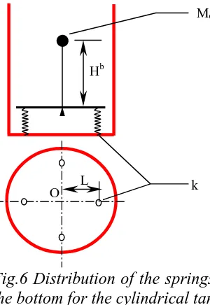
The 3-D mass-spring model on the bottom for the upstanding cylindrical liquid-storage tank is shown as Fig.6. The radius R of the horizontal circular rigid plane is equal to the inner radius of the tank. The height of the vertical rigid beam linked to the center O of the circular plane is Hb:
C c b
H H
The concentrated mass on the top end of the beam is supposed to still be MC (using conveniently the existing
results as possible ). The circular plane is superposed on the bottom of the tank (being not superposed in the figure in order to being viewed clearly). The plane and the bottom are linked through the springs. Four springs with same stiffnesses k are distributed equally around the circular plane. And the distance from any one spring to the center O of the circular plane is L. The four springs are called Elementary Spring Assembly (ESA).
Hb
L O
MC
MC
Hb
L O α
α
KC
k
k
Fig.7 Equivalent model for the springs
linked to the bottom and the sides
Fig.6 Distribution of the springs on
the bottom for the cylindrical tank
The ESA has an advantage: the moment at the bottom of the container keeps same numerical value when the circular plane rotate for angle around any one diameter of itself. Moreover, applying displacement constraint on the center O of the circular plane to keep it relative displacement zero to the bottom of the tank. The height of the center of mass MC is HC in the MC-KC system (hereinafter referred to as System MC-KC-HC )
shown as in Fig.1. and now we add one MC-KC system (hereinafter referred to as System MC-KC-Hb ) in which
the height of the mass center is Hb. The summary overturning moment at the bottom for the two systems will be equal to that for the system MC-KC-H/C. Therefore, we will construct another MC-KC system (hereinafter referred
to as System MC-KC-O) to replace the system MC-KC-Hb. and the following requirement should be meet: The
overturning moment at the bottom for the system MC-KC-O is equal to that for the system MC-KC-Hb. The two
systems are all shown as Fig.7. The stiffnesses of the springs will be determined appropriately in the following sections.
If the circular and the rigid plane rotate for angle around any one diameter of the circular plane, the moment at the bottom for the system MC-KC-Hb is:
( )
2α 1b C b
H K
M = Eq. 23 and the moment at the bottom for the system MC-KC-O is:
α
2 2 2kL
Mb =
Eq. 24
The overturning moment at the bottom for the two systems should be equal (i.e. ). we can obtain:
b b
M M1 = 2
( )
2 22 b
C H
K
kL = Eq. 25 If n sets of ESAs are constructed in the system, so
( )
22 b
n
=
( )
2 2 2 b C H K nkL = Eq. 27If only one set of ESA be constructed at L=R/2 and the stiffness k is the same, k can be determined by 2 2 = R H K k b
C Eq. 28
We should make sure that the natural frequency of the system MC-KC-O is consistent with Eq. 3. and it is
proved as follows:
From Fig.6, rotational inertia of the system MC-KC-O around O is
( )
b 2C H
M
I= Eq. 29
From Eq.18we can get the torsional stiffness of the system M C-KC-O
2 2kL
kα = Eq. 30
The circular frequency of the system can be obtained from Eq.29 and Eq.30
( )
2 2 2 0 2 b C H M kL I k = = αω Eq. 31
Introducing Eq.19we have
C C M K = 2 0
ω Eq.32
Comparing it with Eq.9, It is clear that the circular frequency of the system MC-KC-O is consistent with
Eq.3.
The setting of the springs along the radius is related to the convective pressure on the bottom of the tank. Suppose that the center of the bottom is the origin of the coordinate (refer to Fig.1), x-direction is the horizontal seismic direction, and z-direction is the other horizontal direction orthogonal to x-direction. The convective pressure can be given by theoretic analysis[3]:
t R z R x R x R x R h R
pb ρω θ sinω
4 1 3 1 8 27 sinh 8 3 0 2 3 2 2 − −
= Eq.33
The overturning moment at the bottom induced by the pressure Pb on the annular arear1 r2 can be presented as follows:
2 1 2 1 2 4 24 5
1 ξξ
ξ ξ ξ ξ − =A Mb Eq.34
where A is coefficient unrelated to ξ, and
R r R r R r 2 2 1 1 , , = = = ξ ξ
ξ where r∈
[
0,R]
and ξ∈[ ]
0,1.If laying one set of ESA at r1=0.5R (first one set) and r2=R (second one set) respectively, we can get the
ratio of the overturning moment of the second one to that of the first one from Eq.24:
1 2 4 k k =
η Eq. 35
where k1 is the stiffness of the single spring of the first one set ESA, and k2 that of the second one.
−
−
= 0.5
0 2 4
1 5 . 0 2 4
24 5 1 24
5
1 ξ ξ ξ
ξ
η =12.4 Eq. 36
Comparing Eq.35 with Eq.36, we can get:
k2 =3.1k1 Eq.37 Introducing it into Eq.26, we obtain
2 2
2
1 0.15 0.46
=
=
R H K k
R H K k
b C b
C (Eq.38)
Similarly, if laying two sets of ESAs at r2=R and the stiffnesses of all the springs are the same, we can get:
2
2 0.23
=
R H K k
b
C Eq. 39
If laying one set of ESA at r1( to be determined) and r2=R respectively and the stiffnesses of all the springs
are the same, we can get:
R
r1=0.7562
2 2
1 0.318
=
= =
R H K k
k
b C
k Eq. 40
If laying one set of ESA at r1=0.25R, r2=0.5R, r3=0.75R and r4=R respectively, we can get:
2 1 0.0391
=
R H K k
b
C k2 =3.5k1 k3=6.3k1 k4 =8.3k1 Eq. 41
This paper will not describe the mass-spring model on the bottom for the rectangle tank in detail. 5. APPLICATION EXAMPLE
The example is given in Fig.8. We used the 3-D mass-spring model in the chapter4.1 to simulate the convective pressure of the one liquid-storage tank in China Experiment Fast Reactor (CEFR). The springs are distributed equally on 6 levels along the height which is determined by Eq.8 and 8 springs around the circle plane at any one level. The 8 springs at any one level are all linked to the mass (MC/6) located on the median axis
of the cylinder. Moreover, as one complete analysis, the impulsive pressure, vertical seism and the other load should be considered, which is not described in detail.
Support of container container wall added
impulsive mass spring
Convective mass After computation we have checked whether the
vibration frequency of the fluid is consistent with Eq.4 and whether the summary force on the springs Is consistent with Eq.2.
walls is 100% 1.5% 3
. 617
3 . 617 4 .
626 − × =
. So we can say that the results of 3-D mass-spring model by FEM agree with those by theoretic analysis very well and that developing the mass-spring model in ASCE 4-86 to 3-D mass-spring model is effective and valid.
6. CONCLUSIONS
A simple and effective mass-spring model is given to simulated the hydrodynamic pressure of the liquid in the container under the earthquake in the ASCE 4-86. This paper presents a method to develop the model of hydrodynamic pressure to 3-D mass-spring model and gives the mass-spring model linked directly to the bottom of the container. The model presented in this paper is theoretically effective and valid and can be used directly in 3-D model.
REFERENCES
[1] American Society of Civil Engineers, (1986), Seismic Analysis of Safety related Nuclear Structures and Commentary on Standard for Seismic Analysis of Safety related Nuclear Structures, pp.9-17
[2] G. W. Housner, (1957), Dynamic Pressures on Accelerated Fluid Containers, Bull. Seism. Soc. Am., vol. 47, No.1, pp.15-35
[3] JU Rongchu, ZENG Xinchuan,(1983), Couple vibration theory of elastic structure and liquid, pp.40-138 [4] H. I. Epstein, (1976), Seismic Design of Liquid-Storage Tanks, Journal of the Structural Division, Proc. of