Energy Conservation by Dynamic Cell Shape
Implementation
Nikita Shaw
P.G. Student, Department of Computer Science Engineering, Kalyani Government Engineering College, Kalyani, West Bengal, India
ABSTRACT: During the last decade, there has been tremendous growth in cellular networks market. The number of subscribers and demand for the cellular traffic has escalated astronomically. Mobile networks of the future will be energy sober with energy consumption proportional to traffic. So operators are searching for different means to meet these new demands in wireless cellular networks along with keeping the cost optimized. Such unprecedented growth in the cellular industry has pushed the limits of energy consumption in wireless networks. Mobile networks are vital to the 2000 W society and must be simple and reliable. In this project work the approach for base station dynamic shape scheduling has been used to decrease the work consumption rate.
A new scheme is used in this paper which signifies the use of dynamic change in shape of base station. This method is an extension of cell zooming approach.[13] The conventional cell shape i.e. hexagonal shape takes the predefined energy. The different shapes which are proposed in this paper are circular, square and triangular. Depending on the shapes which will be implemented dynamically the result shows how much less power will be needed for serving that area and even same power will be required, that area will be served efficiently with good service. The simulation results of the energy consumption in different shapes are shown in different graph.
KEYWORDS:Cellular Network,Base Station Subsystem (BSS), Mobile Unit (MU), Base Station (BS).
I. INTRODUCTION
In cellular networks traffic load may have significant spatial and temporal fluctuations due to various reasons. The reasons may be user mobility and undecidable nature of many data applications. The users have dynamic nature and movement in their daily lifestyle and everyday in some peak hours the users have different population (density) in different areas. For example, for a cellular network in a city, the traffic load in the daytime is relatively heavy in office areas and light in residential areas, while the opposite things happen in the evening. If the capacity is planned based on the peak traffic load for each cell, there are always some cells under light load, while others are under heavy load. In this case, any static cell deployment will not be optimal for such traffic load fluctuates. So any user should be served by at least one base station keeping energy conservations optimized [6]. Sometimes some base stations can be switched off also because of their having very light load [17-20]. Traffic load fluctuations can be even more serious as the next generation cellular networks move towards smaller cells such as micro cells, Pico-cells, and femto-cells, which make the cell deployment even harder.[4]
II. CELLULAR NETWORK
Cellular networks mainly consist of two parts: the radio access network or base station subsystem (BSS) and the core network, which are connected through a backhaul connection.
1. Base Station Subsystem (BSS):
The base station subsystem is responsible for handling traffic and signalling between the core network and the user. It consists of a network of base station transceivers grouped under several base station controllers which are connected to the core network.
2. Mobile phones/Mobile Unit (MU):
A GSM mobile phone is made up of two components which are the mobile or radio telephone and the SIM card (Subscriber Identity Module). This allows making a distinction between user and mobile terminal in a GSM network. The mobile radio cellular system is characterized by its international unique serial number which is global or International Mobile Equipment Identity (IMEI). The users are identified by their customer number (International Mobile Subscriber Identity or IMSI), which is stored in the SIM card. It is assigned to the subscriber when he/she registers with the respective network provider distinguished from the telephone number assigned to the user, which is Mobile Station ISDN Number (MSISDN).
The subscriber-specific call numbers are also stored on the equipped the SIM card. Different cryptographic algorithms for various authentication and encryption of user information are also implemented in the SIM card. In addition, text messages, call charge etc information and a telephone directory can also be stored in the SIM card too.
3. Base Station (BS):
A GSM’s Base Transceiving Station (BTS) consists of the interface between the network provider and the mobile phone, it contains transmit and receive equipment. For example, the channels for providing signals and for payload traffic are provided by BTS and the data traffic between BTS and MSC is also controlled here.
4. Mobile Switching Centre (MSC):
Several base stations are controlled by the Mobile Switching Centre (MSC). This switching node controls all the technical functions of a landline network’s switching node, for example, path search, and proper signal path switching and processing of several supplementary services. In case there arises any need for a connection to a subscriber in the landline network, it is forwarded by the MSC to the proper landline network through a switching path.
If a network provider is in a condition to provide all services for which demand arises, it must store different items of data. For example, it is necessary to know about the subscribers using the network and the services they wish to avail such as the name of the subscriber, corresponding customer number and the services of interest of the user, is stored in a register which is Home Location Register (HLR). For establishing any kind of connection the network provider should know the current location of the subscriber and whether his mobile phone is switched on or not. This information is stored in the Visitor Location Register (VLR) and the HLR.
The network provider may also maintain another register which is Equipment Identity Register (EIR), holding details of all mobile transceivers permitted by network, which is broken down into three groups which is known as the white list, grey list and black lists. The white list is the register of all mobile phones which are functioning properly and reliably, the grey list contains all phones which are possibly defective, while the black list holds information of all phones having a fault or having been reported as stolen.
III.ENERGY CONSERVATION
Energy consumption has become one of the most important issues in the world, as the carbon emissions of energy sources have great negative impact on the environment, and the price of energy is also increasing. The large number of BSs contributes a major portion of the energy consumption of cellular networks. When a BS is in its working mode, the energy consumption of processing circuits and air conditioner takes up about 60 percent of the total consumption. Therefore, by merely controlling the transmit power of radio equipments, the effect of energy saving is marginal. However, most of the efforts for energy saving in cellular networks still focus on reducing the transmit power of BSs and MUs. To save the energy of the whole network, the phenomenon of traffic load fluctuation implies that some BSs can be switched off when the traffic load is light.
Cell size is generally static. But it can be made dynamic by using Cell Zooming technique which adaptively adjusts the cell size. [13] By using cell zooming and base station scheduling algorithm, we can save energy. Considering layouts in different size of cell the authors has introduced the concept of area power consumption as a system performance metric. [2]
Simulation result suggests that under different traffic scenarios, this approach is useful.
In this paper the approach of dynamic shape change of cell is used. This idea reduces the overall consumption of a single base station to a very significant amount.
IV.CELL SHAPE IMPLEMENTATION
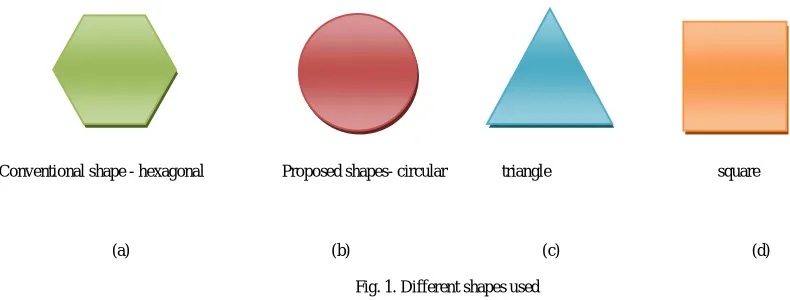
An example of cell shape implementation has been shown below
(a) (b) (c) (d)
Fig. 1. Different shapes used
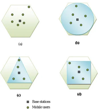
If the users make population in a particular shape then the corresponding shape should be implemented by the cell i.e. changing from conventional hexagonal shape to that particular shape. Hence it is clearly visible from the figure 2 that how much less area will be covered. So less power will be consumed or area can be served with good power density.
Proposed shapes- circular triangle square
Fig. 2. Representation of benefits of different cell shapes over conventional shape (a) Conventional hexagonal shape (b) Circular shape benefit (c) Triangular shape benefit (d) Square shape benefit
Cell shaping can be implemented by using a cell shape server (CSS). Cell shape server may be standalone or its functionality may be added to other existing entity or it may be virtual as well. A cell shape server will be in charge of the cell shape change decision of a number of base stations. Each base station will have three working states, Active, Passive and dynamic shape (DS).
CSS will collect information (Current Load, Maximum Load, Current Traffic etc) from each base station under its control. Then CSS will analyse these information to see if there is any scope to make some base station passive to save some energy. CSS will calculate new values for the existing parameters of the base stations. After that CSS will send its final decision to each base station with their new parameter values.
(a)
(b)
(c)
(d)
V. CELL SHAPE IMPLEMENTING TECHNIQUE
The real implementation of this technique can be done by change in angle of antenna beam tilt for different directions or angles [10] also the energy density, S, at a distance, R, from the antenna is given by the following equation ,
=
A simple and straight forward way is to adjust the physical parameters such as the transmit power of BSs. Besides physical adjustment, other techniques can also be used for cell shape implementation.
1. Physical Adjustment:
Adjusting physical parameters of network deployment can help to implement cell shape. Cells can zoom out to the required degree up to required angle by increasing the transmit power of BS, and vice versa. Furthermore, antenna height and antenna tilt of BSs can also be adjusted for cells to zoom in or zoom out in the particular degree and angle [9]. Such adjustments need help of additional mechanical instruments.
2. BS Cooperation:
In BS cooperation multiple BSs collectively form a cluster. It is also called as Coordinated Multi-Point (CoMP) transmit/receive in 3GPP Long Term Evolution Advanced (LTEA) [17]. Within the cluster, mobile units are serviced cooperatively by the respective base stations which are forming the cluster.
3. Relaying:
Relay can be used to extend the coverage of base stations.[16] Relays can be added to network which do not require any extra connections to electrical infrastructure nor to the internet and they can be placed anywhere in the network system.[14,15] Actually relays are deployed to improve QOS at the cell boundary area. Relay can also be used for cell shape implementation.
Fig.2.Techniques to implement cell shaping (a) Cell zooms in or zooms out with physical adjustments[13] (b) Cell maintains shape through cell shape server
Base Station
(a)
VI.EXPERIMENTAL RESULTS
The output result of this approach with compare to conventional method is shown below.
Power density is usually expressed in mill watts per square cm. That's nothing more than for converting the power and range to the proper units.
Power density from radar,
is either peak or average power depending on how is to be specified. =Transmitter Power
R = Range from Antenna (i.e. radius of sphere)
is the power density from an isotropic antenna multiplied by the radar antenna gain. [11] The given equation is for an isotropic antenna which spreads its signal to a spherical environment. The equation can be modified for the different shapes we have used. So the corresponding equations for the different shapes are as follows Circular=
Hexagonal=
√
Triangle=
√
Square=
The standard parameters values are 100 watts = 1 x 10 watts = 1 x 10 mW 100 feet = 30.4785 meters = 3047.85 cm.
For 100 feet i.e. 30 meters serving 100 watts of power is required. So for 1 meter serving keeping the gain 10 and power density constant, the required power for 30 meters in each case
∗10
. Watts/m2
So for11310 m2 area 100 watts energy is sufficient. So for 1 m2 area power required =0.088 watts. [11]
Fig.3.power consumption in use of different shapes i.e. energy vs. number of base station
VII. CONCLUSION
The implementation of the Decentralized Algorithm for the application of the above idea will show the benefit of the approach. The approach will work on decentralized procedure, whatever be the size of the network it will be fragmented into parts randomly. The above implementation is done based on the real time calculation strategies mentioned in different reference papers and measurement parameters. Depending on the distance on peak hour from the mobile unit (MU), the base station will implement the shape depending on several calculation and measurement parameters, which is to be done as further part of this approach.
REFERENCES
[1] Angelos Chatzipapas, Sara Alouf, Vincenzo Mancuso On the Minimization of Power Consumption in Base Stations using on/off Power Amplifiers
[2] [F. Richter, A. J. Fehske, and G. P Fettweis, “Energy Efficiency Aspects of Base Station Deployment Strategies for Cellular Networks,” 2009 IEEE 70th Vehicular Technology Conference Fall (VTC 2009-Fall), pp.1-5, 20-23 Sept. 2009.]
[3] A. Hikuma, Y. Fuke, N. Nakaninami, H. Ohyane, H. Kobayashi, Radio Base Stations Equipments toward Economical Expansion of FOMA
Coverage Areas, NTT DoCoMo. Technical Journal, Jun. 2004.
[4] Green Cellular Networks: A Survey, Some Research Issues and Challenges Ziaul Hasan, Student Member, IEEE, Hamidreza Boostanimehr, Student Member, IEEE, and Vijay K. Bhargava, Fellow, IEEE
[5] Analysis of Antenna Beam-tilt and Broadcast Coverage ,Myron D. Fanton, PE Electronics Research, Inc.
[6] Y. Bejerano and S. J. Han. Cell breathing technique for load balancing in wireless LANs. IEEE Trans. Mob.Compt., 8(6):735-749, June 2009. [7] Vodafone, Vodafone Green Technology Demo, MWC 2010, http://www.vodafone.com/content/dam/vodafone/about/sustainability/
green%20technology%20demo%20MWC%202010 PUBLIC.pps
[8] A. Hikuma, Y. Fuke, N. Nakaninami, H. Ohyane, H. Kobayashi, Radio Base Stations Equipments toward Economical Expansion of FOMA Coverage Areas, NTT DoCoMo. Technical Journal, Jun. 2004
[9] 1Akpado K.A, 2Oguejiofor O.S, 3Ezeagwu C.O, 4Okolibe A.U 1,2,3, Investigating the Impacts of Base Station Antenna Height, Tilt and Transmitter Power on Network Coverage
[10] C.A. Balanis, Antenna Theory – Analysis and Design, Harper & Row, New York, 1982.
[11] Hrishikesh Venkataraman,Gabriel-Miro Muntean “Green Mobile Devices and Networks: Energy Optimization and Scavenging Techniques’ [12] Hongyuan Zhang, Huaiyu Dai, and Quan Zhou, Base Station Cooperation for Multiuser MIMO: Joint Transmission and BS Selection [13] Zhisheng Niu, Yiqun Wu, Jie Gong, and Zexi Yang, Cell Zooming for Cost-Efficient Green Cellular Networks
[14] Banerjee, N., Corner, M. D., And Levine, B. N. An Energy-Efficient Architecture for DTN Throwboxes. In Proceedings of Infocom (May 2007).
[15] Ibrahim, M., Hanbali, A. A., and Nain, P. Delay and Resource Analysis in MANETs in Presence of Throwboxes. In Proceedings of International Symposium on Computer Performance, Modeling, Measurements, and Evaluation (2007).
[16] Relays, Base Stations, and Meshes: Enhancing Mobile Networks with Infrastructure Nilanjan Banerjee, Mark D. Corner, Don Towsley, Brian N. Levine
[17] 3GPP TR 36.814 V1.2.1, “Further Advancements for EUTRA: Physical Layer Aspects,” June 2009.