Impact of Dropped Elements on a Storage Rack
Francisco Riera(1), Joaquín Martí(1.2)and Félix Mayoral(2)
(1) Principia, Velázquez 94, 28006 Madrid, Spain <[email protected]> (2) School of Mines, Ríos Rosas 21, 28003 Madrid, Spain <[email protected]>
ABSTRACT
Storage racks for spent fuel must be able to sustain impacts caused by the accidental drop of fuel elements during handling operations. In the course of such impacts, the bottom plate of the rack should not be breached and damage should be restricted to the dropped element and the directly impacted one, if any.
The present paper deals with impact effects caused by drops of BWR fuel elements from 1.8 m above the top of the rack cells. The dropped element may impact various locations of the upper structure of the cells; alternatively, it may go through one of the cells finally to strike the bottom plate. The calculations have been carried out using explicit integration; constitutive, geometrical and contact non-linearities were carefully taken into account.
Impacts against the bottom plate resulted in the development of large plastic strains, with considerable distortion of the plate, but within the bounds allowed by the ductility of the material. Impacts on the upper edge of cell walls produced extensive tearing of the wall along two vertical lines, with progressive rolling of the torn material. Finally, impacts at cell wall intersections are obviously stiffer and give rise to less well ordered distortions than impacts against a single wall. However, the dynamics are roughly similar, with tears and distortions eventually leading to arresting the motion. Some hand approximations are also included in the paper. Their role is invaluable for providing first estimates of the phenomena and for better interpreting the numerical results.
INTRODUCTION
The problem concerns a rack for storage of boiling water reactor (BWR) fuel elements inside the spent fuel pool. Racks have to withstand a number of operational and accidental loads. The present paper evaluates the effects of postulated impacts, as arising from the accidental drop of fuel elements during operations in the pool. Elements are assumed to drop, inside the pool water, from a height 1.8 m above the top of the racks. Once dropped, the element may fall through to the bottom of a rack cell and then impact the base plate of the structure; alternatively, it may be arrested at the top of the storage cells by impact against the upper part of the cell walls. The racks must be able to absorb the energy of the impacts while:
- the bottom plate is not perforated
- loads exerted on the foot pads and lateral supports of the rack remain acceptable
- fuel cells other than those directly involved in the impact are not affected by the accident
The evaluations have been conducted using a combination of computer calculations, hand calculations and engineering judgment. The computer calculations are all finite element analyses based on explicit integration in the time domain using Lagrangian formulations; the code ABAQUS/Explicit[1] has been used for this task.
In dynamic non-linear calculations, it is not always evident whether an approximation is conservative or not. Indeed, it may be conservative from the viewpoint of certain criteria while the opposite may be true from other viewpoints. Hence, an effort has been made to use best estimates of the parameters (as opposed to upper or lower bounds), unless the conservative character of an approximation is obvious. The final results are then assessed to decide whether adequate safety exists, rather than introducing additional safety margins in each property or step of the calculation.
DESCRIPTION OF THE PROBLEM
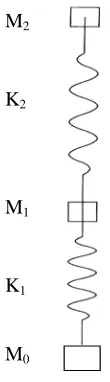
The fuel element under consideration is a GE 10x10 BWR fuel element. The distributions of masses and stiffnesses in its structure were provided by GE by means of a model composed of three masses and two springs (see Fig. 1). The values of the parameters are M0= 24.0 kg, M1= 227.8 kg, M2= 38.5 kg, K1= 223 MN/m, K2= 1.27 MN/m. We have also generated
an alternative model of the fuel element where the masses M1and M2are uniformly distributed along the 4.37 m length of
the element and the stiffness is selected to match the resonant frequency of the discrete model.
It has been assumed that the falling fuel element will not collapse or undergo plastic deformations. This is conservative because all the impact energy has to be dissipated in deformations of the impacted rack or kept as kinetic energy (rebound
SMiRT 16, Washington DC, August 2001 Paper # 1642
M0
K1
M1
K2
M2
The rack is designed to house 11x11 fuel elements within a square arrangement measuring 1.840 m x 1.840 m. The height of the storage cells is 4.271 m, with the top of their base plate located at 0.375 m above the bottom of the pool. An elevation view of the
rack can be seen in Fig. 2.
Lateral displacements and overturning are restrained by means of lateral supports built in a stiffening frame. The centres of the stiffening frame and the lateral supports are both located 3.175 m above the top of the base plate of the rack or 3.550 m above the floor level.
The rack is supported on four symmetrically arranged foot pads, located in the corners of a square with sides of 1.328 m. The base plate is 25 mm thick and is provided with a partially tapered orifice for engaging the nose of the fuel element.
The storage cells are square-section tubes, placed on a checkboard arrangement. Boral plates are disposed between any pair of adjacent fuel elements. The cells have a square inner space, 159 mm per side, and wall thicknesses of 2.3 and 2.5 mm have been analyzed. No credit will be given in the calculations to the boral (2 mm) and steel wrapper (0.5 mm). The section of the storage cells can be seen in Fig. 3.
Fig. 1. Simplified two-mass model of the fuel element
Fig. 2. Elevation view of the storage rack Fig. 3. Structure of the storage cell
The various plates and sheets of the rack are made of SA-240 Tp 304L steel; based on ASME[2], the yield stress is 173 MPa and the ultimate stress is 483 MPa, achieved for 0.39 strains. The total mass of the rack is 6154 kg, out of which 5027
kg represent the structural steel while the remaining 1127 kg correspond to the boral and wrapper of the cell walls. The fall of the fuel element takes place through water, which removes some of the energy from the drop. When the element continues to fall through one of the storage cells, confinement of the water by the cell walls provides a more effective brake. Taking into account these aspects, an impact velocity of 5 m/s has been assumed for the 1.8 m drops onto the top of the storage cells. For impacts against the base plate, velocities of 6 and 9 m/s were considered. The concerns are:
a) Survival of the foot pad and lateral support
Excessive loads on the foot pad or the lateral support could lead to failure, which is not an acceptable event. Conservative analyses of the problem should lead to loads equal or greater than the actual ones.
b) Integrity of uninvolved cells
It must be noticed that, from the viewpoint of the first criterion, it is conservative to increase the stiffness of the structures concerned (fuel element and rack structure), since this leads to shorter impacts and greater contact forces. However, from the viewpoint of the latter one, conservatism would require exaggerating the deformational consequences of the impact, which leads to softer events and smaller forces.
PRELIMINARY CONSIDERATIONS
It is convenient to start with some analytical considerations arising from simplified versions of the problems. The impact loads would be greatest (and therefore most threatening from the viewpoint of the integrity of the foot pad and of the lateral support) if all materials behaved elastically. Also, the loads exerted on the foot pad would be maximum if the cell suffering the element drop were to be that directly above the foot pad. With these assumptions, an upper bound of the impact forces can be calculated.
The model shown in Fig. 1 is approximately equivalent to a single degree-of-freedom system with a frequency f = 158 Hz. Then, conservation of momentum requires that the peak value of the impact force, assuming that the rebound velocity equals the incoming one, has the value:
f v M 2
F= π (1)
This expression yields 1.72 MN when the impact velocity v is 6 m/s and 2.58 MN when it is 9 m/s.
The representation of the element structure with a single mass or indeed with two point masses, one of which accounts for the largest portion of the total mass, is somewhat crude. One of its consequences is the sinusoidal shape of the force
history. In reality, most of the mass of the element is evenly distributed along the fuel rods. It seems therefore more appropriate to idealise the element as a rod-like structure with the correct mass and frequency. The force history now
becomes uniform in time, rather than sinusoidal. The value is: f
v M 4
F= (2)
This calculation gives 1.10 MN for an impact velocity of 6 m/s and 1.64 MN for 9 m/s.
The foot pads are designed to bear at least 1.5 MN. This means that they are likely to withstand the impact without difficulty, at least when considering the rod model. In reality, the non-linearities of the impact will lengthen the contact duration and decrease the peak force, especially for the high velocity events. This will be confirmed later by the numerical simulations.
The integrity of the lateral supports of the rack is also amenable to a conservative evaluation by hand. The peak impact force developed in the impact will be considered to act as a static load. This force will be applied in the worst storage configuration of the rack. It is then possible to calculate the lateral restraints required.
In its worst configuration, the rack would hold only ten fuel elements in its outer row. The dropped element falls through the only empty cell in that same row, thus maximising all the forces that tend to produce overturning of the rack. These
assumptions lead to a value of the force of 49.8 kN, which is the force to be jointly carried by the four lateral supports provided in the rack. This level of force is well below the design capabilities of the lateral supports.
IMPACTS ON THE BASE PLATE
The numerical analyses refine the previous hand calculations by allowing the base plate to plastify upon impact by the fuel element. Some refinements are also introduced in the fuel element model, particularly in relation with the portion that interacts with the base plate. However, to maintain the conservative character of the calculations, plastic yielding has only been allowed in the base plate.
In all cases, the base plate has been considered to be rigidly supported along the periphery of the cell. Its support, in reality, is fairly rigid, but not infinitely so. However, since the effect of interest is the load imposed on the foot pad, it is conservative to assume a greater rigidity than the actual one.
The analyses described are all axially symmetric, while the base plate is really supported on a square geometry. One of the analyses was conducted using both the two-dimensional approximation and a full three-dimensional model representing the geometry of the base plate. The differences in the impact force history were negligible.
The finite element code ABAQUS/Explicit (HKS, 1998) has been used for all the numerical calculations.
Two-Mass Model
1
2
3 1
2
3
For an impact velocity of 6 m/s, the history of impact forces (Fig. 5) has a peak value of 0.86 MN, considerably below the 1.72 MN which had been estimated by hand for the purely elastic impact; this is because the plastification of the base plate had not been accounted for in the analytical evaluation. The history can be seen to trace approximately the half-cycle sine curve mentioned previously. The 3.2 ms expected duration is lengthened to about 4.3 ms because of the yielding of the base plate.
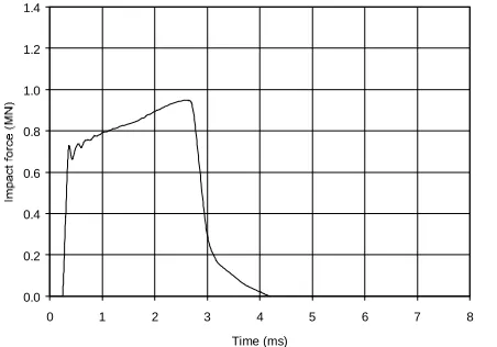
Fig. 4. Mesh used for impacts of 2-mass model Fig. 5. Impact forces with 2-mass model for v = 6 m/s on base plate
For an impact velocity of 9 m/s the impact force grows to 1.20 MN, versus the elastically calculated 2.58 MN. The impact duration increases to slightly beyond 5 ms. The rest of the observations are qualitatively similar to the previous ones.
The evolving energy balances show that the total energy is preserved in both impacts. In the 6 m/s impact, about 57% of the energy is dissipated in plastic deformations of the base plate. The fraction increases to about 69% in the 9 m/s impacts.
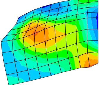
The plastic deformations of the base plate are indeed considerable. For the lower velocity impact, the peak value is slightly over 9%; at the higher velocity, plastic deformations of the base plate reach a maximum of 19% (Fig. 6). The level of plastic strain developed in the high velocity impact is below the ductility of the material, but the impact energy could not increase much further without posing a serious threat to the integrity of the base plate.
Elastic Bar Model
The previous model was used for the base plate and the nose of the fuel element, but employing the elastic bar for the rest of the element.
The history of impact forces for the 6 m/s impact can be seen in Fig. 7. The duration is not very different from the previous section, since both models resonate at about the same frequency. The peak value of the force is now about 0.95 MN. The differences with the discrete mass model (Fig. 5) can be partly explained by differences in the higher frequency response of the two models. However, the soft link to the upper mass in the discrete mass model delays the effects of its presence until very late times, when the impact has essentially finished; this is a reason why the discrete mass model actually results now in lower force levels than the elastic bar model, in contrast with the elastic hand evaluations.
Fig. 6. Plastic deformations in the base plate for v = 9 m/s
Similar information is shown in Fig. 8 for the 9 m/s impact; the peak force developed is now 1,25 MN, which is again slightly greater than the result from the discrete mass model, but well below the elastic estimates.
0.0 0.2 0.4 0.6 0.8 1.0 1.2 1.4
0 1 2 3 4 5 6 7 8
Plastic energy dissipation grows steadily to reach a value of 84% of the initial kinetic energy in the 6 m/s event and 89% in the 9 m/s impact. The peak plastic strains developed are somewhat greater than calculated with the two-mass model; they now peak at about 12% and 22% for the two impact velocities considered.
Fig. 7. Impact forces with bar model for v = 6 m/s Fig. 8. Impact forces with bar model for v = 9 m/s As a consequence of plastic energy dissipation, rebound velocities are considerably smaller than the initial velocity. Since rebound phenomena are essentially governed by elastic unloading, the velocities are about 2 m/s in all cases, irrespective of the type of model and its initial velocity.
Forces on the Foot Pad
The results obtained are summarised in Table 1. The table clearly indicates that foot pads designed for 1.5 MN forces should experience no problems as a consequence of the impacts studied. It also confirms that, as the impact becomes more elastic, the linear hand approximations become more precise; however, for more demanding impact conditions, the plastification of the base plate limits the impact forces that can be developed and the conservatism of the hand calculations grows rapidly.
Impact force (MN) Element
model
Impact velocity
(m/s) Hand calcs. FE calcs.
2-mass 6
9
1.72 2.58
0.86 1.20
elastic bar 6
9
1.10 1.64
0.95 1.25 Table 1. Forces imposed on the foot pad
Clearly, reality is closer to the results of the finite element method, which can account for the plastification of the base plate. Also, employing the elastic bar model for the fuel element constitutes a better representation of the dynamics of the dropped mass. The behaviour of the dropped element is likely to depart considerably from linearity, especially at the higher impact speeds. However, neglecting this effect makes the results conservative for the survival of the rack.
IMPACTS AT THE TOP OF THE CELLS
The dropped fuel element now impacts the top of the cell walls with a velocity of 5 m/s. The vertical attitude is the only one worth considering for the dropped fuel elements, since other attitudes lead to less damaging impacts.
Impacts on Cell Walls
The dropped element falls on the centre of one of the cell walls. The impact is much softer than those against the base plate, since the resisting thickness of the cell wall is only 2.3 or 2.5 mm; the possible strength contributions of the boral and
0.0 0.2 0.4 0.6 0.8 1.0 1.2 1.4
0 1 2 3 4 5 6 7 8
Time (ms)
0.0 0.2 0.4 0.6 0.8 1.0 1.2 1.4
0 1 2 3 4 5 6 7 8
0 10 20 30 40 50 60
0 10 20 30 40 50 60 70 80
Time (ms)
correspondingly smaller. This impact is of little concern from the viewpoint of the demands imposed either on the foot pad or on the lateral supports; the analysis is conducted only to assess the damage caused to the cell structure.
The dropped element has been modelled as a nose with little deformability followed by a bar. The nose has the mass of the lower tie rod and is assumed to be cylindrical with a diameter of 89 mm. The rest of the mass of the fuel element is in the elastic bar that follows. The frequency of the element is of lesser importance here, since the cell wall is considerably more deformable than the element.
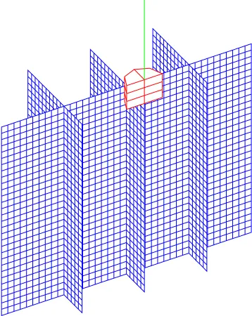
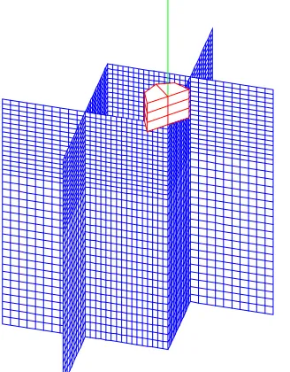
A portion of the rack has been modelled using shell elements. When building the mesh (see Fig. 9), use has been made of the vertical plane of symmetry which runs perpendicular to the impacted wall; no other symmetries have been incorporated to avoid introducing artificial limitations to the development of buckling modes. The model uses 3194 shell elements and 3337 nodes. Selected analyses have been repeated with different mesh refinement to ensure a reasonable degree of objectivity.
Lateral boundaries have been placed sufficiently far that they do not influence the analysis, which produces effects of an essentially localised nature. The nodes on the outer and bottom edges of the model are considered fixed.
The material of the shell has the properties given earlier. When the ductility of 39% is reached, elements break and cease contributing any strength to the process.
The problem starts with the fuel element impacting the top of the wall. The wall opposes a force which progressively decelerates the fuel
element; the force suffers oscillations associated with the folding and tearing of the storage cell wall. Fig. 10 presents the history of forces developed between the fuel element and the cell wall. The initial peak
is very short-lived, as the wall immediately buckles. Afterwords, the force can be seen to average about 15 kN, which requires some 60 ms
to arrest the dropped element, while crushing nearly 13 cm of the upper region of the cell wall.
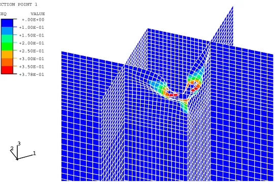
A detail of the deformations caused by the impact can be seen in Fig. 11, which confirms the very local character of the effects and the fact that neighbouring cells remain essentially unaffected. Broken elements have been removed from the mesh for easier visualisation. Fig. 9. Mesh used for impacts on shell walls
No provisions have been made to handle the contacts of the wall with itself; this is responsible for the paradoxical view in which the rolled down wall is going across itself. This simplifies the numerical calculations, while the wall response is slightly softer than would be if the contacts and their associated friction had been taken into account.
-5 -4 -3 -2 -1 0 1
0 10 20 30 40 50 60 70 80 90
Time (ms)
Top
Mid-element
Bottom
Finally, the velocities of three points within the fuel element are presented in Fig. 12. They show the gradual deceleration of the fuel element with the superimposed vibrations of this structure; it is clear that the internal dynamics of the fuel element are of little relevance in this impact.
Impacts on Cell Contacts
Impacts on the intersection of the walls of neighbouring cells have also been analysed, even though damage is likely to be shallower. The fuel element drops with its axis coinciding with the contact between the walls of two cells.
The mesh followed the same criteria used earlier (Fig. 13); it comprises 3770 shell elements and 3892 nodes. Again, analyses were repeated with different mesh refinements in order to ensure the reliability of the results obtained. Boundary conditions also follow similar criteria.
The response of the rack is considerably stiffer when impacted at the intersection of cell walls. This is clearly shown in the history of impact forces (Fig. 14); forces now average some 40 kN over the contact duration, which is only about 23 ms. The length of cell walls crushed by the dropped element is approximately 6 cm.
Fig. 12. Impact on cell walls. Velocities
Fig. 13. Mesh used for impacts on cell contacts Fig. 14. Impact on cell contacts. Impact forces
The distortions produced by the impact are presented in Fig. 15. As can be seen, they are large but extend only locally, thus leaving neighbouring cells unaffected by the impact.
CONCLUSIONS
Analyses have been conducted of the impacts arising from postulated drops of fuel elements onto a storage rack, both against the top of the cell walls and against the base plate. The analyses indicate that the rack design is adequate. More specifically:
0 10 20 30 40 50 60 70 80 90 100
0 5 10 15 20 25 30
Fig. 15. Impact on cell contacts. Deformations
a) Impacts against the base plate cause the greatest loads on the foot pads. Two different impact velocities (6 and 9 m/s) have been assumed. For the slower impact, peak loads on the foot pad range from 0.86 to 0.95 MN, depending on the model used to represent the fuel element; the lower value corresponds to a bar model while the higher one results from using a discrete mass model. For the higher velocity impact, the peak loads range from 1.20 to 1.25 MN. All values are conservative because non-linearities in the fuel element have been ignored. The peak loads calculated remain well below the capacity of the foot pad (1.5 MN).
b) Impacts against the base plate produce local plastification. Peak strains range from 9% to 12% depending on the model adopted. For the faster impact, peak strains range from 19% to 22%. They are all below the ductility of the material, which approaches 40%, and do not threaten the integrity of the base plate; however, it is clear that the energy of the impact could not be increased much further.
c) The impact of a dropped fuel element, even when only the outer row of the rack is loaded, cannot result in demands exceeding 49.8 kN for the combined action of the four lateral supports, well below their design capacity.
d) Impacts on the central region of the top of a cell wall produce extensive tearing and plastic deformations of the cell wall. Two parallel tearing failures appear and the steel located between them is rolled down. These effects extend over some 13 cm; but they only affect the impacted wall and neighbouring cells remain undamaged.
e) Impacts at the intersection of walls of neighbouring cells are considerably stiffer than the previous one. The damaged depth of cell walls is restricted to about 6 cm and, again, the deformations are only local.
f) In any impacts against the top of the rack, the fuel element encounters a relatively weak target. As a consequence, the impact forces are of little concern for the integrity of the foot pad and the lateral supports.
REFERENCES
[1] HKS - Hibbitt, Karlsson & Sorensen, Inc. (1998) "ABAQUS/Explicit. User's Manual", version 5.8, Pawtucket, Rhode Island.
[2] ASME Section III (1977) “Boiler and Pressure Vessel Code”, Appendix. 1
2 3 1 2 3 SECTION POINT 1 PEEQ VALUE