ISSN(Online): 2320-9801
ISSN (Print): 2320-9798
International Journal of Innovative Research in Computer
and Communication Engineering
(An ISO 3297: 2007 Certified Organization)
Vol. 3, Issue 7, July 2015
Protection of Low Voltage DC Bus Microgrid
System
Rote Sunil Kalyan, Kulkarni J.S.
Student, Dept. of Electrical Engineering, TSSM's B.S.C.O.E.R. Narhe, Pune, Maharashtra, India
Professor, Dept. of Electrical Engineering, TSSM's B.S.C.O.E.R. Narhe, Pune, Maharashtra, India
ABSTRACT: In this paper a low voltage dc (LVDC) microgrid protection system design is presented. The LVDC
microgrid is used to interconnect distributed resources and sensitive electronic loads. When designing of LVDC microgrid protection system, knowledge from existing dc power systems can be used. A fault detection and isolation scheme for low voltage dc bus microgrid system is presented in this paper. This is proposed for the LVDC bus protection in the microgrid. The objective of the proposed schemes are to detect the fault in the bus between devices and to isolate the faulted section from the normal section so that the system keeps operating without disturbing the entire system. To achieve these objectives, a loop type dc bus based microgrid system is used, which have a segment controller connected between components of the system. In the proposed system segment controller has a one main controller and two current sensing devices in the system. The two current sensing devices are connected in the system is one at incoming side and other at outing side near the solid state devices like IGBTs. These sensors are sense the difference in incoming and outgoing current in the bus in normal condition the current is same and at the time of abnormal condition current is different and sensors give the information to the main controller and it will give the command to IGBTs to open the circuit and isolate faulty part from healthy part and hence the normal part will not disturbed due to fault and increases the reliability of the system and fault will be cleared as early as possible restored the system. The proposed system is verified by the MATLAB simulation.
KEYWORDS: Microgrid; Distribution; Protection; Solid State Devices; Current Sensors; Fault.
I. INTRODUCTION
The ever increasing demand of power causes the imbalance between supply and demand. The gap between supply and demand is increasing. At the same time, there is large scarcity of non-renewable sources. Because of this imbalance the community in isolated areas lives without electricity. The electrified area also faces problem of power cuts. To fulfill this increasing demand, there is a need to increase the penetration of renewable energy resources like solar energy systems, wind energy conversion systems, hydro energy system and other distributed energy sources [1], [3]. In isolated areas, there is more scope for development of DC microgrid instead of AC systems where distributed generation has more advantages.
ISSN(Online): 2320-9801
ISSN (Print): 2320-9798
International Journal of Innovative Research in Computer
and Communication Engineering
(An ISO 3297: 2007 Certified Organization)
Vol. 3, Issue 7, July 2015
Fig:1. Conceptual DC Microgrid system
II. RELATED WORK
In [1] authors give information about the small distributed generation in power system in which the different types of renewable energy resources and the DC and AC loads are connected to that power system by using the DC-DC and DC-AC converters to the DC bus of the system in this paper the microgrid system is described in this paper. In [2]this paper presents a compressive overview of the research on protection of LVDC bus micro-grids, presented with a aim of identifying and advancing the field. This paper represents a discussion of the current status of lvdc bus micro-grid protection, including the use of electro mechanical circuit breakers, solid state circuit breakers, protective system design, ground fault location and fault isolation scheme. In [4] the ability of the microgrid is to islanding of generation and loads together has a potential to provide a higher local reliability than that provided by the whole power system. In this model it is also critical to be able to use the waste heat by placing the sources near the heat load. This implies that a unit can be placed at „any point on the electrical system as required by the location of the heat load. In [5] the aim of the proposed scheme of protection is to detect the fault in the LVDC microgrid bus bus between devices and to isolate the faulted section so that the system keeps operating without disturbing the whole system. To achieve these aims, a loop-type dc-bus-based microgrid system is used, which has a segment controller between connected components, is proposed. In [6] this paper authors focuses on the energy storage system and the power electronic interface included in the microsources of the CERTS microgrid system. The CERTS stands for the Consortium for Electric Reliability Technology Solutions. The consortium was formed in 1999 to research, develop, and disseminate new methods, tools, and technologies to protect and enhance the reliability of the U.S. electric power system and efficiency of competitive electricity trade markets.
III.LOW VOLTAGE MICROGRID
Initial Low voltage DC (LVDC) microgrid is emerging concept in distribution system. Offices with computer load or isolated power system and rural power system are well suited for forming a LVDC microgrid system [8]. When load connected to AC bus power electronic converters are required for power conversion for connecting different renewable energy loads and sources. If load connected to DC bus is DC such as TV, computers, fluorescent lamp, electric vehicles and ships, DC bus requires less power conversion stages so less conversion losses are occurred in system [2], [8]. In case of AC bus more number of power conversion stages are required so losses in conversion also gets increased. The DC micro-grid has gained popularity with the growing trend toward addition of fuel cell and photovoltaic energy sources to buildings and facilities [2] in the late 1990s.
ISSN(Online): 2320-9801
ISSN (Print): 2320-9798
International Journal of Innovative Research in Computer
and Communication Engineering
(An ISO 3297: 2007 Certified Organization)
Vol. 3, Issue 7, July 2015
Energy Storage (SMES). The idea that LVDC micro-grids may become common place for residential homes, hospitals, businesses and factories began with the recognition of the trend towards DC fed loads in the early 1990s and the need pursuit of more effective ways to provide battery backup to sensitive loads.
IV.FAULTS IN LVDC MICROGRID
LVDC grid may be unipolar with ground as return path to system or bipolar with positive and negative terminal. Fig. 2(a) and 2(b) depicts unipolar and bipolar grids respectively. In both are the types of dc power transmission systems in which we can use our protection system it is possible for application.
Fig. 2. D.C. Grids (a) Unipolar and (b) Bipolar
A. Single Line to Ground Fault:
A single-line to ground fault is shown in Fig. 3. This is most common type of fault occurred in system. This fault reduces the reliability and continuity of supply in microgrid system. When lightning stroke strikes on the
distribution line of microgrid then one of the conductor may break either positive or negative and fall on the earth. This causes the line to ground fault. And the line is out of operation till the fault will be cleared. It may also occur
when objects falling on line and providing line to ground path for current.
Fig.3 (a).Sigle Line to ground fault
B. Line to Line Fault:
This is most harmful fault for the system than above fault single line to ground fault. This fault is rarely occurs in the system. In overhead distribution lines a double line fault occurs when objects falling across the positive and negative line and shorted them. In underground cables this fault occurs because of insulation failure. Line to line fault between positive and negative line is shown in Fig. 3(b).
ISSN(Online): 2320-9801
ISSN (Print): 2320-9798
International Journal of Innovative Research in Computer
and Communication Engineering
(An ISO 3297: 2007 Certified Organization)
Vol. 3, Issue 7, July 2015
V. FAULT ISOLATION SCHEME IN LVDC MICROGRID SYSTEM
A. Conventional Fault Isolation Scheme:
The Protection is provided on AC side where AC and DC grids are connected but not at the dc side. During fault, AC circuit breaker operates and completely de-energies the DC link and the part of the system which is normal condition also goes out of operation. This causes the unnecessary outages in the healthy system. It works for HVDC and MVDC transmission systems where the dc system is connect the ac systems and loads. Fuses or moulded case CBs (MCCBs) can be used on dc systems. Fuses can be problem as they will only trip the line which is in under faulted condition and leaving the unfaulted pole energized. Although this problem can be solved by MCCBs used on dc lines, the drawback of fuses and MCCBs is that neither can be controlled autonomously. In the event of a fault, human intervention is required to energize the system again once the fault has been cleared from the system[5]. Another way to protect the system from excessive fault current is to limit the bus current under abnormal conditions by fault current limiters. The fault current limiters can be used in conjunction with CBs.
B. New Isolation Scheme:
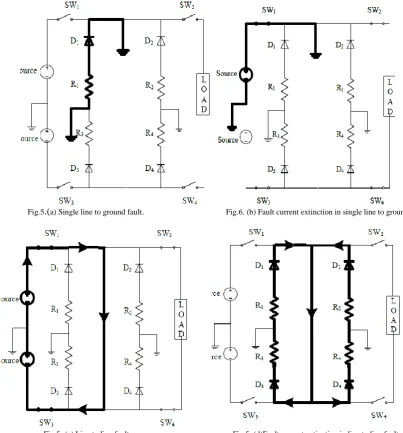
The proposed protection scheme is shown in Fig.4. This scheme isolates the faulty section from healthy system of DC microgrid in the event of fault. The other buses continue to provide supply power to load without interrupting the system so reliability of the system is increases. This results in maintaining the supply continuity to the load so system is stable. To achieve this, a closed loop type bus system is suggested. When the length of distribution system is not so long the closed loop type system has good efficiency [16].
In proposed scheme current sensor continuously senses and monitors the current from the two ends of line and provides information to the main controller of normal and abnormal conditions of the system. In normal operating condition the current at the incoming and outgoing ends of line is nearly same. The current at the incoming and outgoing ends is not same when the any abnormal condition is occurs on the bus or distribution line. Under this abnormal condition the current sensors provide information of fault to main controller and it will operates and gives command to the solid state C.B. such as IGBTs to open and isolate faulty section from healthy section of the system and maintaining supply power in normal part of the microgrid system.
Fig.4. Proposed controller system shows only one bus protection. The controller operates when two currents are not same
i
diff =i
1- i
2 (1)Where i1 is the incoming current and i2 is the outgoing current. Depending on main controller action, solid state
ISSN(Online): 2320-9801
ISSN (Print): 2320-9798
International Journal of Innovative Research in Computer
and Communication Engineering
(An ISO 3297: 2007 Certified Organization)
Vol. 3, Issue 7, July 2015
Fault current extinction depends on the resistance of freewheeling path. If the freewheeling path resistance is large, fault current can be extinguished quickly [6].
Fig.5.(a) Single line to ground fault. Fig.6. (b) Fault current extinction in single line to ground Fault.
Fig.5. (c) Line to line fault Fig.5. (d)Fault current extinction in line to line fault.
Fig. 5. Fault current path and its mitigation in proposed scheme.
ISSN(Online): 2320-9801
ISSN (Print): 2320-9798
International Journal of Innovative Research in Computer
and Communication Engineering
(An ISO 3297: 2007 Certified Organization)
Vol. 3, Issue 7, July 2015
CB then it will operate and open the faulty circuit from the healthy one and the fault current will flow through the freewheeling path it is shown in fig.5. (d).
VI. SIMULATION RESULTS
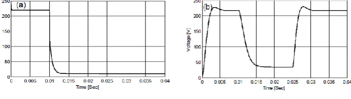
MATLAB-Simulation model for a bipolar DC bus with constant 240 V supply between two terminals is provided. The two sources are connected to feed a common load. A line to line fault is created in the middle of the bus 1. It is assumed that the controller will operate solid state C.B. means IGBTs in 0.025 second considering controller and switching solid state devices are faster in operation [5]. Simulation results are shown in Fig. 6 for line to line fault. Line parameters of system are given in Table 1.
Table 1: Parameters Of Line
Line Parameters Specifications
Load 10 KW
Freewheeling Resistance
50 Ώ
Line Resistance 121 Ώ mΏ /km
Line Capacitance 12.1 nF/km
Line Inductance 0.97mH/km
Bus Voltage 240 V
Bus Length 500 m
In table shows the values of the line parameters are used in the LVDC microgrid system in that gives the values of the load, freewheeling resisters and the line resistance, line capacitance and line inductance, bus voltage and the bus length of the system by this parameters we can make a MATLAB simulation model and obtain results of the LVDC bus microgrid system
Fig 6. (a) Load voltage without protection. Fig.6. (b) Load voltage with Protection.
ISSN(Online): 2320-9801
ISSN (Print): 2320-9798
International Journal of Innovative Research in Computer
and Communication Engineering
(An ISO 3297: 2007 Certified Organization)
Vol. 3, Issue 7, July 2015
Fig.6.(c) Load current without protection. Fig.6. (d) Load current with Protection.
Load Current without and with protection is shown in Fig. 6. When fault occurs on the LVDC bus microgrid system load current will be near about zero this will occur in case of without protection of the system after fault it is as shown in Fig. 6 (a), when the protection circuit is used in the LVDC bus microgrid system then the current will be restore quickly after the fault clearing it is shown in Fig. 6 (b) it is shown in fig. the fault is cleared within 0.025 sec it is very less time. So this increase the system reliability and continuity of supply.
Fig.7.Fault Bus Current Without Protection Fig. 8. Fault Path and Freewheeling Current
Fault bus Current without and with protection is shown in Fig. 7 and fig 9. When fault occurs on the LVDC bus microgrid system fault bus current will be very high this will occur in case of without protection of the system after fault it is as shown in Fig. 7, when the protection circuit is used in the LVDC bus microgrid system then the fault bus current will be restore or will get zero quickly after the fault clearing it is shown in Fig. 9 it is shown in fig. the fault is cleared within 0.025 to 0.03 sec it is very less time. So this is increase the system reliability and continuity of supply.
Fig. 9. Fault Bus current With Protection .
As the solid state switches such as IGBTs are opened fault current will be freewheeling through diodes and resisters and it will be get extinguished is as shown in Fig. 8. The fault current is shown in fig it will be freewheeling and grounded it within very less time in 0.025 to 0.03 sec. The protection devices in other buses are not shown here.
VII. CONCLUSION
ISSN(Online): 2320-9801
ISSN (Print): 2320-9798
International Journal of Innovative Research in Computer
and Communication Engineering
(An ISO 3297: 2007 Certified Organization)
Vol. 3, Issue 7, July 2015
section is extinguished through freewheeling diodes and resistance in the freewheeling path provided in the system. This provides additional protection to the system. This scheme is useful for the isolated area supplied through distributed generation and the system where the AC and DC microgrids are connected.
REFERENCES
1. R. Dugan, T. McDermott, “Distributed generation”, IEEE Ind. Appl. Mag., vol. 8, no. 2, pp 19-25, Mar./Apr. 2002.
2. R. Cuzner and G. Venkataramanan, “The status of DC micro-grid protection”, in Proc. IEEE Ind. Appl. Soc. Annu. Meeting, Oct.2008, pp. 1–8. 3. F. Blaabjerg, R. Teodorescu, M. Liserre, and A. Timbus, Overview of control and grid synchronization for distributed power generation
systems,‖ IEEE Trans. Ind. Electron., vol. 53,no. 5, pp. 1398–1407, Oct. 2006.
4. R. Lasseter and P. Paigi, “Microgrid: A conceptual solution”, in Proc. 35thAnnu. IEEE Power Electron. Specialists Conf., 2004.
5. J. Park, J. Candelaria, “Fault detection and isolation in low voltage DC-Bus microgrid system” IEEE Trans. Power Del., vol. 28, no. 2, pp. 779-787, Apr. 2013.
6. H. Nikkhajoei and R. Lasseter, “Distributed generation interface to the CERTS microgrid”, IEEE Trans. Power Del., vol. 24, no. 3, pp. 1598– 1608, Jul. 2009.
7. M. Saeedifard, M. Graovac, R. Dias, and R. Iravani, “DC power systems: Challenges and opportunities”, in Proc. IEEE Power Energy Soc.
Gen. Meeting, July 2010, pp.1–7.
8. Salomonsson, L. Soder, and A. Sannino, “Protection of low voltage DC microgrids”, IEEE Trans. Power Del., vol. 24, no. 3, pp. 1045–1053, Jul. 2009.
9. J. Candelaria and J.-D. Park, “VSC-HVDC system protection: A review of current methods”, in Proc. IEEE/Power Energy Soc. Power Syst.
Conf. Expo., Mar. 2011, pp. 17.
10. P. Salonen, P. Nuutinen, P. Peltoniemi, and J. Partanen, “LVDC distribution system protection: Solutions, implementation and measurements”,
in Proc. 13th Eur. Conf. Power Electron. Appl., 2009, pp. 1–10.
11. P. Cairoli, R. Dougal, U. Ghisla, and I. Kondratiev, “Power sequencing approach to fault isolation in dc systems: Influence of system parameters”,inProc. IEEE Energy Convers. Congr. Expo. 2010, pp. 72–78.
12. L. Tang and B. Ooi, “Locating and isolating DC faults in multi terminal DC systems”, IEEE Trans. Power Del., vol. 22, no. 3, pp. 1877–1884, Jul. 2007.
13. Y. Ito, Y. Zhongqing, and H. Akagi, “DC micro grid based distribution power generation system”, presented at the 4th Int. Conf. Power Electron. Motion Control, Xi‟an, China, Aug. 2004.
14. R. Schmerda, S. Krstic, E. Wellner, and A. Bendre, “IGCTs vs. IGBTs for circuit breakers in advanced ship electrical systems”, in Proc.
IEEEElectric Ship Technol. Symp., Apr. 2009, pp. 405.
15. J. Das and R. Osman, “Grounding of AC and DC low-voltage and medium-voltage drive systems”, IEEE Trans. Ind. Appl., vol. 34 no. 1, pp. 205–216, Jan./Feb. 1998.
16. M. Saisho, T. Ise, and K. Tsuji, “Configuration of DC loop type quality control center”, in Proc. Power Convers. Conf., 2002, vol. 2, pp. 434– 439.
BIOGRAPHY
Rote Sunil Kalyan is a Student, Dept.of Electrical Engineering, TSSM's B.S.COER Narhe, Pune, University of
Pune,Maharashtra, India.
Kulkarni J.S. is a Professor, Dept. of Electrical Engineering, TSSM's B.S.COER Narhe, Pune, University of Pune,