ABSTRACT
UÇAR, AHMET BURAK. Development & Characterization of Multifunctional Microfluidic Materials. (Under the direction of Dr. Orlin D. Velev.)
The field of microfluidics has been mostly investigated for miniaturized lab on a chip devices for analytical and clinical applications. However, there is an emerging class of “smart” microfluidic materials, combining microfluidics with soft polymers to yield new
functionalities. The best inspiration for such materials found in nature is skin, whose
functions are maintained and controlled by a vascular “microfluidic” network. We report here the development and characterization of a few new classes of microfluidic materials.
First, we introduced microfluidic materials that can change their stiffness on demand. These materials were based on an engineered microchannel network embedded into a matrix of polydimethylsiloxane (PDMS), whose channels were filled with a liquid photoresist (SU-8). The elastomer filled with the photoresist was initially soft. The materials were shaped into a desired geometry and then exposed to UV-light. Once photocured, the material preserved the defined shape and it could be bent, twisted or stretched with a very high recoverable strain. As soon as the external force was removed the material returned back to its pre-defined shape. Thus, the polymerized SU-8 acted as the ‘endoskeleton’ of the microfluidic network, which drastically increased the composite’s elastic and bending moduli.
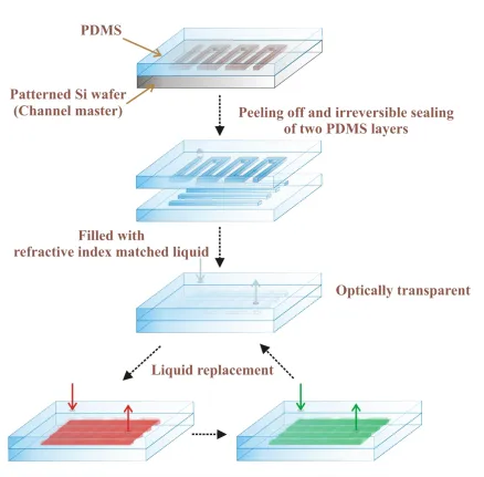
Second, we demonstrated a class of simple and versatile soft microfluidic materials that can be turned optically transparent or colored on demand. These materials were made in the form of flexible sheets containing a microchannel network embedded in PDMS, similar to the photocurable materials. However, this time the channels were filled with a glycerol-water mixture, whose refractive index was matched with that of the PDMS matrix. By pumping such dye solutions into the channel network and consecutively replacing the medium, we showed that we can control the material’s color and light transmittance in the
To better design new color changing elastomers, we investigated the role of the network geometry on liquid replacement efficiency with the aid of a multiphysics modeling and simulation software package, COMSOL. We simulated the liquid flow in various network geometries. Serpentine, parallel channel and lattice networks, as well as their tapered versions were compared. The comparison criteria were based on rapid and uniform liquid replacement with the least amount of dye/liquid required, for which we set multiple constraints such as constant inlet pressure or total channel area. We demonstrated that the tapered lattice type network provided the most rapid and uniform replacement with minimal
liquid waste.
Next, we designed a simple and inexpensive liquid dispensing microfluidic material which does not require complex micromachining techniques or automated actuators. It consisted of only a PDMS matrix with embedded chambers and channels. ‘Pores/slits’ were
made on the surface and the liquid was released by contact on the dispensing surface of the material. We varied the network design, geometry, dimension, slit shape and length, and tested the material’s liquid release performance. Promising preliminary results were obtained
but for an end product with repeatable and reproducible performance, both material fabrication and characterization need to be improved further.
Finally, we describe an alternative material/method for the fabrication of microfluidic materials. We aimed to replace the conventional fabrication material PDMS with Polyethylene (PE) sheets. The sheets were as transparent and flexible as PDMS, and also thinner. Channel patterns were drawn with a polymer solution of PolyVinylAlcohol (PVA), which is immiscible with PE, and captured in between the two PE sheets. After fusing the PE sheets on a hot press, PVA was washed off with water, so that the ‘microfluidic channels’
© Copyright 2013 by Ahmet Burak Uçar
Development & Characterization of Multifunctional Microfluidic Materials
by
Ahmet Burak Uçar
A dissertation submitted to the Graduate Faculty of North Carolina State University
in partial fulfillment of the requirements for the degree of
Doctor of Philosophy
Chemical Engineering
Raleigh, North Carolina
2013
APPROVED BY:
_______________________________ ______________________________ Sonia Grego Glenn M. Walker
_______________________________ _______________________________ Kirill Efimenko Michael Dickey
________________________________
DEDICATION
This dissertation is dedicated
to my sister, Banu,
to my parents, Hafize and Talip Uçar,
and in memory of my grandmother
BIOGRAPHY
Ahmet Burak Uçar was born in 1983 in the largest city of Turkey, in İstanbul, where continents meet. From ages eleven to nineteen he attended one of the top high schools in
Turkey, İstanbul Erkek Lisesi (İEL), in which mathematics and science classes were taught in German. After earning his Abitur degree from İEL, he passed the nation-wide university entrance test, and he won the right to study Chemical Engineering in Boğaziçi University
(BOUN), İstanbul. In 2006, during his senior year, he went to University of Oklahoma (OU), U.S.A., for one semester as an exchange student and then he decided to strengthen his academic career with a PhD degree. Right after finishing his Bachelor Degree in BOUN, he moved to Raleigh, NC, U.S.A. in Fall 2007 to pursue his PhD in the Department of Chemical and Biomolecular Engineering at North Carolina State University (NCSU). Since 2008 he has been performing his research studies under the guidance of Dr. Orlin D. Velev.
ACKNOWLEDGMENTS
I could not have accomplished this dissertation without the help and support of my family, friends and colleagues. However, with his wisdom, guidance and enthusiasm, my adviser Dr.
Orlin D. Velev has played the main role in this work. His positive and energetic personality has always kept me on track. He has been available for me all the time no matter how busy his schedule is. I am really lucky to have worked with him and to have been a part of Velev Research Group.
I would like to thank the members of my committee, Dr. Kirill Efimenko, Dr. Michael Dickey, Dr. Glenn Walker and Dr. Sonia Grego for their time and constructive feedbacks. I would like to acknowledge all the CBE faculty members and staff for their favors. Also I am grateful for the financial support of the CBE department and MeadWestvaco for this research.
Throughout my PhD years I have had great colleagues and friends. I would like to thank my fellow doctoral students—those who have moved on, those who are about to see the end, and those just beginning—for their support, feedback, and friendship. Suk Tai introduced me microfluidics and I learned from him a lot. I have enjoyed my time spent with Vinayak who has been a great friend and support. For color changing elastomers I thank Sumit for his contributions. I would like to thank each, Stoyan, Lindsay, Sejong, Liz, Jairus, Etienne, Elena, Daniel, Alex, Tian, Yan, Shan, Naren, Rachita, Selver, Anne-Laure, Bhuvnesh, Stephanie and Brittany for their assistance, discussions and friendship. It has been great fun to pass these years with my class and sports teammates Hyung Jun, Jess and Casey
who has been also a close friend since the very first day of NCSU. Also I would like to thank all other friends, especially Namık, for these memorable times in North Carolina State
University.
Last, but certainly not least, there are no words to describe my appreciation for my family’s motivation and support. They have been the largest contributing factor to my
TABLE OF CONTENTS
LIST OF TABLES ... vii
LIST OF FIGURES ... viii
CHAPTER 1 ... 1
Introduction to Microfluidics... 1
1.1 Introduction – History of Microfluidics ... 2
1.2 Microfluidic Device Fabrication ... 8
1.3 Characteristics of the Fluid Flow at the Micro-Scale ... 13
1.4 A New Class of Soft Microfluidic Materials ... 19
1.4.1 Materials of Controlled Shape and Stiffness with Photocurable Microfluidic Endoskeleton ... 23
1.5 Goals and Layout of This Dissertation ... 28
1.6 References ... 29
CHAPTER 2 ... 36
Microfluidic Elastomer Composites with Switchable Vis-IR Transmittance ... 36
2.1 Introduction ... 37
2.2 Fabrication and Operation... 37
2.2.1 Fabrication ... 37
2.2.2 Fluids and Operation ... 41
2.3 Results and Discussion ... 41
2.4 Conclusion and Potential Applications ... 49
2.5 Acknowledgements ... 51
2.6 References ... 52
CHAPTER 3 ... 56
Analyzing the Role of Network Geometry on the Fluid Displacement Efficiency in Microfluidic Color Changing Windows ... 56
3.1 Introduction ... 57
3.2 Design ... 58
3.3 Simulation Results and Analysis ... 62
3.4 Conclusion ... 74
3.5 References ... 75
CHAPTER 4 ... 78
On-Contact Liquid Dispensing Microfluidic Material ... 78
4.1 Introduction ... 79
4.2 Material Fabrication, Design Parameters and Operation ... 81
4.3 Results and Analysis ... 86
4.5 References ... 92
CHAPTER 5 ... 95
An Alternative Material and Method for Fabrication of Simple and Inexpensive Microfluidic Materials ... 95
5.1 Introduction ... 96
5.2 Proposed Mechanism and Materials ... 97
5.3 Results and Discussion ... 98
5.4 Conclusion and Future Modifications ... 101
5.5 References ... 102
CHAPTER 6 ... 104
Summary and Future Outlook ... 104
6.1 Summary ... 105
6.2 Future Outlook ... 107
APPENDIX ... 110
LIST OF TABLES
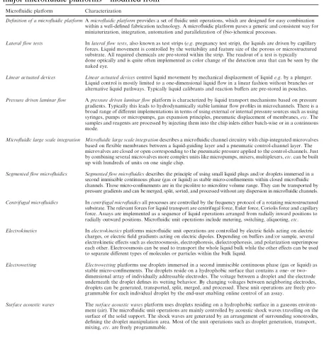
Table 1.1 A definition of a microfluidic platform in general and short characterizations of major microfluidic platforms – modified from39 ... 6
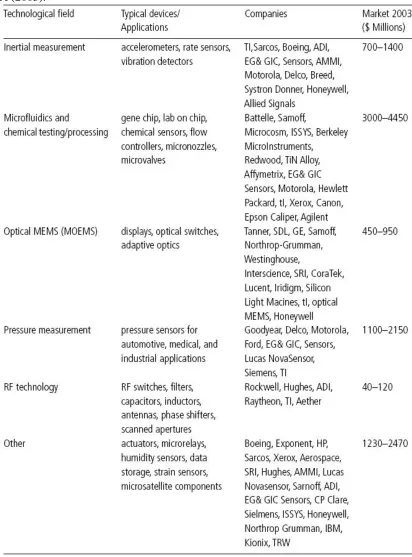
Table 1.2 Examples of companies involved with MEMS and microfluidics technology in USA (2003).1 ... 7
Table 1.3 A list of the dimensionless numbers commonly used in micro-scale fluidic systems and their significance. ... 15
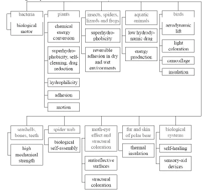
Table 1.4 An overview of various systems and objects from nature and their selected functions being analyzed for biomimetic materials – modified from59. ... 19
Table 3.1 Simulation parameters, fluid properties and constraints. ... 60 Table 4.1 List of the major fabrication and design parameters of liquid dispensing
prototypes ... 84
LIST OF FIGURES
Figure 1.1 Size characteristics of microfluidic devices in length and volume scale2: a mm sized “microfluidic” system could process a liquid volume of μL. Most of the microsystems deal with liquid volumes of nL. ... 3
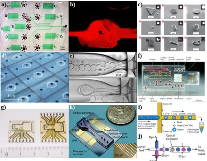
Figure 1.2 Examples of low cost and innovative microfluidic devices: (a) a diagnostic device performing sandwich immunoassays3, (b) microfluidic mixing with the help of embedded diodes41, (c) shape controlled polymer micro-particles obtained from the UV-photo induced polymerization of multiphase laminar flows within a microchannel34, (d) a photograph of a mass-producible device to diagnose infectious diseases28, (e) monodisperse double emulsions generated in a micro-capillary device42, (f) an image of a disposable diagnostic card27, (g) a microfluidic cytological tool for cell counting and separation, consisting of an integrated micro-fabricated chip with an elastomer cover and molded fluidic connections43, (h) an optical image of a device for particle separation in a microfluidic channel via standing surface acoustic waves33, (i) a schematic of single cell or single-copy genetic analysis (SCGA) in nanoliter droplets. Beads pumped through a micro-fabricated droplet generator30, (j) a schematic diagram of a microfluidic droplet dye laser37. ... 4
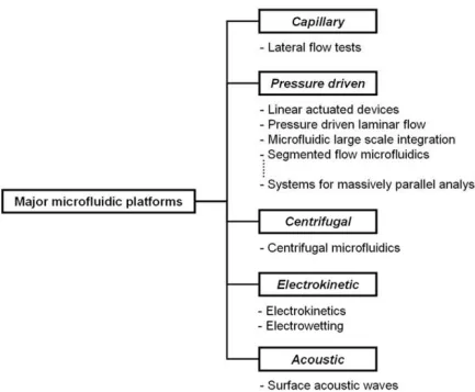
Figure 1.3 Microfluidic platforms classified according to their actuation method.40 They are described in detail in Table 1.1. ... 5
Figure 1.4 An example to omnidirectional printing of a 3-D microvascular network within a hydrogel reservoir, (a) the ink is in a chemically cross-linked hydrogel matrix, (b) the ink is liquefied and removed to expose the microvascular channels - modified from46. ... 9
Figure 1.5 Broad categories of micro-fabrication processes. The techniques are grouped according to their fundamental commonalities, whereas there are also other classification alternatives in terms of material, serial versus parallel approaches, overall dimensional scale etc. Some of the most commonly encountered bulk modification processes in micro-fabrication which are not listed here include ion implantation, diffusion, and annealing.44... 9
capacity (J kg-1 K-1) of selected materials - modified from44. ... 11
Figure 1.7 Schematics of typical sequences of steps in microfluidic device fabrication11,51: (a) detailed process flow for creating PDMS microfluidics using SU-8 molds51, (b) a brief 3-D illustration of the process11, a transparency carries the desired design, which is transferred to the photoresist on the Si wafer by photolithography. Many PDMS replicas can be fabricated by molding, and they can be sealed onto various surfaces reversibly or irreversibly depending on the need. Surfaces can be treated chemically before the seal to ease the aqueous flow. ... 12
Figure 1.8 Some fundamental size scales relevant to fluid physics depending on the length scales. As it moves from macro to micro and further to nano, the assumptions for relevant governing equations and boundary conditions change.54... 14
Figure 1.9 Velocity profile for the pressure driven flow11: (a) A pressure gradient generates a parabolic velocity profile, schematic representation, and (b) experimental observation of the fluid in Poiseuille flow with the help of fluorescence. ... 18
Figure 1.10 Examples of novel microfluidic materials: (a) autonomic crack repair by microencapsulated healing agent embedded in the system58, (b) schematic diagram and an optical image of a self-healing structure after crack formation62, (c) an elastic adhesive is embedded in the microchannels57, (d) photographs of a metallic microstructure with a basket-weave pattern embedded in PDMS65, (e-f) pigment dispersions of a microfluidic leaf64, (g) an x-shaped soft robot in five different regions adopting coloration for background matching64. ... 20
Figure 1.11 Examples of various organs on chips: (a) artificial liver cell, a photo of the final cell-patterning chip and the SEM image of the detail electrode geometry. The close-view shows the concentric ring electrodes with stellate-tips70, (b) lung on a chip, a photo showing blood and air inlets and outlets and the microfluidic channels comprising the device69, (c) PDMS cilia, optical images of cilia in air71, (d) and collapsed PDMS cilia due to water introduction, scale bars: 200 µm71. ... 21
arterial-like 3D flow network path for two input nodes determined by gradient-based optimization. ... 22
Figure 1.13 Schematics of the fabrication of photocurable microfluidic endoskeleton structure by filling epoxy-based SU-8 photopolymer into microfluidic channel networks. During UV exposure, the SU-8 photoresist within the deformed channel network is solidified, and the preprogrammed deformation of the photocured channel network is retained, even after the external force is removed. ... 24
Figure 1.14 Photographs and schematic of PDMS sheets with embedded photocurable microfluidic endoskeleton. (a) a soft and stretchable silicone sheet filled with liquid SU-8 photopolymer before UV exposure. After deforming the sheets and exposing to UV light for 15 min, the photocured microfluidic composites with solidified SU-8 photoresist retain the defined shapes, such as (b) wave, (c) spiral, and (d) saddle. The microchannels embedded in PDMS layers were 450 µm thick in (a) and (d), 165 µm thick in (b), and 275 µm thick in (c). (e) Orthogonally oriented microchannel structure embedded within PDMS matrix. The channel width and interchannel distance were 400 and 250 µm, respectively. The channel thickness was varied from 150 to 450 µm. The microfluidic network had an overall length of 36 mm and a width of 24 mm. The channels in the schematic are not to scale. ... 25
Figure 1.15 (a) Elastic modulus of PDMS-only layer and photocurable microfluidic networks before and after UV exposure as a function of volume fraction of SU-8 photoresist in PDMS matrix. The solid lines are least square fits. The dot-dash line is based on the estimated values, (b) Bending modulus of PDMS-only layer and photocurable microfluidic networks after UV exposure as a function of the volume fraction of photoresist in the matrix. ... 26
Figure 2.1 Schematic flowchart of the fabrication and operation principle of the PDMS microfluidic material network that can change color on demand. The glycerol–water mixture matches the refractive index of PDMS and makes the channels optically transparent. The liquid in the channels can be replaced with dye solutions to change the transmittance spectra of the material. ... 38
Figure 2.3 Channel structure of the color changing elastomeric sheets: (a) a sample with a typical double-channel network, also illustrating a color change from red to blue, (b) side view schematic, (c) an image of the flexible microfluidic network filled with Allura Red dye solution, (d) magnified view of the same material illustrating the double-channel network design. The channels are sealed onto each other orthogonally. ... 40
Figure 2.4 Refractive indexes of glycerol-water mixtures. The refractive index increases linearly with increasing glycerol mass fraction in the mixture, whereas the change in the viscosity of the mixture was non-linear. A 61% glycerol-water mixture with a viscosity of ~0.01 Pa s matched the PDMS network’s refractive index. ... 42
Figure 2.5 Digital photographs and absorbance spectra of the microfluidic network: (a) absorbance spectra of empty and liquid-filled PDMS microfluidic networks. The presence of refractive index matched glycerol–water mixture in the channels results in better transmittance of the network, (b) an air-filled, double-channel PDMS network positioned on top of a yellow paper background and (c) the same double-channel network filled with refractive-index matched liquid mixture allows observation of the background texture. ... 43
Figure 2.6 Digital photographs of the single-channel PDMS network material filled with: (a) air, (b) 61 wt% glycerol–water mixture to make the channels visually transparent, and (c–e) Brilliant Green, Allura Red and Bromophenol Blue solutions in the refractive index matched liquid. The image in the inset illustrates a snapshot taken during the color change from green to red, (f) at the end, a clear 61 wt% glycerol–water mixture is pumped back into the channels. Note that replacement took place without mixing due to the laminar flow in channels and one solution replaced another thoroughly in 13 seconds. ... 44
Figure 2.7 Absorbance spectra of Allura Red, Bromophenol Blue, Brilliant Green, and N-IR dye solutions in 61 wt% glycerol-water mixture measured in cuvette with a 10 mm path length. ... 46
modified eqn (2.2) on the basis of the experimental spectra of each component in the material. ... 47
Figure 2.9 Absorbance spectra for dilute Allura Red solutions of different concentrations measured in cuvettes. Based on the most dilute concentration, which was 0.00085 wt.% Allura Red in 61 wt.% Glycerol-Water mixture, each spectrum was calculated by using linear relation of A with C. Straight lines correspond to the original spectra and the dashed/dotted ones are the ones obtained through scaling. The more concentrated the solution became the higher was the deviation between the experimental and theoretical spectra. We believe that this deviation is the main reason for the difference in Fig. 2.8b as the concentration used in the channels is ~10 times higher than the most concentrated solution in the Fig. 2.9. ... 48
Figure 2.10 (a) Vision of energy-efficient residential home or office building using microfluidic materials for control of radiation and convection heat flows, and (b) schematic of the heat exchange in the wall network. The material can be placed on back wall to exchange heat using underground well water or solar heated water. Colored liquid can be pumped through the channels of the material to change the wall color on demand. Material placed on window can become transparent or opaque in the IR and visible light regions on demand or absorb/transmit near-infrared solar radiation. ... 51
Figure 3.2 Liquid replacement and distributions in S- vs. H-shape networks with varying channel sizes. Their liquid displacement rates at 10 s are shown here. 19-channel-networks are illustrated in a-c. (a) S-network (939 µm wide channels) with 1 kPa inlet pressure, (b) H-network (930 µm wide channels) with 1 kPa inlet pressure, (c) S-network (939 µm wide channels) with 30 kPa inlet pressure, (d) Red liquid’s average concentrations in the whole network are plotted for all S- and H-networks (Maximum concentration they could reach is 1.0 mol m-3). At the same inlet pressure H-networks are superior to S-networks in terms of liquid displacement rate, whereas they could not provide a uniform displacement in this single-scale form. Decreasing individual channel sizes slowed down displacement efficiency significantly due to lower flow rates. ... 62
Figure 3.3 Fluid replacement data for H-networks with constant channel size but varying total surface area (the only case where we relaxed our constant total area constraint) vs. S-19 network. Inlet pressures are 30 kPa. Channel widths are 936 µm +/- 6 µm. Ratios of the network length to width were kept constant in all expansions, since same surface area with different aspect ratios exhibited different coverage performances. Total area expansion factors are shown in the legend, whereas numbers in parentheses refer to the width & height expansion ratio.. ... 64
Figure 3.4 Liquid displacement in H-networks with different channel sizes. The images correspond to the instants when displacing liquid in each network reached to an average concentration of ~0.3 mol m-3 in Fig. 2d (i.e. ~30% displacement efficiency) and illustrate individual network’s flow non-uniformity: (a) 19-channel-H-network (930 µm) at 5.7 s, (b) H-25 (710 µm) at 7.4 s, (c) H-37 (482 µm) at 11.6 s, (d) H-51 (351 µm) at 18.7 s. As we decrease the channel size, flow uniformity decreases and more time is required to displace the same amount of liquid. However, to keep the channels optically indistinguishable from each other, we aimed to modify the H-51 network geometry so that even the displacement in narrow channels could be done without compromise of speed and uniformity... 64
correspond to the same area with a constant width ratio 1.83:1 as in a, (c) constant width D/C: 4:1, (d) tapered D/C: 7:1, equivalent to constant width D/C: 4:1 as in c, (e) tapered D/C: 11:1, equivalent to constant width D/C: 6:1, (f) liquid displacement performances of H-51 networks with tapered and/or only wide D/Cs. The larger average width of D/Cs enables better flow access of the network. However, tapering the D/Cs improves the networks’ performance more significantly than simply using wide D/Cs. ... 66
Figure 3.6 Snapshots of two H-51 networks with 50% average concentrations: (a) tapered and wider D/C: 5.5:2.5, equivalent to a constant width D/C with 4:1 ratio as in Fig. 3.5c and d, (b) tapered and wider D/C: 8:2, equivalent to a constant width D/C with 5:1 ratio. ... 68
Figure 3.7 Comparison of material (liquid) use efficiencies of the networks with tapered and wide D/Cs. Networks with only wide (non-tapered) D/Cs waste more liquid. High tapering ratios seem to be in favor of efficient liquid, although a combination of both wide and tapered D/Cs’ performance is also notable especially when we take into account the time variable... 69
Figure 3.8 Simulations of liquid replacement in lattice network: Horizontal and crossing channels have the same size whereas D/Cs were wider and/or tapered: (a) Snapshot of the network with D/C tapering ratio of 4:1 when 90% of the original liquid in the channels were displaced with the colored one, (b) liquid displacement rates of the lattice networks with different D/Cs, (c) liquid use efficiencies of the corresponding lattice networks for 90% displacement. As tapering ratio of D/Cs increased, not only displacement time but also waste of colored liquid decreased. Compared to H-networks, lattice networks with less tapering provided a more rapid and uniform flow with less liquid waste... 70
90% of the liquid with less than ~5% waste of colored liquid in less than 11 seconds. ... 72
Figure 3.10 Comparison of various networks simulated in this study. Images refer to the times required for 30% liquid displacement, which was chosen to illustrate flow uniformity performances of the networks. Except S-25, all the inlet pressures are 1 kPa and channel sizes range from 343 µm to 351µm: (a) S-25 with an inlet pressure of 30 kPa. S-51 network could not displace 30% in the simulation times, thus we included here S-25 just to represent the flow uniformity of S-networks, (b) single-scale H-51 network had a non-uniform flow (inverse-parabolic) in the network, (c) 51 network with wider D/Cs, 4:4, flow line became flatter, (d) H-51 network with tapered D/Cs, 11:1, provides a ‘vertically’ uniform flow, (e) lattice network with single tapering ratio 4:1, (f) lattice network with double tapering ratios 4:2 & 7:2, provides a ‘diagonally’ uniform flow. ... 73
Figure 4.1 Schematic of the concept of a new liquid dispensing device: when a force is applied on the top surface of the PDMS layer, liquid in the channels will be delivered to the surface through the openings/slits and will be later replenished from the internal reservoir. ... 81
Figure 4.2 (a) A digital photograph of an empty prototype where the chambers are placed on top of the channel network and (b) a schematic of it filled with a red liquid. Slits connect the chambers to the surface. ... 82
Figure 4.3 Photomask examples of the network geometries tested in the initial stage of the network design selection. In addition to size variations, the design parameters evaluated included chambers shape (square vs. circular), placement (top vs. bottom layer), channel placement (on single vs. both layers) and connections (parallel vs. web) ... 83
Figure 4.4 Schematic of liquid release for the design where the material consists of a microfluidic network and capillary pores opening to the surface due to the pressure applied on the surface. Once the liquid is released, it is replenished. ... 85
Figure 4.5 Schematic of the configuration where chambers serve as local reservoirs and the slits are cut in the channels. Once pressure is applied on the top surface, the liquid in the chamber is released through the slit. ... 87
surfactant on the liquid filling/flow, digital images on the left illustrate the networks without surfactant whereas the ones on the right contains liquid with surfactant. The networks illustrated here show the following samples: (a) a parallel channel network without surfactant, (b) a serpentine network with surfactant, (c) and (e) networks with physical obstacles without surfactant, (d) and (f) networks with physical obstacles with surfactant. Chambers in (b) are fully filled vs. only partially filled in (a) (positive effect of the surfactant). However we also had several cases where chambers were either not fully filled or had bubbles, (such as (c) & (e) vs. (d) & (f)), although the liquid contained surfactant. We believe here networks’ geometries play a more important role than the surfactant, such as the web formation of the channels in (c) and/or focused flow due to obstacle enabling a smoother filling (e). In some networks, we observed bubbles in the system - possibly due to surfactant (f), although they were sometimes present in networks without surfactant (e). Independently of network designs, occasionally we had dead regions during filling or after release, such as in (b) and (c), because of defects during the master fabrication or because of irreversible sealing. ... 88
Figure 4.7 Overview of the liquid release testing procedure: (a) a filter paper is placed between the solid tip and PDMS device to absorb the released liquid, (b) on a separate run, to have a clear observation of the fluid flow during the pressing under microscope, a filter paper is cut in the shape of the tip and material is pressed on the tip by hand, (c) side view of the PDMS material placed on a scale before being pressed against the fixed solid tip, (d) an image of a filter paper, which absorbed the dispensed liquid at five different spots. ... 89
Figure 4.8 Quantification of the dispensed liquid through individual slits. This is an example set of data illustrating the homogeneous release capacity of the materials. Each sample could have maximum of 5 data points representing the release through its five slits. Some of the samples dispensed constant amount of liquid independent of the weight put on the surface (such as S25 or S17), whereas in some samples each slit released different amount of liquid even with the similar force applied (such as S07 or S11). ... 91
Figure 5.2 Two sample images of PE sheets with PVA drawn on them (during drying stage). The sheets had an area of ~8 x 10 cm: (a) different colors represent different concentrations of PVA. The lines have a width of ~0.9-1.0 mm, and were drawn with a pipette tip, (b) the lines had a width of ~0.8 mm and drawn via an ink pen filled with PVA solution. They were sealed with an empty PE sheet after 3-4 hours of drying. ... 99
CHAPTER 1
1.1 Introduction – History of Microfluidics
In a speech delivered in 1959, Richard P. Feynman noted that “There is plenty of room at the bottom”, inspiring the modern research motif in micro- and nanotechnologies.1,2
Constructing and employing microscopic mechanical and electronic devices has been a growing trend since then. New disciplines in engineering emerged as the advances in electronics spawned a new field in the 1980s - microelectro-mechanical systems (MEMS).
MEMS, whose total size varies roughly between 1 and 300 µm, had primarily been created to replace traditional methods for challenging observations and measurements, such as the measurement of fluid-phase chemical kinetics, and the characterization of the boundary slip phenomenon in gases. Important industrial successes, such as use of these systems in airbag activation also increased the interest in MEMS. Integration of detection, information analysis, and signal processing on one chip led to success, which created an increased demand for MEMS by numerous industries.1
With time, MEMS devices have found more and more applications in chemical
engineering, biology and biomedicine. In the 1990s, the convergence of micro-devices and fluid flow led to the establishment of another new discipline – microfluidics. With its fluidic focus, the field has enabled the development of micro-sensors, pumps, valves and as well as a myriad of lab-on-a-chip devices.1-3
Figure 1.1 Size characteristics of microfluidic devices in length and volume scale2: a mm sized “microfluidic” system could process a liquid volume of μL. Most of the microsystems deal with liquid volumes of nL.
Scaling down to the micro scale has not only led to various types of micro-pumps, mixers, valves, and separators, but also to many complex fluid handling devices since the 1990s. These devices can control gas and liquids4,10,24, measure temperature25,26, perform medical testing19,27,28, DNA analysis29,30, cell sorting15,31, separation-based detection32,33, micro-particle/structure synthesis14,17,34,35, integration with advanced optical devices36-38 and
much more (Fig. 1.2). These devices include miniaturized labs on a chip and processes which are also called micro-total analysis systems (μTAS).1-3,5,7,11,18,21 Relative to the
Figure 1.2 Examples of low cost and innovative microfluidic devices: (a) a diagnostic device performing sandwich immunoassays3, (b) microfluidic mixing with the help of embedded diodes41, (c) shape controlled polymer micro-particles obtained from the UV-photo induced polymerization of multiphase laminar flows within a microchannel34, (d) a photograph of a mass-producible device to diagnose infectious diseases28, (e) monodisperse double emulsions generated in a micro-capillary device42, (f) an image of a disposable diagnostic card27, (g) a microfluidic cytological tool for cell counting and separation, consisting of an integrated micro-fabricated chip with an elastomer cover and molded fluidic connections43, (h) an optical image of a device for particle separation in a microfluidic channel via standing surface acoustic waves33, (i) a schematic of single cell or single-copy genetic analysis (SCGA) in nanoliter droplets. Beads pumped through a micro-fabricated droplet generator30, (j) a schematic diagram of a microfluidic droplet dye laser37.
In terms of the driving force of the systems, the integrated microfluidic devices/platforms consisting of different ‘unit operations’ can be categorized in five groups:
Figure 1.3 Microfluidic platforms classified according to their actuation method.40 They are described in detail in Table 1.1.
provides an overview to the developments in MEMS and microfluidics industry. Due to its novelty, convenience, and potential, microfluidic research is now a part of many engineering programs and every day new devices pushing current limits are being fabricated.1-3,7
1.2 Microfluidic Device Fabrication
Most of the instrumental processes used to fabricate MEMS are utilized in the manufacture of microfluidic devices as well.In terms of structure, most microfluidic devices tend to be far less complex than microelectronic circuits. However, not being entirely solid-state, having moving parts and containing fluid media, makes microfluidic devices in a sense more complicated than microelectronic devices. Batch fabrication of devices is possible with many replication and forming techniques such as traditional silicon-based micromachining technologies, which can provide the masters for replication. Complex microfluidic devices based on plastic microfabrication could be fabricated in the near future with further achievements of plastic-based microelectronics.44
The selection of the fabrication method principally depends on the desired function of device, and which substances will be used in the channels. For instance, microfluidic devices fabricated in materials such as stainless steel or ceramics are desired for applications featuring highly corrosive chemicals. Micro-cutting, laser machining, micro-electro
machining, and laminating are a few examples of alternative fabrication techniques. Another novel alternative is ‘cofabrication’, which represents a new model for designing and building multicomponent microsystems. It facilitates precise integration and registration of multiple materials in one layer enabling simple and economical fabrication.45 These alternatives offer some advantages in structure flexibility. For instance, by using different modifications of the direct ink writing technique, 3-D microvascular structures (Fig. 1.4) could be fabricated.46 The freedom of material choice make these techniques serious competitors for silicon micromachining, since the necessary geometric features of the device is strictly determined by the choice of the material, which creates limitations for the device use in terms of both application and commercial aspects.2,44
Figure 1.4 An example to omnidirectional printing of a 3-D microvascular network within a hydrogel reservoir, (a) the ink is in a chemically cross-linked hydrogel matrix, (b) the ink is liquefied and removed to expose the microvascular channels - modified from46.
techniques, whereas for polymer microfabrication12 there are many different methods
depending on the requirements. High-pressure injection and hot embossing are two techniques that can be applied to plastics for making the devices appropriate for electrokinetic flow. Room temperature imprinting reduces the fabrication time (as low as 2 minutes), and injection molding enables the creation of 3-D shapes. Another method, the laser photoablation process, increases the electroosmotic mobility surface charge in the channels, but channel walls have greater surface roughness compared to the methods mentioned above.47 Some of the most commonly used fabrication techniques are listed in Fig 1.5.44
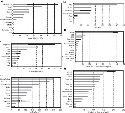
The materials used in the fabrication of the micro devices vary depending on the application. The purpose of these devices and the chemicals used in them are important criteria when choosing which material to use, as they have quite diverse mechanical properties (Fig. 1.6). The commonly used materials for the matrix of microfluidic devices may be divided into the major categories of polymers, silicon, glass, and metals. Originally, silicon and glass were the main materials for electrical and mechanical devices.47 Nowadays many polymers12 in the form of plastics and elastomers, such as polydimethylsiloxane (PDMS)3 – are used for microfluidic device fabrications. The biggest advantage of these “soft” materials is that they provide easy, rapid and inexpensive fabrication. While glass is
optically opaque to UV, plastics and polymers, such as PDMS, are optically transparent to both UV and IR, which can be useful in detection. They also allow a wider range of geometries to be fabricated. Probably due to these conveniences, PDMS is the most widely investigated polymer material in microfluidics. It belongs to the broader polymer class of silicones, which are characterized by a siloxane backbone of silicon and oxygen atoms.44 A single design master is enough to replicate several prototypes made of PDMS, and they can be sealed to other samples and surfaces reversibly or irreversibly.3,13,47 Furthermore, PDMS offers many advantages such as biocompatibility, thermal stability, chemical inertness, and low toxicity. As a result it has become one of the most used materials for the microfluidic devices.2,15 Some disadvantages of PDMS are its gas permeability and swelling in solvents, which makes it less favorable for some applications. However, some additives and fabrication modifications48 have been shown to be effective in reducing swelling.44
SU-8, which is an epoxy-based photocurable resin, is another common polymer that has gained widespread use in microfabrication particularly because of the high feature aspect ratio that can be achieved. It is subject to photocuring when exposed to UV radiation, while masked regions remain soluble and are removed during the developing step of photolithography. SU-8 is a versatile material for fabrication of extremely diverse types of
microfluidic devices. As a photosensitive yet mechanically resilient material, SU-8 is used for direct fabrication of microchannels and embedded flexible structures, as well as for
Figure 1.6 Mechanical and thermal properties of some common materials involved in microfabrication44: (a) Young’s modulus (GPa), (b) elongation (%), (c) tensile strength (MPa), (e) melting point (°C) and (f) specific heat capacity (J kg-1 K-1) of selected materials - modified from44.
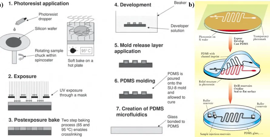
Taking into account the simplicity, soft lithography is the most common fabrication technique for the prototyping of microfluidic devices made of PDMS.3,6,11-13,49,50 Microfluidic devices can be fabricated by soft lithography in less than one day (Fig. 1.7), and the replicas are prepared much faster.13 In this technique, PDMS is the preferred elastomeric material. The designed channels are formed on a silicon wafer using a photoresist, SU-8, which is
achieved. The photoresist is spin coated on the wafer and then soft baked at 65°C and 95°C as required. A photomask is placed on top of the soft-baked photoresist and the wafer is exposed to UV light, so that the design on the photomask is transferred to the photoresist. After the master is post baked, the unpolymerized part of the photoresist is removed with the solvent, and the replica master can be used several times. The channel width can range from several to hundreds of microns.
Figure 1.7 Schematics of typical sequences of steps in microfluidic device fabrication11,51: (a) detailed process flow for creating PDMS microfluidics using SU-8 molds51, (b) a brief 3-D illustration of the process11, a transparency carries the desired design, which is transferred to the photoresist on the Si wafer by photolithography. Many PDMS replicas can be fabricated by molding, and they can be sealed onto various surfaces reversibly or irreversibly depending on the need. Surfaces can be treated chemically before the seal to ease the aqueous flow.
removed from the master by peeling it off carefully, after which holes (inlet, outlet etc.) are punched into the sample by a steel rod or a needle. The fabricated PDMS layers can be sealed on another PDMS layer, glass or another substrate reversibly. If an irreversible seal is desired, it should be treated with oxygen plasma and sealed immediately, as the oxidation effect wears off exponentially with time. To increase the strength of the irreversible seal, the PDMS layers can be cleaned with ethanol before plasma treatment, and after the seal, it can be cured in the oven at 70°C.2,3,11-13,44,47,49-51
1.3 Characteristics of the Fluid Flow at the Micro-Scale
Flow characteristics in microfluidic channels play an important role in the design of the devices. Kinematic, transport, thermodynamic and other properties of the fluid and/or flow, such as velocity, viscosity, diffusivity, pressure, temperature, surface tension, etc., determine how the fluid flow can be modeled or analyzed.2 Fluid flow analysis can be performed in two ways: as a continuum or as interactions of individual molecules.2,52,53 As the length scale
decreases (Fig. 1.8), it can be difficult to choose the better approach and relevant governing equations when analyzing the system, since the wall-surface interactions at a molecular scale may become important.53 However, if the molecules of a fluid are closely packed relative to the length scale of the flow, it can be safely modeled as a continuous medium. For instance, in a 10-μm channel, there would be ~30,000 water molecules, which is significant enough to select the continuum approach, and Navier-Stokes equations for the macro-scale still hold.2,52,53
Figure 1.8 Some fundamental size scales relevant to fluid physics depending on the length scales. As it moves from macro to micro and further to nano, the assumptions for relevant governing equations and boundary conditions change.54
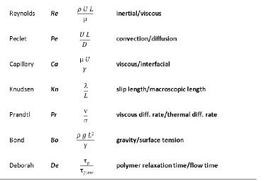
Analysis of fluid mechanics often benefits from dimensionless numbers that describe flow behavior by comparing active forces in the system. A summary of the commonly used dimensionless numbers and the ratios they represent is listed in Table 1.3. In microfluidics the most frequently mentioned dimensionless number is the Reynolds number (Re)1,8,55, which gives the ratio of inertial forces to the viscous forces:
Re
(1.1)
U L
where ρ is the density, U is the velocity, L is the characteristic linear dimension/diameter of
it takes relatively powerful actuators and pumps to drive a microfluidic device. In order to have such pumps/actuators/valves as integral parts of the microfluidic device, fabrication challenges had to be overcome. However, when Re is less than ~1, instead of integrating mechanical actuators with moving parts, surface-modulated phenomena could be used, such as electrokinetic pumping (e.g., electro-osmosis) and capillary surface-tension effects, electro-magnetic force fields, and acoustic streaming.53
Due to very low Re values, the flow regime in microfluidic systems can be safely classified as laminar. Exceptions to this rule could occur due to effects related to entrance
regions, non-Newtonian fluids, wall slip, surface roughness, and viscous dissipation44. Laminar flow could be both advantageous and disadvantageous depending on the application of the system. For instance, the laminar regime facilitates modeling and characterization of
the flow in the channels. On the other hand, mixing becomes a big problem since different liquid layers do not mix due to lack of turbulence. The only mixing in such devices is through diffusion, which is not rapid enough.8 That is why when comparing microfluidic flows to macro-scale counterparts, diffusion always plays a more important role compared to convection and bulk flow. Passive diffusion is mostly inadequate for rapid mixing applications and must be enhanced by certain methods, such as modifying channel walls to more actively disrupt flow streams.44 Especially for separation and filtering applications, a large diffusion coefficient can be beneficial. In these systems, the differences in diffusion
coefficient alone can be used to separate smaller particles from larger ones in a mixed flow without any need for membranes or centrifuge methods. Turbulent regimes can provide a solution for effective mixing, but it generally requires high flow rates, i.e. mostly high pressures and this could cause mechanical problems for microfluidic devices.1,2,11,44,55 On the other hand, for certain applications, inertial effects can be incorporated in microfluidic systems by changing geometry and increasing flow speed. Thus, for instance, enhanced mixing, particle focusing and separation could be achieved efficiently.56
The fluid flow in microfluidic devices can be generated by many external driving forces such as pressure gradients, capillary effects, electric and magnetic fields. Despite the physical variety, we can categorize them in two main driving forces, either by pressure (Poiseuille flow) or by electric field (electroosmosis or dielectrophoresis).7,11 Poiseuille’s law describes the flow of a Newtonian fluid through a circular tube of length L and radius r, and relates the flow rate Q to the pressure drop Δp across the conduit44,54
:
4
Q (1.2) 8 r p L
Another important parameter for characterizing microfluidic flow is the fluidic resistance, R. Fluidic resistance in a conduit is the pressure drop divided by the volume flow
channel varies proportionally to the inverse of the fourth power of channel radius44. This represents a very unfavorable scaling relationship for pressure-driven flow, because reducing a channel size by a factor of 10 increases the fluidic resistance by a factor of 10,000.
R 8 4L (1.3) r
The velocity profile observed for pressure driven flow is parabolic (Fig. 1.9) whereas it is mostly flat across the channel during the electroosmotic flow. In both flow types there are some disadvantages: first, in Poiseuille flow, the non-uniform flow speed makes some microfluidic devices impractical. For instance, separating different molecules in a solution would be more difficult with a parabolic flow profile since it broadens the bands of different species.11 Secondly, they require reliable mechanical pumps which are difficult to fabricate. On the other hand, the devices using electroosmotic pumping are highly sensitive to impurities in the fluid, which decreases the performance. These devices also need high voltage as the driving parameter.11 Nonetheless, these problems can be ameliorated by
manipulating the design parameters such as channel cross section, curvature, wettability, and surface charge.7 For instance, during filling of the channels, the high capillary pressures (eqn (1.4)) can cause problems:
P 2 (1.4) R
Figure 1.9 Velocity profile for the pressure driven flow11: (a) A pressure gradient generates a parabolic velocity profile, schematic representation, and (b) experimental observation of the fluid in Poiseuille flow with the help of fluorescence.
in turn alters the contact angle, which quantifies the wettability of the surface with the liquid. For example, clean glass is hydrophilic, so water forms a contact angle, θ, close to zero. In contrast, water droplets on hydrophobic surfaces reach high contact angles, typically in excess of 90°, and thus have a rounder shape than hemispherical.53 The contact angle between a liquid and solid can be altered by other mechanisms as well, such as thermal gradients and photo-initiated changes to surface conditions.44
1.4 A New Class of Soft Microfluidic Materials
Microfluidics has already revolutionized many sensing and analyzing techniques thanks to its rapid analysis and detection potential. Microfluidic devices are becoming widespread in both scientific and industrial applications.6,19,57,58 However, only recently has the potential of “microfluidic materials” been identified. The color, pressure, temperature, and other
properties of the liquid inside the materials’ embedded micro-channels can be controlled, which promises to result in new and more complex material functionalities.
Mimicking either nature or the human body with structural designs, biomimetics59,60 has been a source of examples for scientists. For solutions to difficult problems or new advancements in our lives, nature has always been the main inspiration source, as the
answers to many technology problems already exist in nature. With the advances in polymer science and microfluidics, achieving solutions to those problems have become more realistic.
Combining soft materials (hydrogels, biopolymers or the ones used in semiconductors)60 with microfluidics has provided new functionalities such as self-healing and reversible adhesion, super-hydrophobicity, self-cleaning, energy conversion and conservation, materials with high mechanical strength, biological self-assembly, antireflection, structural coloration, thermal insulation and many more as pointed out in Table 1.4.59
Some unconventional examples (Fig. 1.10) of microfluidic-based materials include reusable, strong adhesives without sticky layers57, self-healing composites61 capable of multiple repair cycles58,62, materials with self-cleaning surfaces63, color changing soft machines for camouflage and display64, and flexible 3D electronic structures in solder (microsolidics)65, which can produce, for instance, reversibly deformable and mechanically tunable fluidic antennas66.
A number of these composite microfluidic materials have shown promise for applications in medical fields. A combination of microfluidics with the relevant fabrication and analysis techniques created so called organ-on-chips.67 With developments in tissue engineering, ‘organs on a chip’ have become great potentials for diagnostics and various
other applications. A few promising examples to these composite microfluidic materials are shown in Fig. 1.11, and include artificial lungs67,68, which use air as its ventilating gas69, artificial heterogeneous liver cells mimicking lobular morphology of real liver tissue67,70, silicon cilia mimicking the high compliance and beating frequency of
biological cilia71.
Many of these microfluidic composite materials have multiple functionalities thanks to their microvascular networks. The channel network works as the supplier of the fluid, whereas the matrix material serves for confinement or support. The best natural example for this type of synthetic microvascular systems is the skin, which offers functions such as temperature regulation of the body, self-healing, damage protection and waste removal. The operating fluid in biomimetic devices, i.e. ‘blood’ of the synthetic systems, is selected depending on the functionality desired and its compatibility with the matrix, which determine
the characteristics of the composite material. These composite materials have been mostly investigated for self-healing or temperature control functions. For these types of functionalities, there are still many design parameters, and optimizing the microvascular channel structure is one of the main research topics (Fig. 1.12).72
In the next section we present a detailed example of microfluidic composite materials with altered physical properties. The matrix material, which is initially soft, gains new functionality thanks to the fluid in the microvascular channel network.
1.4.1 Materials of Controlled Shape and Stiffness with Photocurable Microfluidic Endoskeleton73
We describe here another unconventional microfluidic composite material in the form of flexible sheets that can be solidified on demand by light to acquire specific shapes. This work has been performed alongside the projects described later in this thesis. The matrix of the material is thin sheets of PDMS. The microfluidic-channel networks embedded in the elastomer are filled with liquid, photocurable polymer, SU-8. This composite possesses the unique ability to ‘‘memorize’’ and retain a certain user-defined shape upon illumination.
When the microchannel networks are deformed and exposed to UV light, the photoresist inside the channels is solidified and subsequently acts as the endoskeleton within the PDMS
layer, locking in the programmed shape. Even if the resulting sculptured sheets are deformed, the ‘‘memorized’’ shapes are recovered after the external force causing the deformation is
removed. The bending and stretching moduli of the materials with solidified endoskeleton increase drastically (complete paper including equations is provided in the Appendix).
Figure 1.13 Schematics of the fabrication of photocurable microfluidic endoskeleton structure by filling epoxy-based SU-8 photopolymer into microfluidic channel networks. During UV exposure, the SU-8 photoresist within the deformed channel network is solidified, and the preprogrammed deformation of the photocured channel network is retained, even after the external force is removed.
The elastic moduli of the photocured microfluidic composites were compared with the moduli of PDMS-only and noncured materials (Fig. 1.15a). The microchannel structures filled with liquid SU-8 had elastic moduli similar to the pure PDMS slabs. However, the solidification of SU-8 prepolymer in the microchannel network increased dramatically the elastic modulus of the microfluidic composite material, showing linear relationship of the modulus with volume fraction of SU-8 in the PDMS layers – about 40 times higher than that of the pure PDMS layer at about 20% volume of SU-8 photoresist.
Figure 1.15 (a) Elastic modulus of PDMS-only layer and photocurable microfluidic networks before and after UV exposure as a function of volume fraction of SU-8 photoresist in PDMS matrix. The solid lines are least square fits. The dot-dash line is based on the estimated values, (b) Bending modulus of PDMS-only layer and photocurable microfluidic networks after UV exposure as a function of the volume fraction of photoresist in the matrix.
The mechanical tensile properties of the sheets with photocured endoskeleton networks can be approximated as a unidirectional composite material, because the solidified photoresist bars in the microchannels are uniform in cross-section, parallel, and continuous throughout the PDMS matrix. The modulus of elasticity of unidirectional composite materials can be evaluated by rule of mixtures equations accounting for the elastic modulus and volume fraction of each component in the composite. During the tensile loading, the
longitudinal and transverse elastic moduli, due to the orthogonal microchannel structure in the PDMS matrix (Fig. 1.14e).
The elastic modulus of the photocured microfluidic material was calculated and plotted as a function of the volume fraction of SU-8. The data are presented in Fig. 1.15a. This estimate of the elastic modulus is in reasonable agreement with the modulus measured in the elastic regime, although the calculated value is slightly lower than the experimentally measured one. This difference might come from the additional contribution of the solidified material at the junctions and the sides of the microchannel networks to the elastic modulus.
The rigidity of the SU-8 skeleton might be increased further by post-baking or over-exposure, but this is likely to lead to some brittleness of the slabs. Overall, the results demonstrate that the solidification of SU-8 photoresist within the channel network drastically improves the stiffness of the elastomeric microfluidic materials, and the mechanical properties are approximated well by the common tensile stress equations for composite materials.
Similarly to the tensile tests, the bending modulus of the photocured endoskeleton structure increased up to one order of magnitude with the increase in the volume fraction of SU-8 photoresist in the PDMS layer (Fig. 1.15b). The material became harder to bend and immediately recovered the memorized shape after unloading. The bending failure force of the photocured microfluidic materials was not measured because most samples did not break under the loading conditions in this measurement. This remarkable flexibility of the material might arise from the enclosing of the rigid polymer shell in the elastic sheath, but the effect was not quantified. Clearly, the network of solidified SU-8 photoresist imparts high rigidity to the elastomeric silicone matrix, and renders possible the recovery of the programmed shapes with highly recoverable strain. The mechanical strength of the photocured polymer-endoskeleton network could be drastically improved with the introduction of a truss or other 3D microchannel structures in the PDMS matrix or by adding microfibers to the
photopolymer filling in the microchannels.
photoresist in the microfluidic endoskeleton of normally flexible PDMS layers leads to shape preservation with high strain storage and recovery. The permanent locking in of the shape of light-solidified microfluidic sheets could be used in fabricating instant containers, patches, and supports on demand, creating ‘‘exoskeletons’’ for delicate package contents, rapid
prototyping, and multiple other applications. Microfluidic devices containing both regular and SU-8-filled channels might be dynamically reconfigured by UV exposure. The fabrication process of the materials with microfluidic endoskeleton that we report here could be simple and scalable. The photocurable polymer precursor inside the microchannel network
can be replaced with other shape-memory materials, which can retain shape and develop strain when actuated by external stimuli such as heat and electric or magnetic fields. Examples of such functional materials are presented as a part of this thesis.
1.5 Goals and Layout of This Dissertation
The aim of my graduate research project has been to design new multifunctional microfluidic
materials inspired by the skin. We have fabricated microfluidic prototypes with various functions, and characterized the added functional features and their performance. For instance, in the preliminary work described above we fabricated and analyzed flexible sheets that can be solidified on demand to yield specific shapes, which improved mechanical properties of the composite network drastically.
Chapter 3, we describe our research on the role of the network geometry on liquid replacement efficiency. We have simulated and analyzed the efficiencies of serpentine networks, parallel channels and lattice configurations for a channel size range of ~0.3-0.4 mm. The improved network geometry provides a much more rapid and uniform liquid displacement with minimum displacing liquid waste. In Chapter 4, we present a microfluidic skin that can eject liquid droplets by mechanical actuation, i.e. a material which can perform the ‘sweating function’ of the skin. This material can be used for dispensing of perfumes,
pharmaceuticals, sterilizing surfaces and many other products. In Chapter 5, we demonstrate
an alternative material/method for the fabrication of microfluidic materials. The use of thin polyethylene sheets instead of the conventional PDMS could decrease the cost and time of the fabrication and thus make it more feasible for mass production. Chapter 6 summarizes my graduate research work and discusses the potential future directions for these projects. In the Appendix we provide the full paper for our photocurable composite work summarized in this chapter.
1.6 References
1. Tabeling, P. Introduction to Microfluidics. Oxford University Press Inc., New York (2005).
2. Nguyen, N.-T. & Wereley, S. T. Fundamentals and Applications of Microfluidics. Artech House, Boston (2002).
3. Whitesides, G. M. The origins and the future of microfluidics. Nature 442, 368-373 (2006).
4. Jensen, K. & Gunther, A. Multiphase microfluidics: from flow characteristics to chemical and materials synthesis. Lab Chip 6, 1487-1503 (2006).
5. Stone, H. A. & Kim, S. Microfluidics: Basic Issues, Applications, and Challenges. AIChE J. 47, 1250-1254 (2001).
7. Stone, H. A., Stroock, A. D & Ajdari, A. ENGINEERING FLOWS IN SMALL DEVICES: Microfluidics Toward a Lab-on-a-Chip. Annu. Rev. Fluid Mech. 36, 381-411 (2004).
8. Squires, T. M. & Quake, S. R. Microfluidics: Fluid physics at the nanoliter scale. Rev. Mod. Phys. 77, 977-1026 (2005).
9. Koo, J. et al. Measurements and Modeling of Two-Phase Flow in Microchannels With Nearly Constant Heat Flux Boundary Conditions. J. Microelectromech. S. 11, 12-19 (2002).
10.Jhunjhunwala, M., Thalmann, M., Schmidt, M., Jensen, K. & Gunther, A. Micromixing of Miscible Liquids in Segmented Gas-Liquid Flow. Langmuir 21, 1547-1555 (2005).
11.Whitesides, G. M. & Stroock, A. D. Flexible Methods for Microfluidics. Phys. Today 54, 42-48 (2001).
12.Becker, H. & Locascio, L. E. Polymer microfluidic devices. Talanta 56, 267-287 (2002).
13.Duffy, D. C., McDonald, J. C., Schueller, O. J. A. & Whitesides, G. M. Rapid Prototyping of Microfluidic Systems in Poly(dimethylsiloxane). Anal. Chem. 70, 4974-4984 (1998).
14.Lin, R., Hung, L., Lee, A. & Teh, S. Droplet microfluidics. Lab Chip 8, 198-220 (2008).
15.Yi, C., Li, C.-W., Ji, S. & Yang, M. Microfluidics technology for manipulation and analysis of biological cells. Anal. Chim. Acta 560, 1-23 (2006).
16.Song, H., Lyon, A., Ismagilov, R. & Tice, J. Formation of Droplets and Mixing in Multiphase Microfluidics at Low Values of the Reynolds and the Capillary Numbers. Langmuir 19, 9127-9133 (2003).
17.Tan, W. & Desai, T. A. Layer-by-layer microfluidics for biomimetic three-dimensional structures. Biomaterials 25, 1355-1364 (2004).
18.Fair, R. B. Digital microfluidics: is a true lab-on-a-chip possible?. Microfluid. Nanofluid. 3, 245-281 (2007).
19.Dittrich, P. S. & Manz, A. Lab-on-a-chip: microfluidics in drug discovery. Nat. Rev. Drug Discov. 5, 210-218 (2006).
21.Mitchell, P. Microfluidics–downsizing large-scale biology. Nat. Biotechnol. 19, 717-721 (2001).
22.Bange, A., Halsall, H. B. & Heineman, W. R. Microfluidic immunosensor systems. Biosens. Bioelectron. 20, 2488-2503 (2005).
23.Kuznetsov, I. A. Microfluidics: Theory and Applications. Nova Science Publishers, Inc., New York (2010).
24.Kobayashi, Juta. et al. A Microfluidic Device for Conducting Gas-Liquid-Solid Hydrogenation Reactions. Science 304, 1305-1308 (2004).
25.Ross, D., Gaitan, M. & Locascio, L. E. Temperature Measurement in Microfluidic Systems Using a Temperature-Dependent Fluorescent Dye. Anal. Chem. 73, 4117-4123 (2001).
26.Lee, W., Fon, W., Axelrod, B. W. & Roukes, M. L. High-sensitivity microfluidic calorimeters for biological and chemical applications. PNAS 106, 15225-15230 (2009).
27.Yager, Paul. et al. Microfluidic diagnostic technologies for global public health. Nature 442, 412-418 (2006).
28.Lee, W. G., Kim, Y-G., Chung, B. G., Demirci, U. & Khademhosseini, A. Nano/Microfluidics for diagnosis of infectious diseases in developing countries. Adv. Drug Deliver. Rev. 62, 449-457 (2010).
29.Khandurina, J. et al. Integrated System for Rapid PCR-Based DNA Analysis in Microfluidic Devices. Anal. Chem. 72, 2995-3000 (2000).
30.Liu, P. & Mathies, R. A. Integrated microfluidic systems for high-performance genetic analysis. Trends Biotechnol. 27, 572-581 (2009).
31.Zare, R. N. & Kim. S. Microfluidic Platforms for Single-Cell Analysis. Annu. Rev. Biomed. Eng. 12, 187-201 (2010).
32.Lenshof, A. & Laurell, T. Continuous separation of cells and particles in microfluidic systems. Chem. Soc. Rev. 39, 1203-1217 (2010).