ABSTRACT
SONG, WENCHAO. Design and Control of Distributed Power Flow Controller. (Under the direction of Dr. Alex Q. Huang.)
Electricity is the one important energy form used in industrial, commercial, and residential areas. The power transmission system is essential for the power utility system to transmit electricity. Now the transmission lines in the modern interconnected power system are heavily loaded to meet the growing demands. The aggregate demand for
electricity has grown by about 25% over the last decade and is expected to grow no less than 20% for the next decade. At the same time, however, the annual investment in transmission facilities has declined, leading directly to severe power congestion in the
transmission lines. Construction of new transmission facilities could alleviate congestions, but it is cost-prohibitive and time-consuming. The way of using passive components and Flexible AC Transmission System (FACTS) to manage the power flow on transmission
lines is efficient but not very effective. While low-cost ($15–25 per kVar as for static capacitors) and easy-to-use, passive components are inadaptable and slow for control purpose. The FACTS devices can control the power flow on transmission lines with flexible control and fast response through the use of large power converters (10-300
MW), but high expenses, typically exceeding $100 per kVA, together with reliability concerns constitute substantial obstacles for the widespread application of FACTS.
the potential to widely spread the use of the modular voltage source converter in FACTS applications and other high power industry applications.
This dissertation introduces a new concept of distributed power flow controller (DPFC) based on the development of ETO Light converter. Unlike the conventional lumped high
rating (10-300MVA) series compensation converter, the proposed distributed power flow controller uses multiple scaled-down (1-2MVA) single-phase power converters to dynamically control the impedance of the power transmission line, thus control the active
power flow. The power density is enhanced and the cost is reduced by applying the ETO Light converter. The distributed power flow controller has the self-power, self-protection and self-control functions. It only accepts the command from external system level
controller, and then injects compensating voltage to control the current and active power flow through the power transmission line. The standard modular design of DPFC enables the high reliability, short design cycle and the easy installation/maintenance of power
converter. This dissertation demonstrates the principles of the modular distributed power flow controller based on the ETO light converter. The modeling and controller design are proposed and verified by the simulation and experimental results. The applications in the transmission system and distribution system are proposed and verified by simulation. The
fault tolerant design for DPFC are discussed and presented and verified by the simulation and experimental results. The research work for the design and control of DPFC sheds the light for the practical intelligent and distributed high power converter applications in
Design and Control of Distributed Power Flow Controller
by
Wenchao Song
A dissertation submitted to the Graduate Faculty of
North Carolina State University
in partial fulfillment of the
requirements for the Degree of
Doctor of Philosophy
Electrical Engineering
Raleigh, North Carolina
2010
APPROVED BY:
Dr. Alex Q. Huang
Dr. Subhashish Bhattacharya
Chair of Advisory Committee
ii
DEDICATION
To my wife and daughter, Caifeng and Siyan
and my parents,
BIOGRAPHY
Wenchao Song was born in Lushuihe, Jilin province, China, in 1978. He received his B.S. and M.S. degrees in Electrical Engineering from Tsinghua University, Beijing, China, in 2000 and 2003 respectively.
He was with Liteon, Beijing, China, as a power electronics engineer from 2003 to 2004.
In 2004 he joined Virginia Polytechnic Institute and State University as a graduate research assistant to pursue his PhD degree, and then he transferred to the Semiconductor Power Electronics Center (SPEC) and the National Science Foundation’s Engineering
ACKNOWLEDGMENTS
First of all, I would like to express my greatest gratitude to my advisor, Dr. Alex Q. Huang, for his guidance, encouragement, and continuous support. His extensive knowledge, broad vision, and creative thinking guided me throughout my PhD research and study. I learned a lot of knowledge and methods from him.
I am also grateful to Dr. Subhashish Bhattacharya, Dr. Mesut Baran and Dr. Fen Wu for serving as my committee members. Thanks for your support and help.
I especially appreciate the help and support form my talented and creative colleagues in
the Semiconductor Power Electronics Center (SPEC) and Future Renewable Electric Energy Delivery and Management (FREEDM). I would like to express my great thanks to Dr. Bin Chen, Dr. Chong Han, Dr. Zhong Du, Dr. Xin Zhang, Dr. Xiaoming Duan, Dr. Yan Gao, Dr. Jinseok Park, Dr. Yu Liu, Dr. Xiaojun Xu, Dr. Jun Wang, Mr. Zhaoning
Yang, Mr. Wei Liu, Mr. Yang Gao, Mr. Hongtao Mu, Mr. Jiwei Fan, Mr. Liyu Yang, Mr. Tiefu Zhao, Mr. Xin Zhou, Mr. Xiaohu Zhou, Mr. Jun Li, Ms. Rong Guo, Mr. Zhigang Liang, Mr. Gangyao Wang, Mr. Qian Chen, Mr. Yu Du, Mr. Zhuoning Liu, Ms. Zhan
Shen, Mr. Xiao Bian, Mr. Anousone Sibounheuang, Ms. Colleen Reid, and all the other members who helped me and shared their time with me.
And the truly heartful thanks to my family, my parents Shaoguang Song and Xiufeng
TABLE OF CONTENTS
LIST OF TABLES ... vii
LIST OF FIGURES ... viii
Chapter 1. Introduction ... 1
1.1. Power Flow Control... 1
1.2. Series Synchronous Compensator ... 4
1.3. Series Compensation Solutions Comparision... 7
1.3.1. Fixed Series Capacitor... 7
1.3.2. Fixed Series Reactor ... 8
1.3.3. Thyristor-Controlled Series Capacitor... 8
1.3.4. Gate-Controlled Series Capacitor... 10
1.3.5. Magnetic Energy Recovery Switch ... 11
1.3.6. Distributed Static Series Compensator ... 13
1.4. Semiconductor Power Devices ... 14
1.5. Multilevel Converters ... 15
1.6. Distributed Modular Converters ... 17
1.7. Fault Tolerant Design for High Power Applications ... 17
1.8. Motivation and Major Contributions ... 19
1.9. Outline ... 21
Chapter 2. Distributed Power Flow Controller Design... 23
2.1. Series Compensation Power Flow Control ... 25
2.2. ETO Light Power Converter... 27
2.3. Modular Layered Controller ... 30
2.4. Distributed Power Flow Controller Design ... 39
2.5. Operations of DPFC... 41
2.6. Summary... 42
Chapter 3. Distributed Power Flow Controller Modeling and Control ... 43
3.2. Distributed Power Flow Controller Model Development... 45
3.3. Model Development ... 46
3.4. Closed-loop Control Design ... 60
3.5. Summary... 77
Chapter 4. Distributed Power Flow Controller Applications... 78
4.1. Transmission Line System Applications ... 78
4.2. Distribution System Applications... 84
4.3. Summary... 94
Chapter 5. Fault Tolerant Design... 95
5.1. Fault Tolerant Design ... 97
5.2. Multilevel Solution ... 99
5.2.1. Method... 99
5.2.2. Case Study – Multilevel Converter-based Power Flow Control ... 108
5.2.3. Case Study – Multilevel based STATCOM ... 116
5.3. Distributed Solution... 132
5.4. Summary... 136
Chapter 6. Conclusion ... 137
LIST OF TABLES
Table 2-1 ETO Light Converter Specifications ... 29
Table 2-2 Communication Protocol of Digital Local Controller ... 36
Table 3-1 H-bridge Converter Switching Combinations ... 50
Table 3-2 Simulation Specifications ... 62
Table 3-3 Experimental Specifications ... 72
Table 4-1 Simulation Specifications ... 79
Table 4-2 Simulation Specifications ... 84
Table 4-3 Simulation Specifications ... 86
Table 4-4 Simulation Specifications ... 88
Table 4-5 Simulation Specifications ... 90
Table 5-1 Reliability Comparison of CHMC with and without Redundancy... 102
Table 5-2 Detection of Failed Devices in HBBB... 105
Table 5-3 Simulation Specifications ... 109
LIST OF FIGURES
Fig. 1.1 Energy flow trends of the United States ... 2
Fig. 1.2 Power transmission line model... 3
Fig. 1.3 Schematic diagram of SSSC... 5
Fig. 1.4 Transmission line active power flow by series converter compensation ... 6
Fig. 1.5 Fixed capacitor compensation ... 7
Fig. 1.6 Fixed inductive compensation ... 8
Fig. 1.7 Transmission line with TCSC... 9
Fig. 1.8 Transmission line with GCSC ... 11
Fig. 1.9 Configuration of the Magnetic Energy Recovery Switch ... 11
Fig. 1.10 MERS switching pattern... 12
Fig. 1.11 DSSC configuration... 13
Fig. 1.12 Single phase converters (a) two-level. (b) three-level (c) n-level ... 16
Fig. 2.1 Transmission line active power Flow by series converter compensation ... 26
Fig. 2.2 Modular ETO converter... 28
Fig. 2.3 450A over current protection function of ETO converter in boost converter (1) Fault signal (2) input switch signal (3) voltage across switch (4) current through switch... 30
Fig. 2.4 Control structure for power converter (a) conventional (b) proposed layered structure... 31
Fig. 2.5 Layered power converter control structure... 33
Fig. 2.6 Modular local controller prototype and its interface ... 34
Fig. 2.7 Function diagram of local controller ... 35
Fig. 2.8 3-leve NPC converter and switch states ... 36
Fig. 2.9 3-level H-bridge converter and switch states ... 37
Fig. 2.11 Local over-current protection function of modular controller (1) current (2) fault
signal (3) switch to device (4) switch in ... 38
Fig. 2.12 Single phase distributed power flow controller... 40
Fig. 2.13 DPFC application diagram ... 40
Fig. 3.1 Schematic of DPFC control system... 44
Fig. 3.2 Control development for the power flow controller... 46
Fig. 3.3 Model development procedures... 47
Fig. 3.4 Basic structure of one H-Bridge converter ... 48
Fig. 3.5 Output voltage of H-Bridge converter... 49
Fig. 3.6 Equivalent circuit of the H-Bridge converter ... 49
Fig. 3.7 Switching model of the H-Bridge converter... 51
Fig. 3.8 Average switching function over a switching cycle ... 52
Fig. 3.9 Average model of single phase power flow controller... 53
Fig. 3.10 Stationary frame to synchronous frame transformation ... 55
Fig. 3.11 Simplified average model for the DPFC in DQ0 coordinates ... 56
Fig. 3.12 Small-signal model of DPFC in DQ0 coordinates ... 57
Fig. 3.13 Open-loop transfer function of single phase power flow controller... 59
Fig. 3.14 Proposed DPFC System... 60
Fig. 3.15 Open-loop block diagram for the direct voltage control scheme ... 60
Fig. 3.16 Indirect curernt control block diagram ... 61
Fig. 3.17 Single phase power flow control diagram ... 62
Fig. 3.18 Current loop bode plot... 63
Fig. 3.19 Voltage loop bode plot ... 64
Fig. 3.20 Simulation results of DPFC (a) line current and compensating voltage. (b) line current RMS value. (c) transmitted active power. ... 65
Fig. 3.21 Bad feedback design with variation of line current (insufficient phase margin)67 Fig. 3.22 B Bad feedback design with variation of line current (high crossover frequency) ... 67
Fig. 3.23 Bad design simulations... 68
Fig. 3.25 Simulation results ... 70
Fig. 3.26 Single pahse DPFC schematic circuit... 71
Fig. 3.27 Single pahse DPFC prototype prototype ... 71
Fig. 3.28 Current loop bode plot... 72
Fig. 3.29 Single phase DPFC prototype schematic... 73
Fig. 3.30 Phase Lock Loop in capacitive mode ... 74
Fig. 3.31 Phase Lock Loop in inductive mode ... 74
Fig. 3.32 Experimental results of DPFC (a) line current and compensating voltage. (b) converter output. (c) DC capacitor voltage... 75
Fig. 3.33 Charging operation of DPFC (a) line current and compensating voltage. (b) converter output. (c) DC capacitor voltage... 75
Fig. 3.34 Capacitive operation of DPFC (a) line current and compensating voltage. (b) converter output. (c) DC capacitor voltage... 76
Fig. 3.35 Inductive operation of DPFC (a) line current and compensating voltage. (b) converter output. (c) DC capacitor voltage... 76
Fig. 3.36 Discharging operation of DPFC (a) line current and compensating voltage. (b) converter output. (c) DC capacitor voltage... 77
Fig. 4.1 DPFC system simulations... 79
Fig. 4.2 Simulation results of DPFC influence to the transmission line... 80
Fig. 4.3 Generator angle oscillation damping... 81
Fig. 4.4 Active power oscillation damping... 81
Fig. 4.5 DPFC unbalanced current compensation ... 82
Fig. 4.6 The series protection of DPFC ... 83
Fig. 4.7 DPFC application in 7.2kV distribution system... 84
Fig. 4.8 Phasor diagram of DPFC application in distribution system ... 85
Fig. 4.9 Simulation results (a) current and converter output (b) load current RMS value (c) active power (d) power factor ... 85
Fig. 4.10 DPFC application in distribution system... 86
Fig. 4.12 Simulation system... 88
Fig. 4.13 Simulation results (a) current and converter output (b) load current RMS value (c) active power (d) power factor... 89
Fig. 4.14 DPFC with renewable energy srources simulation system ... 90
Fig. 4.15 Phasor diagram of series energy storage to supply active power ... 90
Fig. 4.16 Simulation results – renewable energy source only (a) load current and converter output (b) load current RMS value (c) active power from grid (d) load active power (e) power factor. ... 91
Fig. 4.17 Phasor diagram of DPFC interface with energy storage ... 91
Fig. 4.18 Simulation results PF=0.99 (a) load current and converter output (b) load current RMS value (c) active power from grid (d) load active power (e) power factor. ... 92
Fig. 4.19 Simulation results PF=0.94 (a) load current and converter output (b) load current RMS value (c) active power from grid (d) load active power (e) power factor. ... 93
Fig. 4.20 DPFC prospective applications ... 93
Fig. 5.1 Modular converter (a) one HBBB (b) cascaded H-bridge multilevel converter . 99 Fig. 5.2 HBBB bypass schemes after the device failures ... 104
Fig. 5.3 Power flow control study case... 108
Fig. 5.4 Fault tolerant control of power flow controller ... 109
Fig. 5.5 DPFC control diagram... 110
Fig. 5.6 Simulation results of CMC based power flow controller (a) line current and power flow controller converter output voltage. (b) line current RMS value. (c) transmitted active power. ... 113
Fig. 5.7 Transient converter voltage output and line current (a) line current and power flow controller converter output voltage. (b) line current RMS value. (c) transmitted active power ... 115
Fig. 5.8 Reconfiguration of three-phase 7-level to 5-level CHMC based STATCOM .. 116
Fig. 5.9 Modeling and control diagram of CHMC-based STATCOM... 118
Fig. 5.11 Open loop voltage loop bode in the fault tolerant transition ... 122 Fig. 5.12 Simulation of the fault tolerant STATCOM operation in full capacitive mode (a)
fault detection signal (b) output voltage of converter and voltage at PCC (c) rhree phase current (d) duty cycle of the converter output (e) reactive current and reactive current reference (f) DC capacitor voltage... 123 Fig. 5.13 Simulation of the fault tolerant STATCOM operation in full inductive mode (a) fault detection signal (b) output voltage of converter and voltage at PCC (c) three phase current (d) duty cycle of the converter output (e) reactive current and reactive current reference (f) DC capacitor voltage... 125 Fig. 5.14 5-level CHMC-based STATCOM prototype ... 126 Fig. 5.15 STATCOM fault tolerant operation in the capacitive mode (1) DC capacitor voltage 1; (2) DC capacitor voltage 2; (3) converter output (4) reactive current ... 128 Fig. 5.16 STATCOM fault tolerant operation in the inductive mode (1) DC capacitor voltage 1; (2) DC capacitor voltage 2; (3) converter output (4) reactive current ... 129 Fig. 5.17 STATCOM capacitive mode operation in (a) 5-level output (b) 3-level output
Chapter 1.
Introduction
This chapter introduces the background of this dissertation including the power flow
control demands and methods, series compensation applications, modular power converter and modular controller design, and semiconductor devices. The motivation and outline of this dissertation are discussed as well.
1.1.
Power Flow Control
Electricity is the one of the most popular sources of energy used in industrial, commercial and residential areas among all of the energy forms [1]. Fig. 1.1 shows the
energy flow trend of the United States. Generating clean and renewable electricity, transmitting and distributing electricity effectively and efficiently have been important concerns all over the world. “The country that harnesses the power of clean, renewable energy will lead the 21st century.” exclaimed President Barack Obama, February 24th,
2009. Currently the US government is devoted to building a new economy that is powered by clean and secure energy, including the generation of more renewable electricity, to manufacturing more plug-in hybrid vehicles, and to saving more oil and
reducing greenhouse gas emissions. President Barack Obama on Oct 28, 2009 announced $3.4 billion in government grants to help build a "smart" electric grid that will save consumers money on their utility bills, reduce blackouts and carry power supplies
generated by solar and wind energy [2] – [3].
Voltage DC (HVDC) systems for the control of the power grid in order to achieve stable, efficient and effective power systems [4] - [9]. It is very important to develop power
electronics technology for application in the power grid to control and manage the energy system.
Power electronics technology based FACTS applications are widely utilized in power utilities to supply increased loads, to improve reliability, and to deliver energy at the lowest
possible cost and with improved power quality [10] - [11].
FACTS has been defined by the IEEE as follows:
"A power electronic based system and other static equipment that provide control of
one or more AC transmission system parameters to enhance controllability and increase power transfer capability."
In general, FACTS controllers can be divided into three categories: 1. Series controllers,
2. Shunt controllers and
3. Combined series-shunt controllers
The world’s first series compensation on transmission level, currently recognized by
manufacturers as a FACTS-device, went into operation in 1950. Series compensation is used in order to decrease the transfer reactance of a power line at a given rated frequency. Among FACTS controllers, series compensation controllers have shown feasibility in
terms of cost-effectiveness in a wide range of problem-solving efforts from transmission to distribution levels. For decades, it has been recognized that the transmittable power through transmission lines could be increased, and the voltage profile along the
transmission line could be controlled by an appropriate amount of compensated reactive voltage. Moreover, the series compensation controller can improve transient stability and can damp power oscillation during a post-fault event. Using a high-speed power converter, the series compensation controller can further alleviate asymmetrical currents
and fault current issues after failure or disturbance [11].
)
(
δ
2V1
XL
V2
)
(
δ
1For the simple two-generator one-line system shown as Fig. 1.2, the transmitted active power through the line can be expressed by equation 1.1.
) sin( 1 2 2
1− δ −δ
=
L
X V V
P ( 1.1)
where V and1 V are the voltage amplitude of generators; 2 δ1and δ2are the voltage angle
of generators; X is the inductive line impedance. L
We can find that the transmitted active power through transmission lines are determined by generator voltage magnitude, angle difference and line impedance. It is effective to control the line impedance, thus control the active power flow through transmission lines.
1.2.
Series Synchronous Compensator
The Static Series Synchronous Compensator (SSSC) is a reactive series compensator
employing a Voltage-Sourced Converter (VSC) in series with the transmission line, as shown in Fig. 1.3. This operating mode emulates a controlled series reactive compensation (such as one obtained with the Thyristor-Controlled Series Capacitor), but
provides a wider control range and equal capacitive and inductive operating domains [10] – [12].
The VSC within the SSSC is operated in synchronism with the transmission line
current. The voltage generated by the VSC is kept in quadrature with the line current,
lagging or leading it by 90 degrees. The injection of a lagging voltage with respect to the line current emulates a series capacitor, whereas a leading voltage emulates a reactor in series with the line. Thus, the SSSC can provide either series capacitive or series
by its inherent capability to reverse the polarity of the output voltage it generates. The quadrature relationship between the output voltage of the SSSC and the line current
ensures substantially zero real power exchange between the SSSC and the ac system, except for the small amount (about 1% at full output) required to replenish the internal losses of the converter. This power is drawn from the line by the converter, using a small (typically less than one degree) deviation from the ideal 90°, to keep the dc capacitor
charged without an external dc power supply.
Fig. 1.3 Schematic diagram of SSSC
Normally we assume V =V1=V2 and δ =δ1−δ2.
In SSSC, the transmitted active power verses transmitted phase angle relationship is shown in equation 1.2.
2 cos sin
2 δ
δ q
L L
V X
V X
V
P= + (1.2)
where Vq is the compensating voltage, negative means capacitive compensation and positive means inductive compensation.
If the SSSC is used for power flow control then the SSSC has an effective rating of
twice the rating of the power converter. This means that the SSSC can increase or
AC
Power Converter
Inductive Impedance
AC
V1(θ1) V2(θ2)
S1 XL
2 /
δ
V
1V
2decrease the power flow to the same degree in either direction simply by changing the polarity of the injected AC voltage. Fig. 1.4 shows the transmitted power verses
transmitted angle as a function of series compensation.
0 45 90 135 180
0.3
−
0 0.3 0.6 0.9 1.2 1.5
Vq=0 Vq=-0.3 Vq=0.3
Series Power Converter Compeasation
Transmission angle (degree)
T
ra
n
sm
is
si
o
n
p
o
w
er
(
p
.u
.)
Fig. 1.4 Transmission line active power flow by series converter compensation
SSSC operation
The SSSC is one of the most powerful FACTS Controllers for power flow control.
Although it can provide transmission line voltage regulation through the control of the effective line impedance, particularly for the end-voltage of a radial line, the primary purpose of the SSSC is usually the direct, and dynamic, control of the transmitted power
(1) Compensation of long transmission lines.
(2) Equalization of power flow in lines and prevention of loop-flows of real power.
(3) Receiving end voltage regulation of a radial line.
(4) Improvement of transient stability and dynamic stability (power oscillation damping).
1.3.
Series Compensation Solutions Comparision
1.3.1.
Fixed Series Capacitor
Fig. 1.5 shows a transmission system with fixed series capacitive compensation, which
has no controllability and no flexibility. The operating area of an SSSC is a rectangle in the V x I plane and for the fixed capacitive compensation we have only a fixed line for each value of the compensation capacitance. In this compensation, the larger the
capacitive reactance the larger will be the transmitted power.
Although fixed series capacitor compensation is simple and lack of flexibility, it is still the lowest cost and most popular series compensation solution for the power flow control in the current market.
1.3.2.
Fixed Series Reactor
Fig. 1.6 shows a transmission line with fixed inductive compensation, which is not very common as it operates to decrease the transmitted power. As in the case of fixed capacitive compensation the power transmission characteristic is given just by a line for
each compensation level and the larger the reactance the smaller the transmitted power.
Fig. 1.6 Fixed inductive compensation
1.3.3.
Thyristor-Controlled Series Capacitor
The Thyristor-Controlled Series Capacitor (TCSC) was proposed by Hingorani and Gyugyi [11]. It is a device based on the concept of impedance control. The control device
is the thyristor semiconductor switch. Due to its relatively low cost, there are various examples of actual applications around the world for power oscillation damping or power flow control. Gama, Angqüist, and Ingeström [13] presented a paper on the
Fig. 1.7 shows a transmission system with a TCSC in series. It shows that this series device is composed of a fixed series capacitor in parallel with a Thyristor Controlled
Reactor (TCR).
Fig. 1.7 Transmission line with TCSC
Comparing the TCSC with SSSC with the information given above allows us to conclude that:
(1) the operating area of the TCSC is much smaller than the SSSC in the capacitive
region;
(2) TCSC operating characteristics is reduced to a line only in the inductive region as
compared to a rectangle in the case of SSSC;
(3) TCSC may present problem of internal resonance which must be avoided.
Despite the advantages of the SSSC as compared with the TCSC, this thyristor-based device is still used as a practical option when wide range of controllability of the SSSC is
not necessary. When low cost is an objective the TCSC is also a good option.
Sending end Receiving end
Impedance
1.3.4.
Gate-Controlled Series Capacitor
Fig. 1.8 shows a transmission line with a Gate-Controlled Series Capacitor (GCSC) connected in series. This is a device also based in the concept of variable impedance and it was originally presented by Karady, Ortmeyer, Pilvelai, and Maratukulam [14] and
they called it as “continuously regulated series capacitor”. Later, Souza, Watanabe, and Aredes [15] introduced the name “GTO-Controlled Series Capacitor” which was adopted by Hingorani and Gyugyi [10]. However, due to the fact that different switching devices
can be used, provided they can be turned off, Edris [16] has recently changed “GTO-Controlled” to “Gate-“GTO-Controlled”. In all cases the acronym GCSC was kept to maintain a contrast with TCSC.
The diagram in Fig. 1.8 shows that the GCSC has a very simple structure with one capacitor and parallel switches. These switches operate as a dual thyristors. These dual thyristors and the capacitor in parallel is exactly the dual circuit of a thyristor controlled
reactor (TCR), where a reactor is in series with a thyristor valve. In the case of TCR the control is done by the firing angle. However, in the case of GCSC the switches are turned on automatically the voltage always crosses zero and they must be turned off to insert the
capacitor in series with the line. Therefore, instead of firing angle, in the GCSC the turn-off angle is used.
One interesting point is that the TCR is a device theoretically well-matched for shunt connection whereas the GCSC is well-matched for series connection. One advantage of
comparison between GCSC and TCSC. If a perfect TCSC dual circuit is to be produced, then a reactor has to be connected in series with the capacitor in parallel with the
switches. However, this option may not be necessary as the line is normally inductive and putting more series inductance has no value except to increase the cost of the compensation device.
Fig. 1.8 Transmission line with GCSC
1.3.5.
Magnetic Energy Recovery Switch
The Magnetic Energy Recovery Switch (MERS) is a new configuration that has been
recently proposed in power system transmission applications for controlling power flow [18], [19].
Fig. 1.9 Configuration of the Magnetic Energy Recovery Switch
Sending end Receiving end
Impedance
The configuration of the MERS is shown in Fig. 1.9. It has four forced commutated switches and a DC capacitor in each phase. The configuration is similar to a single phase
full bridge, but the operation differs and the size of the capacitor is several times smaller. MERS switching patterns are shown in Fig. 1.10. By controlling the current path through the device, the device can behave like a controllable capacitive voltage source. This is performed by using line frequency switching; that is, one switch is turned on and
off only once during an electrical 50 or 60 Hz cycle.
Fig. 1.10 MERS switching pattern
The comparisons of SSSC and MERS are:
(1) The operating range of the MERS is just the operating range of the SSSC in the capacitive range (half of the total SSSC operating range).
(2) The MERS has a simpler and more compact configuration than the SSSC, with no series injecting transformer and small capacitor.
(3) The injected harmonics are potentially lower for the SSSC than for the MERS.
(4) The basic control of the MERS is equivalent to a capacitor and a reactive voltage
1.3.6.
Distributed Static Series Compensator
Recent researches are focus on designing and realizing cost-effective FACTS device by applying distributed concept instead of the conventional lumped solution. A Distributed Static Series Compensator (DSSC) was proposed by Divan [40], [41]. Small rated (1 –
20kW) inverter with light weight (45kg) and single turn transformer (75:1) are applied to form a DSSC module that can be clamped to the transmission conductor to control the active power on the line. The schematic of DSSC is shown as Fig. 1.11.
Fig. 1.11 DSSC configuration
DSSC concept is simple and low-cost, thus shows advantages for active power flow
control compared with lumped solution. While the high transformer turns ratio increase the current level, the compensating voltage ability and power inverter rating are limited as well. As a result, a large number of DSSC modules are required to control the certain
1.4.
Semiconductor Power Devices
Thyristors were first introduced in early 1960s and became popular semiconductor devices in high voltages and currents applications. Silicon Controlled Rectifiers (SCRs) were widely used in HVDC systems due to its high power ratings. However, SCR has a limited application because it lacks controlled turnoff capability. Today, most FACTS
controllers utilize the gate turn-off (GTO) thyristor as the main power semiconductor switch, due to its advantages over other available devices in power handling capacity, reliability, and cost. Because of the slow speed determined by the turn-on and turn-off
processes, the switching frequency of GTO devices is typically below 500 Hz. The low switching frequency increases the power converter’s output harmonics that will have to be reduced by a large passive filter.
The insulated gate bipolar transistor (IGBT) device has been developed in the 1990s.
Based on integration of fine-pattern metal oxide semiconductor field effective transistor (MOSFET) and vertical bipolar transistor, its performance has improved dramatically in power ratings and reliability. The weak conductivity modulation in the IGBT results in
significantly higher conduction loss, thereby limiting the upper voltage rating that the IGBT can feasibly penetrate. Furthermore, the reliability of a high-current IGBT module is a major concern. Although an accurate number is hard to obtain, it is generally believed that the thermal cycling reliability of today’s high power IGBT module is still
much worse than a traditional press pack device such as the GTO.
by ABB and the emitter turn-off thyristor (ETO) developed by semiconductor power electronics center (SPEC), North Carolina State University. Both of them concentrate on
reducing the GTO’s gate drive power consumption and eliminate the dV/dt snubber. The IGCT and ETO differ in their approach, performance, and cost. The IGCT relies on a proprietary, expensive, special GTO wafer design plus a custom designed low inductance press pack housing. Due to reduced gate inductance, the IGCT turn-off is performed in
transistor mode instead of thyristor mode, hence the dV/dt snubber is reduced or eliminated. The speed of the device is also increased to allow higher frequency operation. The emerging ETO thyristor combines the advantages of thyristor’s high voltage/current
capability and MOSFET’s easy gate control. Due to high silicon utilization and simplified drive circuit, it has lower cost than other high power competing semiconductor devices, such as GTO, IGCT, and IGBT [20] - [22].
1.5.
Multilevel Converters
In recent years, the requirement of higher power rating equipment in industry has begun to increase. The family of multilevel converters is considered as the solution for operating with high voltage levels because single semiconductor device can not connect directly to
medium voltage grid [23] – [25].
Multilevel converters use an array of semiconductors and capacitor voltage sources to generate staircase output waveforms. Fig. 1.12 shows a simplified schematic diagram of
Fig. 1.12 Single phase converters (a) two-level. (b) three-level (c) n-level
The multilevel converters can generate output voltages with low distortion and lower
dv/dt and operate with a lower switching frequency, thus reduce the switching losses and improve electromagnetic current (EMC).
The first multilevel converter circuit appeared in 1975 [26], in which the cascade converter was first defined with a format that connects separately dc-sourced full-bridge
cells in series to synthesize a staircase ac output voltage. Through manipulation of the cascade inverter, with diodes blocking the sources, the diode-clamped inverter was also the derived [27]. The diode-clamped inverter was also called the neutral-point clamped
(NPC) inverter when it was first used in a three level inverter in which the mid-voltage level was defined as the neutral point. Because the NPC inverter effectively doubles the device voltage level without requiring precise voltage matching, the circuit topology
1.6.
Distributed Modular Converters
For high power electronics applications, modular converters will greatly reduce engineering development cost. Power Electronics Building Block (PEBB) and H-Bridge Building blocks (HBBB) are possible modular converters that could be easily reconfigured to various applications [33] – [34].
For multi-level converter topologies shown above, cascaded multilevel converter is the most modularized topology. Besides its modularity, it has also many advantages such as the following:
•The least number of components compared with other multi level topologies
•Easy expansion
• Easily achievable higher power rating
• Easy to add redundancy
1.7.
Fault Tolerant Design for High Power Applications
Fault tolerant design is widely applied to improve system reliability, maintainability
and survivability. Reliability deals with the period of time over which that ability is retained. A control system that allows normal completion of tasks after component failure will improve reliability. Maintainability concerns the need for repair and the ease with
permitted, as long as the system can be brought to an acceptable state of rest [35].
In the fault-tolerant design, all operations before the fault, in the fault and after the fault
should be considered throughout the entire design procedure. In summary, the issues of fault-tolerant design can be addressed as below.
The first thing that should be considered in a fault-tolerant system is to identify and address the causes of failure. Device failure is the primary contingency from which the
converter has to be protected. Device misoperation events can be classified as (1) Device short circuit
(2) Device open circuit
Both these conditions can arise due to a variety of reasons such as (1) Failure of the gate drives
(2) Excessive voltage and current stresses on the device
(3) Response to another fault event
In most high power applications, the failed state of devices is short due to the press pack package of the device.
In most cases, a fault device event can be detected by measuring the voltage across the device and current through DC capacitors or devices. Many integrated commercial drive chips have detection and protection functions which can be used fault-tolerant converter systems. The fault detection and diagnosis of a multilevel converter is still an open area
for further research.
Normally because of the loss of failed devices, the voltage stress of the remaining devices will increase. So the rating of devices in the fault-tolerant system must be
Reliability, maintainability and survivability can be improved by different fault-tolerant designs for different topologies. In the most cases, the protection of the converter will
improve survivability by isolating the failed part and stopping the operation of the system to prevent failure cascade.
Usually, it is not easy to find general solutions for a specific topology limited by complex structure and control. To design a fault-tolerant multilevel converter system is
an effort still open to all researchers.
However, compared with all the multilevel converter topologies characteristics and the proposed fault-tolerant designs of multilevel converters, the cascaded multilevel
converter’s modular design has the potential to simplify protection schemes and to improve maintainability. The cascaded structure also can be used to achieve N+1 redundancy to improve reliability [36] – [38]. Further study in this area can be a
promising potential topic.
1.8.
Motivation and Major Contributions
The transmission lines in the power system are heavily loaded due to growing electricity demands. Construction of new transmission facilities could alleviate
congestion, but it is cost-prohibitive and time-consuming [2], [3]. The Static Synchronous Series Compensator (SSSC) is one of the solid state Flexible AC Transmission System (FACTS) devices to effectively control the active power flow through the power
However, higher cost, long building cycle and low reliability still limit its widespread application because the high power converter design is still customized and non-standard.
The distributed power flow controller (DPFC) module based on ETO Light converter with the rating of 1 - 2 MVA single phase configuration is proposed in this dissertation. It has lower cost and higher reliability compared with existing high power converter designs. The standard modular design of DPFC enables easy installation and
maintenance. Transformerless connection is enabled by high voltage/current capability and the control power self-generation function of ETO Light converter [33]. The medium rating (1-2MVA) is very suitable for distributed applications. The fault tolerant capability
made possible by redundancy can be achieved to enhance reliability and availability . The modular design of megawatt DPFC raises a good opportunity of high power converter applications in the power transmission system. Unlike the traditional three-phase power
converter-based SSSC, the DPFC applies distributed per-phase control, which means the DPFC module only measures the current and voltage information in one phase transmission line and controls the active power through this single-phase line. This DPFC
concept can also be applied to distribution systems and even in Demands Side management (DSM).
The major contributions of this dissertation include:
(1) A proposal of the DPFC concept using the standard low-cost, high-reliability and
(2) Designed and developed digital local controller system. The feasibility of this local controller has been verified by experimental tests. The local controller subsystem has
been applied to multilevel converter based STATCOM projects.
(3) Developed the single-phase power flow controller modeling development and control design methodology. The proposed modeling and controller design is verified by calculations, simulations and experimental tests.
(4) Proposed the applications of DPFC in transmission systems, distribution systems and demand side management applications. The DPFC application interfaced with renewable energy sources was considered and studied. The feasibility of the proposed
applications was verified by the simulation results.
(5) Developed fault tolerant designs of the protection scheme and redundancy control strategy for high utility applications such as STATCOM and SSSC. Multilevel solution
and distributed solution were proposed by simulations and experimental tests.
1.9.
Outline
The dissertation has six chapters:
The first chapter is the introduction, which gives the background of this dissertation and
presents the motivation and outline of this research work.
Chapter 2 introduces the power stage design of DPFC. Based on the industrial demands and requirements for high power converter application, the DPFC concept and design
proposed. The feasibility of the control structure and power converter is validated by the experimental results.
Chapter 3 presents the model development and controller design of DPFC. The model development sequence and procedure are introduced. The system models are derived by transfer functions. Based on these transfer functions, the well-designed compensator can be applied so that the controller can achieve good stability and transient response
performance of the DPFC. The simulation results and experimental results verify these model development and control design.
Chapter 4 presents the new proposed applications of DPFC in the transmission system,
distribution system and demand side management area based on the unique characteristic of DPFC. The DPFC application combined with renewable energy sources are proposed and studied. The implementation and the benefits of this DPFC application are discussed.
The simulation results verify the feasibility of DPFC application for active power flow control in different application fields.
Chapter 5 presents the fault tolerant design of DPFC for utility applications.
Redundancy is used to achieve fault tolerance in FACTS applications to improve the reliability and availability. Two solutions; multilevel solution and distributed solution are introduced. The fault tolerant strategies are presented in detail. The simulations and experimental results validate the proposed fault tolerant control strategy.
Chapter 2.
Distributed Power Flow Controller
Design
The power transmission system is essential for the power electricity utility system. The transmission lines in the modern interconnected power system are more heavily loaded than ever before to meet the growing demands. Over the last decade, the demand for
electricity has increased approximately 25% and is expected 20% increase during the next 10 years. However the annual investment in transmission facilities has declined during this period of vigorous growth the same time [2] – [3]. This has resulted in the increase of power congestion in the transmission line, which costs the power systems a
great deal.
Construction of new transmission facilities could alleviate congestion, but the cost is too high and the construction cycle is long. Another effective solution to this issue has been through the use of passive components and Flexible AC Transmission System
(FACTS) to manage the power flow on transmission lines [10] – [11]. Passive components such as the static capacitor is low-cost ($15–25 per kVar) and easy to use, but unadaptable and slow for control. FACTS devices can control the power flow on
transmission lines by applying large power converters (10-300 MW) with flexible control and fast response. But the cost of the FACTS device is high, typically higher than $100 per kVA. The high cost and reliability concerns become substantial obstacles for the
Recent researches are focused on designing and realizing cost-effective FACTS devices by applying a distributed concept instead of the conventional lumped solution. A
Distributed Static Series Compensator (DSSC) was proposed in [40], [41]. Small rated (1 – 20kW) inverter and single turn transformer are applied to form a DSSC module that can be clamped to a transmission conductor to control the active power on the line. It is simple and low-cost and thus has advantages for active power flow control over the
lumped solution. While the high transformer turns ratio increases the current level, the compensating voltage ability and power inverter rating are limited as well. As a result, a large number of DSSC modules are required to control the certain active power flow
through the power transmission line.
Recently, the Semiconductor Power Electronics Center (SPEC) of North Carolina State University developed ETO Light modular voltage source converter (VSC) [39]. It has
lower cost, higher reliability, and high power density can be completely housed in an enclosure without additional user intervention. The ETO light converter has the potential to spread the use of the modular voltage source converter in FACTS applications and
other high power industry applications.
This chapter introduces a new concept of distributed power flow controller (DPFC) based on the development of the ETO light converter. Unlike the conventional lumped high rating (10-300MVA) series compensation converter, the proposed distributed power
and self-control functions. It only accepts commands from an external system level controller to inject compensating voltage to the power line, thus controlling the current
and active power flow through the power transmission line. The standard modular design of DPFC facilitates installation and maintenance of the power converter. This chapter details the principles of ETO light converter based modular distributed power flow controller. The benefits to power utilities will be presented. The control design,
simulation results and experimental results of the distributed model operation will be introduced in the next chapter.
2.1.
Series Compensation Power Flow Control
Static Synchronous Series Compensator (SSSC) was proposed by Dr. Gyugyi in 1989 based on the use of three-phase VSC as its main building block to compensate the required voltage. The VSC can be controlled in such a way that the output voltage can
either lead or lag the line current by 90 degrees. For example, during normal capacitive compensation, output voltage lags the line current by 90 degrees, and is operating only as a series capacitor to reduce line impedance and increase line current. The SSSC controls the transmitted active power across transmission lines by altering or changing the
characteristic impedance of the transmission line irrespective of the line current [10]. For the simple two-generator one-line system, the transmitted active power through the line can be expressed by equation 2.1.
) sin( 1 2 2
1− δ −δ
=
L
X V V
P (2.1)
0 45 90 135 180 0.3
− 0 0.3 0.6 0.9 1.2 1.5
Vq/V=0 Vq/V=-0.3 Vq/V=0.2
Series Power Converter Compeasation
Transmission angle (degree)
T
ra
n
sm
is
si
o
n
p
o
w
er
(
p
.u
.)
1
δ and δ2are the voltage angle of generators;
L
X is the inductive line impedance.
Normally we assume V =V1=V2 and δ =δ1−δ2. In SSSC, the transmitted active
power verses transmitted phase angle relationship is shown in equation 2.2.
2 cos sin
2 δ
δ q
L L
V X
V X
V
P= + (2.2)
where Vq is the compensating voltage, negative means capacitive compensation and
positive means inductive compensation.
If an SSSC is used for power flow control then the SSSC has an effective rating of twice that of the power converter. This means that the SSSC can increase or decrease the
power flow to the same degree in either direction simply by changing the polarity of the injected AC voltage. Fig. 2.1 shows the transmitted power verses transmitted angle as a function of series compensation
Power converter based series compensation has the advantages of flexible and fast
compensating voltage control compared with the static capacitor, but significant barriers limit widespread implementation of the conventional series compensator. These include:
(1) High cost due to mass components and maintenance requirement;
(2) Low reliability resulting in the lack of single fault tolerant design in a large rating converter system;
(3) Long design and build cycle because of non-standard custom design.
The modular designs of the power converter and controller have emerged as an effective solution to these obstacles.
2.2.
ETO Light Power Converter
The emitter turn-off thyristor (ETO) is a novel family of high power devices with
additional breakthroughs in the area of turn-off capability, power consumption and functionality [42]-[44]. Combined the thyristor’s high voltage/current capability and MOSFET’s easy gate control, the ETO has the following advantages: high voltage and
control power self-generation capability to remove external auxiliary power supply. In high power applications, the standard modular design can not only simplify hardware
packaging, installation and maintenance, thereby reduce the system costs and improving the system reliability, but also make the system scalable and expandable in terms of power capability, thus reducing the length of the design and build cycle.
In order to truly benefit from the modular concept, the converter circuit topology, the
cooling system, auxiliary power system and the digital controller are required to be modular in substance.
Fig. 2.2 Modular ETO converter
Based on these concerns, a megawatt modular VSC, named ETO Light power converter has been developed. Combining ETO technology, modular heat-pipe cooling system, and intelligent digital interface, an ETO VSC promises to have lower cost and higher reliability, and will have significantly reduced size and weight.
Main Device 4 kA/4.5kV ETO
Cooling system 2kW air cooling heat pipe
Dimension (m3) ~0.6
Weight (LB) ~350
Power Rating (MVA) 1.0~2.0
Intelligence Sensorless V, I, T sensing,
Programmable self-protection
Electrical Connection Two DC ports,
Two AC ports
Control Connection Two optical fiber inputs,
Two optical fiber outputs
The ETO Light converter specifications are shown in Table 2-1.
Table 2-1 ETO Light Converter Specifications
Because of the high silicon utilization of ETO device, the size and the power density of ETO Light converters are reduced. The interface connections are simplified. There are only two DC ports, two AC ports for electrical connection and two optical inputs and two optical outputs for the control connection. By applying intelligent digital interface, the
control architecture of an ETO Lightconverter application can be significantly simplified [45]. The control connection between the external controller and an ETO Light converter has only two optical inputs for switch commands and two optical outputs for detection
sensor signals. Including all of the modular design, the direct material cost of an ETO Light converter is only about $50k.
The intelligent functions of ETO light converter: sensorless voltage, current sensing
Fault signal
Switch in
Current
Voltage
Fault signal
Switch in
Current
Voltage
Fig. 2.3 shows the 450A over-current protection test results. When the current reaches the protection point, the digital interface can accept and process the information from the
ETO device, then generate a fault signal and block all input switching signals to protect the ETO light converter. It is noted that the real switch operation occurs slightly after the input switch signal due to the control circuit delay (2-4us).
Fig. 2.3 450A over current protection function of ETO converter in boost converter (1) Fault signal (2) input switch signal (3) voltage across switch (4) current through switch
2.3.
Modular Layered Controller
Conventionally, the controller and converter are separated in the power converter
controller
Converter
controller
Converter
Central controller
Local controller + Converter Application Control Layer
Application Converter Layer Central controller
Local controller + Converter Application Control Layer
Application Converter Layer
(a) (b)
especially for multilevel converter applications. Because the controller implements all control, sensor and switch functions, the controller will exceed its capability when higher
power levels and more power converters are applied. In addition the power converter can function simply, even if number of converters is large. The solution to the burden polarization problem of control structure in the multilevel converter is the key point.
OSI (Open System Interface) reference layer model is a standard model for network
communication. The layered design separates the design effort into smaller and more manageable slices and the different layers can be modified without affecting other layers [46].
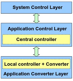
Fig. 2.4 Control structure for power converter (a) conventional (b) proposed layered structure
The system control layer implements control strategies from the system point of view such as power flow control of the transmission line and voltage support control for the
power grid. The system control layer implements the control arithmetic based on information from the application layer and sends operation signals such as duty cycle or control angles to the application layer. The detailed converter operations will be implemented in the application layers. Compared with the conventional solution, the
controller operation is split into two parts, the central controller and the local controller. To modularize the controller, some functions of the controller are distributed to a local controller which is integrated with an HBBB based converter. The central controller
continues to implement all of the control strategy. It sends the switch states only to local controllers instead of switch signals. That greatly reduces the fiber connection requirement. The local controller can also collect the converter information, such as
voltage, current and temperature, and then send it back to the central controller via serial communication to implement the control strategy. More importantly, the local controller can process all of this converter information and protect the converter in fault situations,
such as excessive voltage, excessive current and excessive temperature. The local controller and converter are combined into an intelligent converter which can protect itself regardless incorrect control inputs or interference and support the central controller with enough information for control. Based on these design considerations, the converter
design is modularized, standardized and intelligent. The control calculation burden is distributed and balanced between controller and converter.
Central controller
Local controller + Converter
Application Control Layer
Application Converter Layer
System Control Layer
Central controller
Local controller + Converter
Application Control Layer
Application Converter Layer
System Control Layer
The new control structure concept breaks up the traditional boundaries of control level definitions and forms a more independent layered structure. This modular standard layer
design will simplify power converter applications.
Fig. 2.5 Layered power converter control structure
A digital modular local controller is the key component of the modular converter. In
Switching States
Sensor signals
Switching signals
Communication
Local Controller
Inputs
Outputs
Local Controller
Sensor selector
Fault Signal
Switching States
Sensor signals
Switching signals
Communication
Local Controller
Inputs
Outputs
Local Controller
Sensor selector
Fault Signal
trigger devices, especially for the Emitter Turn-off Thyristor (ETO) device with the build-in sensor functions [44]. That design greatly increases communication reliability.
The prototype of the local controller and its interface are shown as Fig. 2.6
Fig. 2.6 Modular local controller prototype and its interface
The main functions of the local controller are:
·To accept the switch states from central controller and transfer them to switching signals, meanwhile flexible dead time is added to prevent shoot through.
·To gather sensor signals from the converter and translate them into digital signals and send them back to the central controller through serial communication.
Fig. 2.7 shows the function flow chart of a local controller.
Instead of connecting all of the switch signals from central controller to converter, two
switch state signals are sending from central controller to local controller. A three-level converter requires three states to produce three-level output. Two switch states can support four states. An extra state, which is usually used in diode charge mode or in shut down situations, can be used to turn off all the switches.
Fig. 2.7 Function diagram of local controller
This adaptation simplifies the interface greatly. Not only is it suitable for an HBBB
based converter, the switch state’s definition of the local controller is also compatible with NPC (Neutral Point Clamped) topology, and is called diode clamped topology. The switch states and three level outputs of these two topologies are shown in Fig. 2.8 and Fig.
SW1H
SW2H
SW1L
a
n
Vdc
Vdc/2
-Vdc/2
D1
C1
C2
0
SW2L
D1
’SW STATES 00 01 10 11
SW1H 0 0 0 1
SW1L 1 1 0 0
SW2H 0 1 0 1
SW2L 1 0 0 0
Van -Vdc/2 0 X Vdc/2
Fig. 2.8 3-leve NPC converter and switch states
Table 2-2 Communication Protocol of Digital Local Controller
The local controller is able to send all of the information back to the central controller using serial communication via optical fiber. The optical connection increases the
reliability of feedback information. Serial communication has a simple protocol and high reliability, the data protocol is shown in table 2-2.
0-1 2 - 5 6- 14 15 16 -17
Start bit Sensor selector Converter voltage, current and
Vdc
+
SW1H
SW1L
SW2H
SW2L
Output
+
Vdc
+
SW1H
SW1L
SW2H
SW2L
Output
+
SW STATES
00 01 10 11
SW1H 0 0 1 1
SW1L 0 1 0 0
SW2H 0 1 0 1
SW2L 0 0 1 0
Output X -Vdc +Vdc 0
Fig. 2.9 3-level H-bridge converter and switch states
Since the sensor information of the converter is converted and transmitted by the local controller, the local controller can process these signals to implement the protection function.
Fig. 2.10 shows the over-voltage protection. When the voltage exceeds the protection
point, all of the switch signals from the central controller will be blocked and all of the switches will be shut off. When the local controller detects the voltage is below a safe level, it will unblock all of the switches. This over-voltage protection and recovery
Fig. 2.10 Local over-voltage protection function of modular controller (1) voltage (2) fault signal (3) switch in (4) switch to device
Fig. 2.11 shows the over-current protection. When the current exceeds the protection point, all of the switch signals from central controller will be blocked and the converter
will be shut off until the central control sends the command to release the protection. Having all of these functions, the local controller can be integrated with a three-level power converter to form a new converter structure. This modular design makes the modularization and standardization of converter design possible. With the modular
design of converter and controller, the cost of the power converter control system can be reduced significantly. Consider the converter in the Flexible AC Transmission System (FACTS) as an example, the conventional converter costs $120 - $150 per kVA, while by
using the proposed control structure, the estimated cost of converter will be reduced to less than $50 per kVA.
2.4.
Distributed Power Flow Controller Design
The proposed converter-based distributed power flow controller has a single phase H-bridge based ETO light converter, modular controller and communication links.
Unlike conventional solutions, it connects to the power line directly without a
transformer because of its high voltage and current capability. The rating of ETO light converter (1-2 MVA) is suitable for typical 138kV-500kV power transmission line applications. The communication between distributed power flow controller and station
V1 (θ1) Line impedance V2 (θ2)
DPFC module Bypass switch
Station control
V1 (θ1) Line impedance V2 (θ2)
DPFC module Bypass switch
Station control
DPFC module
Va1 (θa1) Va2 (θa2)
Va1 (θb1) Vb2 (θa2)
Va1 (θc1) Va2 (θc2)
DPFC module
Va1 (θa1) Va2 (θa2)
Va1 (θa1) Va2 (θa2)
Va1 (θb1) Vb2 (θa2)
Va1 (θb1) Vb2 (θa2)
Va1 (θc1) Va2 (θc2)
Va1 (θc1) Va2 (θc2)
Fig. 2.12 Single phase distributed power flow controller
Because of the fully modular design, the proposed distributed power flow controller can be installed to the transmission line flexibly based on the power transmission
requirement, for example, one DPFC module per 30 miles. Fig. 2.13 shows the DPFC application diagram in a three phase power transmission system.
A controlled power transmission line implemented with multiple distributed power flow controllers can result in significant benefits:
• Enhancement of the transmission line capability and stability by changing the line
impedance characteristic.
• Reduction of the cost comparing with existed FACTS series compensator
• Enhancement of reliability by applying multiple applications thus achieving
redundancy
• Reduction of the time required to design and build by using standard modular
design
This modular design and modular control of megawatt distributed power flow
controller creates important opportunities in the power transmission system.
2.5.
Operations of DPFC
The DPFC have five operation modes
(1) Stand by mode: the controller is out of service, the bypass switch S1 is turned on to pass the line current
(2) Diode Charge mode: when the operation command arrives, S1 is turned off and line current will go through converter and charge the capacitor
(3) PWM charge mode: when the voltage of DC capacitor is charged to some level, the