ROH, SANGCHUL. Design of Novel Functional Colloidal Suspensions and Gels by Interfacial Engineering of Multiphasic Systems. (Under the direction of Dr. Orlin D. Velev).
Polymeric materials are pervasive in many industrial products because of their simple processability, low cost, low density, excellent mechanical properties and decreased environmental impact. The morphology and functionality of polymeric materials need to be engineered for their use in industrial products. This dissertation describes application of the colloids and interface phenomena in multiphase systems to manufacture a few new classes of polymeric materials with unique morphologies and functionalities. Three categories of multiphase systems have been studied: 1) miscible liquid-liquid pair with immiscible solid, 2) immiscible liquid-liquid pair with immiscible solid particles and 3) liquid mixture inclusion in an immiscible and crosslinkable liquid medium.
Chapter 2 describes the fabrication of a new class of soft dendritic colloids (SDCs or dendricolloids) on the basis of a miscible liquid-liquid pair with immiscible solid multiphase system. The multiphasic system utilizes polymer precipitation in turbulently sheared nonsolvent medium. In the turbulent medium, the polymer solution is randomly stretched and further templated by phase separation induced by solvent-nonsolvent exchange at the interface. This results in soft dendritic colloids which are hierarchically structured, with a big branched corona of nanofibers spreading out in all directions. The biomimetic similarity of their structure to the gecko lizards’ setae renders SDCs with excellent adhesion and cohesion properties.
nonwoven-like materials as well as aerogels made by MPNs are introduced.
In chapter 4, we introduce a new 3D-printing ink consisting of silicone materials in a multiphase system, which utilizes immiscible liquid-liquid pair with immiscible solid particles. The ink is a capillary suspension containing PDMS in the form of both pre-cured microbeads and uncured liquid precursor, dispersed in water as the continuous medium. Owing to strong capillary forces resulting from the PDMS liquid precursor, the suspensions behaved like thixotropic pastes, which are extrudable at high shear stress and possess at low shear stress the high storage moduli required for 3D-printing via direct ink writing. The liquid PDMS bridges were thermally crosslinked after the extrusion, resulting in structures that were remarkably elastic and flexible.
Multiphasic Systems
by Sangchul Roh
A dissertation submitted to the Graduate Faculty of North Carolina State University
in partial fulfillment of the requirements for the degree of
Doctor of Philosophy
Chemical Engineering
Raleigh, North Carolina 2019
APPROVED BY:
_______________________________ _______________________________ Dr. Orlin D. Velev Dr. Michael Dickey
Committee Chair
_______________________________ _______________________________ Dr. Saad Khan Dr. Richard Spontak
ii DEDICATION
iii BIOGRAPHY
iv ACKNOWLEDGMENTS
I would like to express my most sincere appreciation to my advisor, Dr. Orlin D. Velev for his guidance through the entire research. His advice and support made this research possible. I am very thankful for his valuable advice not only on research but also on career development which has shaped me to be the researcher that I am. I am always inspired to follow in his footstep to become a great scientist and teacher.
I was very fortunate to work with great colleagues in the Velev Research group. Dr. Bhuvnesh Bharti and I worked together to design a new 3D printing ink. Austin Williams worked with me for soft dendritic colloids and mesoporous polymer nanosheet project. Drs. Koohee Han, David Chang and Suk-Tai Chang provided laboratory assistance and constructive advice. My research could not be done without supports from many colleagues in the department of Chemical and Biomolecular Engineering. Dr. Dishit P. Parekh from Dr. Dickey group worked on 3D printing silicone materials with me. Dennis T. Lee and Seif Yusuf helped me with measuring surface area of materials.
Many thanks to my committee members, Drs. Richard Spontak, Saad Khan, Michael Dickey, and Joseph Tracy. Their constructive advice and comments were very helpful towards the completion of my research. I appreciate Drs. Saad Khan, Michael Dickey and Lilian Hsiao for letting me use their experiment equipment including the 3D printer, the rheometer, the tensile testing machine, and the goniometer.
v TABLE OF CONTENTS
LIST OF FIGURES ... vi
Chapter 1: Soft Materials Fabrication by Interfacial Templating and Capillary Engineering in Multiphasic Liquids ... 1
1.1. Introduction: Multiphasic Liquid Systems for Structured Soft Materials ... 2
1.2. Nanomaterials made by polymer precipitation in sheared liquid phases ... 4
1.3. Particle structures bound by multiphasic liquids ... 10
1.4. Novel solid-liquid biphasic composites for stimulus-responsive material design ... 14
1.5. Layout of this dissertation ... 18
Chapter 2: Soft Dendritic Colloids with Extraordinary Networking, Adhesion and Structuring Properties ... 19
2.1. Introduction ... 20
2.2. Materials and methods ... 21
2.3. Results ... 23
2.4. Conclusions ... 34
Chapter 3: Mesoporous Polymer Nanosheets via Continuous Shear-Driven Phase Separation and Exfoliation... 35
3.1. Introduction ... 36
3.2. Materials and methods ... 38
3.3. Results ... 39
3.4. Conclusions ... 48
Chapter 4: 3D Printing by Multiphase Homocomposite Silicone/Water Capillary Inks .... 49
4.1. Introduction ... 50
4.2. Materials and methods ... 52
4.3. Results ... 54
4.4. Conclusions ... 64
Chapter 5: Design and Characterization of Transparency-Changing Biphasic Composites with Refractive Index Control ... 65
5.1. Introduction ... 66
5.2. Materials and methods ... 68
5.3. Results ... 69
5.4. Conclusions ... 80
vi LIST OF FIGURES
Figure 1.1 Schematics of three principal approaches of using multiphasic liquid to make
novel materials. ... 4
Figure 1.2 Schematic of the series of concurrent processes leading to the formation of various polymer structures during the shearing of solution droplets. ... 6
Figure 1.3 Examples of polymer and biopolymer structures formed during the shear-directed multiphasic materials formation process... 8
Figure 1.4 The formation of soft capillary materials from particles bound by multiphasic liquid can be based on two principally different configurations depending on the contact angle of the secondary liquid on the particles ... 11
Figure 1.5 Representative structures made of particles assembled by means of multiphasic liquid adsorption, wetting, bridging, and binding ... 13
Figure 1.6 Strategies for fabrication of soft stimulus-responsive composites containing active liquid droplets. ... 14
Figure 1.7 Representative examples of stimuli responsive composites with liquid inclusion ... 16
Figure 2.1 Fabrication, morphology, and structure-enabled applications of soft dendritic colloids ... 24
Figure 2.2 Conditions for dendricolloid formation ... 26
Figure 2.3 Adhesion characteristics of soft dendritic colloids ... 28
Figure 2.4 Structuring capability of soft dendritic colloids in liquid suspensions ... 33
Figure 3.1 Schematics of formation of mesoporous polymer nanosheet ... 40
Figure 3.2 Morphology of polyacrylonitrile (PAN) nanosheets ... 41
Figure 3.3 Pore size change based on solvent and nonsolvent affinity ... 43
Figure 3.4 Morphology of MPNs according to precipitation rate ... 45
Figure 3.5 Materials assembled with mesoporous nanosheets ... 47
Figure 4.1 Principle of 3D printing process of PDMS particle suspension with capillary bridges ... 54
vii Figure 4.3 Morphologies and mechanical properties of crosslinked PDMS inks ... 59 Figure 4.4 Examples of 3D printed ultraflexible PDMS structures made after curing of
capillary-bridged bead suspensions ... 62 Figure 5.1 Fabrication and photographs of WG/PDMS biphasic composites (WPBCs) ... 71 Figure 5.2 Optical response of WPBCs to osmotic pressure when present in a water
medium... 73 Figure 5.3 Changes in swelling and optical properties of WPBCs in WG immersion
medium... 75 Figure 5.4 Changes in optical properties of WPBCs exposed to various immersion media ... 78 Figure 6.1 Unusual properties of hydrogels reinforced with dendricolloids ... 85 Figure 6.2 Soft magnetic actuator fabrication by Homocomposite Thixotropic Pastes
1 CHAPTER 1
Introduction: Soft Materials Fabrication by Interfacial Templating and Capillary Engineering in Multiphasic Liquids
Partially based on
2 1.1. Introduction: Multiphasic Liquid Systems for Structured Soft Materials
The development of new processes for making polymeric and composite materials with nanoscale structure, high surface area and engineered properties is a research topic of large academic and industrial interest. Such materials are of broad importance and have numerous technology applications. Polymer nanomaterials are ubiquitous as they can be the key components in the formulation of pharmaceutics,[1–3] agricultural products,[4] food products,[5,6] catalysts,[7–9] filtration membranes,[10–13] adsorbents,[14,15] coatings,[16] and many others. The polymeric nanomaterials could be inexpensive and can be synthesized with highly customized composition from variety of nature-abundant resources. Moreover, polymer nanomaterials are overall more environmentally friendly than many inorganic and metallic nanomaterials due to their low toxicity and ability to be biodegradable.[1,3] In another difference from inorganic or metallic materials, the polymeric materials have low melting temperature and solution-based processability.[12,13,17] Researchers have shown numerous approaches of how one can fabricate various polymeric nano- and micro-materials on large scales with a multitude of methods including particle templating,[18] block copolymer self-assembly,[8,9] emulsion polymerization,[19,20] antisolvent precipitation,[21] solution casting,[12] spraying,[22] fiber drawing, and spinning.[23,24]
3 liquid/liquid/solid systems as the basis for functional materials synthesis and nanofabrication. We describe three groups of liquid/liquid/solid system processes leading to new materials formation. The first one involves the use of polymer precipitation in sheared liquid phases to make structures, such as nanofibers, nanorods, and nanoribbons. The second class of material structures involves the use of capillary binding in the making of ultrasoft gels and thixotropic phases. The last type includes fabricating functional soft materials by dispersing stimulus-active liquid domains in a solid matrix.
4 Figure 1.1. Schematics of three principal approaches of using multiphasic liquid to make novel materials. (a) The precipitation of the polymer dissolved in the liquid droplets L1 under specific flow conditions leads to formation of various types of materials morphologies. (b) The capillary binding of solid particles by liquid could be used in the making of new materials. (c) The liquid
droplets in a biphasic system can make functional materials controlled by the droplet composition and properties.
1.2. Nanomaterials made by polymer precipitation in sheared liquid phases
5 research performed to date proves that polymer materials with highly developed morphologies can be produced in a predictable and controlled way by this type of processes. The established process control parameters include polymer concentration, polymer molecular weight, solvent-medium miscibility, and shear stress of medium. By controlling these parameters, we successfully fabricated a number of useful polymer nano/microstructures, including nano/microspheres, nanoribbons, nanofibers, and nanosheets.
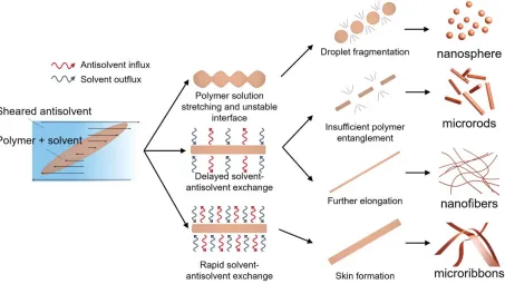
6 Figure 1.2. Schematic of the series of concurrent processes leading to the formation of various
polymer structures during the shearing of solution droplets. Depending on the rate of solvent/antisolvent exchange and the polymer precipitation patterns, the process can result in micro- and nanoparticles, rods, nanofibers, microribbons, and a range of other structures.[25–27]
Solutions of polymers with moderate molecular weight and concentration lower than the entanglement one can be stretched when subjected to the shear stress of the medium. The initially antisolvent-precipitated and stretched polymer proto-fibers under shear stress were made of epoxy resin. The use of epoxy makes them brittle and prone to fragmentation. The resulting fragmented particles are in the form of microrods (Figure 1.2). Our group discovered and reported how microrods from SU-8 and other polymers are formed in this regime, and demonstrated that these rods can be used for Pickering foam and emulsion “superstabilization” (Figure 1.3(b)).[28,29]
7 materials such as nanoribbons, nanofibers, and nanosheets. The morphological outcome of the nanomaterial precipitation process is determined by the competition between precipitation rate and shear rate of medium.[26] At a fixed shear rate, the precipitation rate is highly dependent on the efflux rate of the solvent and influx rate of the antisolvent. These diffusion rates are proportional to the chemical potential gradient (𝛻𝜇) and diffusion coefficient D. 𝛻𝜇 tends to be low when the
8 Figure 1.3. Examples of polymer and biopolymer structures formed during the shear-directed multiphasic materials formation process. (a) Lignin nanoparticles,[25] (b) SU-8 polymer microrod
(scale bars = 100 and 10 μm, inset),[27] (c) nanofibers (Scale bar = 2 μm) and (d) nanoribbons from polystyrene (scale bar = 10 μm).[26]
When the stretching and precipitation rates in the four-component system are balanced, the diameters of resulting nanofibers can be controlled by the shear stress of medium. The shear-driven extension in the liquid/liquid emulsion system is a result of the balance of two parameters; shear stress (τs) and interfacial tension and is described by the capillary number (Ca). During droplet elongation, the viscous force exerted by the continuous phase has to be high enough to overcome the interfacial tension between the liquid phases. When Ca is low, the polymer solution is broken into droplets and emulsified by the interfacial instability. Microparticles are formed after polymer precipitation. When Ca is high, the polymer solution droplets are stretched, and nanofibers can be fabricated in a simple shear process. The diameter (d) of these nanofibers decreases with the shear
stress, following the relationship, 𝑑 ∝𝐶𝑎
𝜏𝑠. Nanofibers (d < 200 nm) can be fabricated at high shear
rates, inducing large stresses on the extending droplets (τs ≈ 200 Pa).
9 can be easily scaled up for continuous fabrication of nanofibers at very high rates. The patented[30– 32] XanoShear technology can increase drastically the scale and scope of industrial nanofiber
10 1.3. Particle structures bound by multiphasic liquids
In this section, we review a second approach for making novel materials from systems incorporating multiple liquid phases and particles. It is based on the collection, adsorption, binding, and capillary interactions of particles inside immiscible liquid dispersions (Figure 1.4). The structural response of these materials can be engineered by using both capillary interactions at the liquid/liquid interfaces and colloidal particle/particle interactions. In general, such structures can be classified in two broad categories based on the geometrical relations between the particles and the “inner” liquid phase. The first, widely investigated, system consists of particle structures,
11 Figure 1.4. The formation of soft capillary materials from particles bound by multiphasic liquid
can be based on two principally different configurations depending on the contact angle of the secondary liquid on the particles.
The second principal class of liquid/liquid/particle structures is one where the inner liquid phase forms capillary bridges between the particles (Figure 1.4). Various types of such structures have been made under the general name of “capillary suspensions.”[42–45] The simplest example of
12 Apart from the paste- or gel-like materials, we can further design new nanomaterials held together by capillary bridging forces. One example from our group’s research is using capillary bridging force for making of ultraflexible filaments composed of iron oxide nanoparticles (γ-Fe2O3) surrounded by lipid layers (Figure 1.5(d)).[51] The water-immiscible and hydrophobic lipid layers on the γ- Fe2O3 particles form nanocapillary bridges between the adjacent nanoparticles under the
13 Figure 1.5. Representative structures made of particles assembled by means of multiphasic liquid adsorption, wetting, bridging, and binding. (a) A colloidosome composed of 1-octanol
emulsion droplet decorated with latex particles (scale bar = 10 μm).[33] (b) Colloidosome capsules from SU-8 microrods around decane droplets.[29] (c) A supraparticle ball assembly of
latex particles and gold nanoparticles (scale bar = 500 μm). The supraparticle was formed by drying of colloidal suspension droplet on a superhydrophobic surface.[37] (d) Iron oxide γ- Fe2O3
nanoparticles with a lipid nanocapillary bridge.[53] (e) Two-dimensionally percolated network composed of γ- Fe2O3 nanoparticles with liquid nanocapillary bridges. [53] (f) Patchy particle
14 1.4. Novel solid-liquid biphasic composites for stimulus-responsive material design
In this section the basics of making soft, liquid-in-solid biphasic composites that could respond to external stimuli will be reviewed. Stimuli-responsive composites have gained significant amount of attention from researchers because of their potential applications in smart and intelligent materials, biomedical devices, and soft robot fabrication. Upon exposure to external stimuli such as temperature,[54,55] electric fields,[56,57] magnetic fields,[58,59] solvents,[60,61] salinity,[62] or mechanical stress,[63] responsive materials undergo some change of their physical states including optical properties, tensile/shear moduli, and/or shapes.[62]
One strategy for designing stimulus-responsive materials is the inclusion of immiscible liquid in a soft matrix such as elastomers or hydrogels (Figure 1.6(a)). The liquid-in-solid biphasic materials can be readily fabricated by shear driven emulsification[62] or phase separation by changing solvent composition or temperature.[56] The size of the droplet, which largely governs the bulk properties of the composite, can be readily controlled using various types of interfacial stabilizers or shearing processes. The solidification of the matrix material following emulsification can immobilize the immiscible liquid droplets within the material.
Figure 1.6. Strategies for fabrication of soft stimulus-responsive composites containing active liquid droplets. The liquid droplets may be composed of anisotropic liquid (Type 1), colloidal
15 In such biphasic materials, optical light scattering makes the composite opaque due to the refractive index mismatch between the matrix material and the liquid droplets.[64] The optical clarity of the biphasic composite can be engineered by adjusting the refractive index of droplets, the size of the droplets (on the range of > 1 μm), or the concentration of the droplets.[64] Therefore, any changes in physical state of the droplet phases by an external stimulus can further change the bulk materials’ optical property.
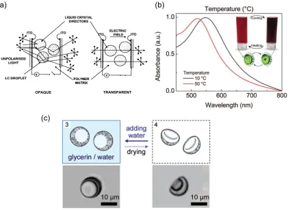
We categorized three types of systems characterized by their stimuli-responsive capabilities in the liquid droplets reported in the literature (Figure 1.6). One of traditional and highly studied systems is polymer-dispersed liquid crystal (PDLC) (Type 1 in Figure 1.6). Liquid crystals have anisotropy in dielectric properties, which allows orientation along an electric field. Also, liquid crystals have two orientation-dependent refractive indices known as the extraordinary refractive index, ne, and the ordinary refractive index, no. Within the PDLC film, the liquid crystals are 1~2 μm spherical structures and the nematic director of each droplet has different orientations
from one droplet to the next.[56] This further intensify the light scattering effect, making the PDLC film highly opaque. When an electric field is applied across the film, the liquid crystals align so that the normally incident light only sees medium with no. When no ~ np (refractive index of polymer), the PDLC film becomes transparent (Figure 1.7(a)). The optical property change is instantaneous (< 1 s) and highly reversible.
16 the alkane droplet and aggregate at elevated temperature. As a response to the agglomeration, the gold suspension changes color exhibiting varied plasmon peak positions. Therefore, these authors were able to successfully design color changing composites that are temperature-responsive. Because the gold nanoparticle aggregation is highly reversible, the composite’s optical response
is also reversible.
Figure 1.7. Representative examples of stimuli responsive composites with liquid inclusion. (a) Polymer dispersed liquid crystal.[56] (b) A nanocomposite with liquid inclusions of a responsive
nanoparticle dispersion.[54] (c) A shape morphing microcapsule by swelling of inner liquid phase.[62]
17 components or other species can bring about physical changes in the immobilized liquid droplets. One example of such structure is given by Velev and coworkers, who fabricated multi-stimuli responsive microcapsules using emulsification (double emulsion). The capsules are composed of water/glycerol mixture droplet in an elastomeric matrix. The microcapsules can change shape and volume by swelling and deswelling in water and a dry environment, respectively, because of the chemical potential difference of water across the elastomeric shell. If active ingredients are added to the inner droplet phase, the microcapsules may find applications such as drug delivery and microreactors.[62]
18 1.5. Layout of this dissertation
19 CHAPTER 2
20 2.1. Introduction
The interplay between morphology, excluded volume, and adhesivity of particles critically determines the physical properties of numerous materials such as gels, suspensions, emulsions, foams, and coatings.[27,67–69] The structure-building and gel-forming abilities of colloids in liquid can be enhanced by using branched and fractal particles such as fumed silica,[70] “hedgehog” nanoparticles,[68] nanofibrillated cellulose[71] or long branched aramid nanofibers.[69] The adhesion of particles in gels can be increased by capillarity.[43] One other mechanism of achieving strong adhesion exhibited in nature involves the breaking of a single contact into numerous finer subcontacts (“contact splitting”) as seen in the feet of gecko lizards and spider webs.[72–79] The
finding that the mats of branched nanofibrils on the bottom of gecko feet stick strongly to nearly any substrate has been explained by the high contact area that maximizes the van der Waals forces.[72,73,77] It has inspired the development of synthetic dry adhesives that mimic this effect.[75,77,80–84] The extraordinarily strong adhesion of the nanofibrillar mats of gecko legs is also closely associated with the branching of the fibrils, which allows redistribution of the stress between the substrate and the nanofiber setae.[74,85,86]
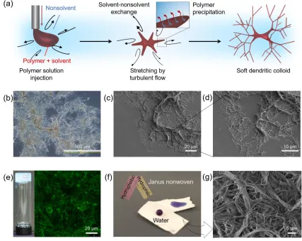
Here, we describe how the principles of fractal branching and nanofibrillar contact splitting can be implemented into a class of hierarchically structured polymeric colloids with branched nanofiber coronas. Due to their morphological analogy to dendrite-type structures, we name them “soft dendritic colloids”. We show that these nanofibrillar structures exhibit several highly unusual
21 2.2. Materials and methods
2.2.1. Fabrication of soft dendritic colloids
We demonstrate dendricolloids composed of polystyrene (PS, Mw: 230,000, Sigma-Aldrich), cellulose acetate (CA, Mn: 30,000, Sigma-Aldrich), polyvinyl alcohol (PVOH, Mowiol® 18-88, 86.7 - 88.7% hydrolysis, MW: 130,000, Sigma-Aldrich), and polyvinylidene fluoride (PVDF, Mw: 530,000, Sigma-Aldrich). The polymer solution concentrations, solvents, and nonsolvents for fabricating dendricolloids are listed in Table 1. The polymer/solvent mixture was directly injected into the shear zone of the IKA Magic Lab® device at 20,000 rpm (Figure A1 in Appendix A). The PVOH dendricolloids were crosslinked with glutaraldehyde in acetone. All samples were washed with water and stored as ethanol or water suspensions.
2.2.2. Lap shear testing
22 mixture for 2 hours. To remove unreacted substances, we used 100 ml of toluene, isopropyl alcohol, acetone, and water under sonication. After cleaning, the hydrophobized glass slides were placed in a vacuum oven (105 ºC) for 24 hrs.
2.2.3. Porous nonwoven fabrication
To create a nonwoven (paper-like) material, 10 mL of 0.5 wt.% dendricolloid in ethanol suspension was deposited on a polytetrafluoroethylene (PTFE) sheet (McMaster, USA). The PTFE sheet with dendricolloid suspension was then placed in an oven (65 °C) to dry. After drying, the dendricolloids form a nonwoven sheet that is easily removed from the PTFE surface.
2.2.4. Rheology characterization of dendricolloid suspensions
23 2.3. Results
2.3.1. Morphology and conditions for formation of soft dendritic colloids
24 Figure 2.1. Fabrication, morphology, and structure-enabled applications of soft dendritic colloids. (a) Schematic of the process leading to dendricolloid formation. The polymer solution
is injected into a turbulently sheared nonsolvent medium. Upon injection, it is randomly stretched by turbulent eddies and the polymer is precipitated into a branched structure. (b) An optical microscopy and (c,d) scanning electron microscopy (SEM) images of PS dendricolloids. The colloids are hierarchically branched and surrounded by a nanofiber corona. (e) A photograph
of a vial containing a gel of 0.5 vol.% of cellulose acetate dendricolloids in polyethylene glycol and a confocal microscopy image of its structure. The fibrils were labelled with fluorescein isothiocyanate. (f) A photograph of a “Janus” nonwoven sheet composed of dried dendritic fibrillar layers of PS (superhydrophobic) and PVOH (superhydrophilic). (g) SEM image of the
25 2.3.2. Conditions for formation of soft dendritic colloids
The polymer structure of the colloidal materials formed in the process is controlled by multiple factors, including the hydrodynamics of shear, the initial polymer concentration in the injected solution, and the rates of solvent-nonsolvent mixing and polymer precipitation. We found that the key factor for formation of dendritic structures is the turbulent flow. Polymer solutions precipitated under laminar flow yield nanofibers as described in our earlier report.[26] However, when the nonsolvent medium was turbulently sheared, the precipitated structures were dendritic colloids (Figure. 2.1(a-d) and Figure A2 in Appendix A). We next varied the rate of polymer precipitation and observed the structure of PS dendricolloids formed. This was achieved by changing the polymer concentration and the chemical composition of the solvent/non-solvent mixture. The diverse structural outcome is summarized in Figure 2.2(a). Dendritic nanofibrils were precipitated when the PS was dissolved in tetrahydrofuran (THF) at a concentration range of 5 ‒ 10 wt.%. PS
26 structures. We hypothesize that the hierarchically self-similar structure of the dendricolloids is templated by the fluid eddies in turbulent flow, which has stochastic fractal organization.[87]
Figure 2.2. Conditions for dendricolloid formation. (a) Fluorescence microscopy images of polystyrene particulates (labeled with Nile red) precipitated in a turbulently sheared water
medium at different solvent-nonsolvent pairings (horizontal) and polymer solution concentrations. Sheet-like particles were precipitated from solvents with high affinity to water (DMF, DMSO, and 1,4-dioxane). When PS was dissolved in THF, dendritic polymer structures
were formed at a certain concentration range (5-10 wt.%). Lower or higher polymer concentrations result in small particle or sheet-like particles, respectively. (b) Ternary phase diagram of PS, water (nonsolvent), and solvents. Our hypothesis is that the phase trajectory of
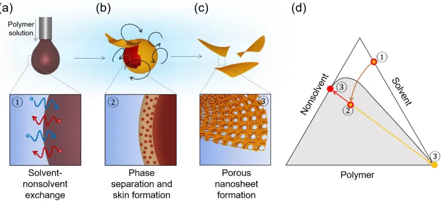
precipitation determines the morphological outcome. The composition paths of a polymer/solvent droplet after injection demonstrate ① rapid precipitation for DMF-Water system and ② delayed precipitation for THF-Water. (c) Schematic of the mechanism of
sheet-like and soft dendritic colloid formation depending on composition paths shown in graph (b). Rapid precipitation results in sheet-like particulates, while delayed precipitation leads to
27 2.3.3. Adhesion property of soft dendritic colloids
The branched nanofibers surrounding the soft colloids lead to remarkable adhesive properties. We evaluated their adhesion strength through lap shear strength testing. To prepare the specimens, 250 µl of 1 wt.% CA dendricolloid suspension in ethanol was dried in the gap between two glass slides (overlap area of 25×13 mm). The tensile lap shear curves of these specimens are shown in Figure 2.3(a). The lap shear stress of the CA dendricolloids on the glass substrate was as high as ~ 425 N (1.3 MPa). This is a remarkable strength for such a small amount of dried particulate adhesive (~ 2 mg) – for example, this tensile stress was higher than the one of commercial 2-sided Scotch tape (~1.04 MPa). Dendricolloids composed of other polymers also exhibited commensurate lap shear strengths, e.g., polyvinylidene fluoride and polyvinyl alcohol nanofibrils exhibited lap shear strengths of ~ 107.2 N and 870.9 N, respectively (Figure A3).
28 (Figure 2.3(c)). Thus, we conclude that capillary forces cannot account for the strong dendricolloid adhesion.
Figure 2.3. Adhesion characteristics of soft dendritic colloids. (a) Lap shear strength curve of a cellulose acetate dendricolloid layer between glass slides. The inset shows a magnified cross-section of the dendritic fibers on the substrate. (b) Example of the efficiency of these particles as
dried adhesives between glass plates bound by 2 mg of CA dendricolloids in the white patch above and two-sided Scotch tape on the bottom. The Scotch tape adhesive fails before the dendritic network. (c) Maximum lap shear strength of CA dendricolloids deposited between pristine and hydrophobized glass substrates within air (red column, biggest refractive index difference, |n12- n32|=1.16), diiodomethane (blue column, moderate RI difference, |n12- n32|=0.87) and polyethylene glycol 400 (purple column, RI-matched solution, |n12- n32|=0.01). These results prove the major role of the van der Waals forces in the adhesion. (d) Lap shear strengths of equal amounts of CA nanoparticles and dendricolloids between two glass slides (red bars), compared to
29 The alternative hypothesis is that the strong adhesion originates predominantly from van der Waals attraction of the nanofibrils to the substrate. We evaluated the effect of these universal forces by measuring the lap shear strength of adhesive patches of dendricolloids infused with organic liquids. According to Lifshitz theory, the van der Waals interaction depends strongly on the refractive index difference between the polymer nanofibrils and the surrounding medium.[90] The lap shear strength of CA dendricolloid binding will be minimized when the refractive index (RI) of the infused liquid medium matches that of CA.[90] The media included polyethylene glycol (PEG 400) and diiodomethane, the RIs of which are ~ 1.466 (matching the CA RI = 1.47), and ~ 1.74, respectively. While there was a two-fold decrease in lap shear strength with diiodomethane, the lap shear strength of both pristine and hydrophobized glass reached a deep minimum when the infused liquid matched the RI of the CA dendricolloids (Figure 2.3(c)). This proves that the dendricolloid adhesion is predominantly driven by van der Waals forces, which has been established as the basis of the “gecko leg” effect.[72,73]
30 Another example of the properties resulting from the hierarchical structure and physical stickiness of the nanofibrillar coronas is the strong adhesion to various surfaces and to each other on drying, enabling the facile formation of superhydrophilic or superhydrophobic coatings and nonwoven sheets. The nonwovens are readily formed by drying of dendricolloid suspensions on a Teflon substrate, yielding a porous sheet, that can be peeled off due to the low van der Waals adhesion to Teflon. These nonwovens are flexible, bendable, and foldable without the addition of physical or chemical binders. Examples of porous sheets fabricated by drying of CA, PS, and polyvinyl alcohol (PVOH) dendricolloid suspensions in ethanol are shown in Figure 2.1(f) and Figure A6. The mechanical integrity of these nonwovens indicates strong cohesivity of the fibrillar network. In addition, their hierarchically rough surface porous structure engenders superhydrophobicity or superhydrophilicity depending on the wettability of the polymer comprising the material. For instance, the apparent water droplet contact angle on nonwoven composed of polystyrene dendricolloids is > 150º with a sliding angle of 3.5º (as compared to a Young’s contact angle on flat PS of 89º), while PVOH nonwovens have a water contact angle near
31 2.3.4. Extraordinary networking and structuring properties of soft dendritic colloids
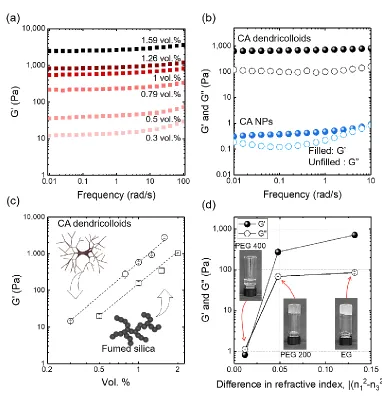
The soft dendritic colloids proved to be highly efficient thickening and gelation agents within liquid media. For example, as little of 0.5 vol.% CA dendricolloids lead to gelation of polyethylene glycol (PEG 200) by forming a voluminous fibrillar network as shown in Figure 2.1(e). The effect of dendritic colloids as rheological modifiers was evaluated via the dependence of storage modulus (G′) and loss modulus (G″) on the volume fraction of suspensions in mineral oil (Figure 2.4(a) and
Figure A8 in Appendix A). All samples exhibited gel-like properties in the linear viscoelastic regime with G′ >> G″ independent of frequency. To confirm the role of fractal morphology on suspension rheology, we compared the G’ and G″ of 1 w/v. % of CA dendricolloid and CA
nanoparticles in ethylene glycol (Figure 2.4(b)). The dendricolloid suspension exhibited gel-like behavior, with G′ > G″ and both moduli being 3-4 log larger than fluid-like nanoparticle
suspensions. Notably, after all suspensions were heated to 180 °C for 20 minutes causing the dissolution of the CA particles into ethylene glycol, the G′ and G″ of all CA solutions collapse into a nearly identical curve (Figure A9 in Appendix A).
Finally, the gelation efficiency of the soft dendritic colloids was compared to the most common “hard” dendritic colloid used as a commercial rheology modifier – fumed silica (FS). The G′ of mineral oil suspensions composed of CA dendricolloids and fumed silica are shown in Figure
2.4(c). The hydrophilic FS forms fractal aggregates and a 3D network structure in hydrophobic liquid such as mineral oil.[70] Both fumed silica and CA dendricolloid suspensions exhibited gel-like behavior (G′ >> G″ and G′ ≠ G′(ω)), however, at each volume fraction the G′ of the CA
32 We investigated the contribution of van der Waals interactions to the dendricolloids rheology characteristics by the RI matching technique. CA dendricolloids were suspended in ethylene glycol (EG), PEG 200 and PEG 400. The transition to nearly transparent, RI-matched suspension in PEG 4000, correlated to change from highly elastic, gel-like behavior to weakly elastic, fluid-like one (Figure 2.4(d) and Figure A12 in Appendix A). Given the strong dependence of the yield stress, G′, and G″ of the suspensions on the refractive index difference (Figure
33 Figure 2.4. Structuring capability of soft dendritic colloids in liquid suspensions. (a) Storage modulus
(G′) vs. frequency of CA dendricolloids suspensions in mineral oil with varying vol. fractions. (b)
Magnitude of the G’ and G” of 1 w/v % of CA dendricolloids (black), and CA nanospheres (blue) in ethylene glycol. The dendritic morphology leads to 3~4-order increase of the magnitude of both moduli. (c) Dependence of the storage modulus (G’) on the volume % of CA dendricolloids (○) and fumed silica (□) in mineral oil at a frequency of 1 rad/s. At any volume fraction, the CA dendricolloids have higher efficiency in increasing the storage modulus of mineral oil. (d) The change in storage modulus (G’, filled)
and loss modulus (G”, unfilled) of 1 w/v. % of CA dendricolloid vs. the difference between the refractive indices of the polymer and PEG media (related to the van der Waals force) at 1 rad/s. A dramatic decrease
34 2.4. Conclusions
In summary, we present here a class of soft matter with a dendritic morphology and exceptional adhesion and structuring properties. The dendricolloids fill a previously little explored size domain of fractal soft matter. The dendricolloids are orders of magnitude larger than the molecular polymer dendrimers that have been of large interest previously.[92–94] Their nanofiber coronas lead to strong adhesion to almost any surface because of van der Waals attraction. This strong adhesion was shown to be similar in physical origin to the unusual “stickiness” of the legs of the gecko lizards.
35 CHAPTER 3
36 3.1. Introduction
Mesoporous materials play an important role in many industrial applications such as catalysts, energy storage materials, membranes, and biomaterials due to their high surface area.[95] While metals and ceramics can be manufactured into mesoporous structures,[96,97] using soft polymeric materials is advantageous due to controlled synthetic control, facile surface modification, and low cost.[98–100] In this light, recent efforts have been made to synthesize mesoporous polymers by block copolymer templating,[100] as well as thermal[101] and polymerization induced phase separation.[99]
Nonsolvent-induced phase separation (NIPS, immersion precipitation) is of great interest for porous material fabrication due to its simple processability as well as scalability.[12,102] In the NIPS process, the polymer and nonsolvent both are miscible with a solvent but not with each other. When the polymer/solvent mixture (polymer solution) is immersed into the nonsolvent medium, the polymer solution forms pores as a result of the solvent-nonsolvent exchange subsequent to phase separation. The sizes of pores are dictated by solvent-nonsolvent affinity and the rate of solvent-nonsolvent exchange.[12,103–105] When the solvent-nonsolvent affinity is high, the immersed polymer solution immediately forms thin (~ 0.2 μm) and mesoporous solid skin as a result of rapid solvent-nonsolvent exchange.[106] The skin layer delays solvent-nonsolvent exchange resulting macroporous structure under the skin layer.
37 clays, and many other metal oxides and metal halides in liquid media. Fabricating nanosheets from polymeric materials is relatively challenging because polymer molecules or crystals are randomly oriented.
38 3.2. Materials and Methods
3.2.1. Fabrication of mesoporous nanosheet
The turbulent shear medium was processed in a shear device modified from a colloidal mill machine (IKA Magic lab®). Polystyrene (PS, Mn 140,000 Da) and Polyacrylonitrile (PAN) were purchased from Sigma Aldrich. To dissolve the polymers, we used DMF (Fisher scientific) and pyridine (Fisher scientific). As nonsolvent medium, we used Millipore® water.
3.2.2.Characterization of mesoporous polymer nanosheets
39 3.3. Results
3.3.1. Formation of mesoporous polymer nanosheets (MPNs)
40 Figure 3.1. Schematics of formation of mesoporous polymer nanosheet. (a) Polymer solution is
injected into a turbulently sheared nonsolvent medium. Upon injection, solvent and nonsolvent are exchanged at the interface. (b) At the polymer solution interface, a porous and vitrified skin
is formed followed by being exfoliated. (c) The exfoliated skins are freely suspended in the nonsolvent medium. (d) A ternary phase diagram of polymer-solvent-nonsolvent system. The
grey area and red arrow correspondingly illustrate the two-phase region and the composition trajectory of the polymer solution-nonsolvent interface.
3.3.2.Morphology of mesoporous polymer nanosheets
41 We used field emission scanning electron microscopy (FE-SEM) to visualize the morphology of MPNs at higher magnitude. The wrinkles of the nanosheets are ~ 100 nm elevated indicating that the thickness of the nanosheets are under 100 nm (Figure 3.2(c)). At a higher magnification, the nanosheets are composed of mesopore networks without macropores (Figure 3.2(d)). For representative pore size and corresponding surface area, a surface analyzer which measures nitrogen adsorption and desorption isotherms was used. The specific surface area of the PAN nanosheets was estimated to be 97.79 m2/g using the Brunauer–Emmett–Teller (BET) model at low pressures (p/p0 < 0.3). From the isotherm at higher relative pressures (p/p0 > 0.4), the Barrett–Joyner–Halenda (BJH) desorption model was used to estimate the pore size distribution. The BJH model indicated the average pore width to be 18.21 nm. From the BJH model, the volume of mesopores (diameter: 2 – 50 nm) and macropores (diameter: 50 – 200 nm) were estimated to be 0.51 cm3/g-1 and 0.089 cm3/g-1, respectively.
Figure 3.2. Morphology of polyacrylonitrile (PAN) nanosheets. Dark field optical microscopy image of (a) PAN nanosheets and (b) single PAN nanosheet. Morphology of a PAN nanosheet from FE-SEM at (c) low and (d) high magnification. (e) Characterization of surface area and
42 3.3.3. Conditions for MPN formation
43 Figure 3.3. Pore size change based on solvent and nonsolvent affinity. Optical microscopy (inset) and FE-SEM images of PS nanosheets fabricated from (a) DMF (b) pyridine as solvents. (c) Pore size distribution histogram of nanosheets fabricated from DMF and pyridine as solvent.
(d) Ternary phase diagram of PS/solvent (DMF or pyridine)/water.
44 rapid solvent-nonsolvent exchange in nonsolvent-induced phase separation.[12] To measure the affinities, we utilized the Hansen solubility parameter distance (Ra) which is expressed as 𝑅𝑎2 = 4(𝛿𝑁𝑆𝑑 − 𝛿𝑆𝑑)2+ (𝛿𝑁𝑆𝑝 − 𝛿𝑆𝑝)2+ (𝛿𝑁𝑆ℎ − 𝛿𝑆ℎ)2 where 𝛿𝑑, 𝛿𝑝and 𝛿ℎ represent the dispersive, polar,
45 Figure 3.4. Morphology of MPNs according to precipitation rate. PAN nanosheet morphologies with (a) 0 wt.%, (b) 30 wt.% and (c) 60 wt.% DMF in a shear medium (water). (d) Change in the
size of the nanosheets from different amount of DMF in water. (f) Average pore sizes of the nanosheets from different amount of DMF in water.
46 injected polymer solutions are prone to be fragmented into smaller droplets due to delayed precipitation. Moreover, the slowing of the polymer precipitation by adding DMF in water also results in increase in the pore size of the nanosheets.[12,111] In this light, we can conclude that the size of pores as well as the geometry of the nanosheets could also be controlled by the concentration of the solvent in nonsolvent.
3.3.4. Film and aerogel formation via MPN assembly
The porous polymer nanosheets can be obtained in the form of various macroscale materials due to the superior structuring properties of the sheet-like particulates. Filtration of a 0.1 wt.% PAN nanosheet suspension in ethanol yielded stacked-sheet structures. After drying, we were able to obtain nonwoven materials. An example of such a PAN nonwoven is presented in Figure 3.5(a). The SEM image shows the fractured nanosheet film and its cross-section. The PAN nanosheets were stacked into a lamellar structure because the soft nanosheets were deformed by the capillary force. This lamellar assembly was reported elsewhere with other atomically thin inorganic nanosheets such as graphene, various metal oxides, and metals. The mesoporous film-forming capability may find applications in submicrometer scale Li+ ion battery separators and other ultrathin, water filters with engineered porosities. Our preliminary experiments reveal that freestanding sub-micrometer thickness film can be also fabricated. The ultra-thin porous materials could be very advantageous for reduced pressure drop of water filtration membranes or increased capacity of electrode in Li+ batteries.
47 in water. Through the freeze-drying process, the suspension became a sponge-like aerogel of which density is 0.012 g/cm3. The aerogel is soft and elastic as shown in Figure 3.5(b). The size of pores is defined by the space between the mesoporous sheets may further be controlled by changing the wt.% of MPNs in the water medium. More amount of the MPNs in water is expected to form smaller macropores.
Figure 3.5. Materials assembled with mesoporous nanosheets. (a) Nonwoven-like film formed from PAN MPNs by vacuum filtration. (b) Aerogel fabricated by freeze-drying 1 wt.% of PAN
MPNs in water suspension.
48 3.4. Conclusions
49 CHAPTER 4
50 4.1. Introduction
The 3D printing technology has evolved impressively over the last decade in its ability to fabricate structures with complex topographical features on the micro and macroscale.[113–120] The 3D manufacturing via direct ink writing can shape various types of materials from plastics to metals by nozzle extrusion processes.[60,113,114,119,121–127] The inks for direct writing with polymers mostly contain thermoplastics, which allows hot melt nozzle extrusion followed by rapid cooling and solidification into target shape. It is more difficult to do 3D printing with elastomeric polymers, as their precursors are normally liquid at ambient conditions. The post-ejection curing complicates and slows down the process, which for some polymers can be speeded up by using special UV curing agents.[128]
One of the most widely used elastomeric polymers, polydimethylsiloxane (PDMS), has wide range of applications in the area of advanced materials for biomedical and soft robotics.[125,126,129–133] However, 3D printing with PDMS is challenging as it necessitates special compositions with UV-curable or thixotropic PDMS precursors.[115,130,132,133] Direct ink writing of non-flowable PDMS precursor has been used to fabricate synthetic spider web and micro chambers.[126,130,133] Wax microparticles have been incorporated in PDMS precursors to make gel-like materials forming stable structures after extrusion.[134] More recently, PDMS liquid precursors (LPs) were 3D printed by injection into hydrophilic thixotropic Carbopol gel, which acts as a scaffold/support.[135]
Capillarity can be a powerful alternative tool to shape “soft” 3D structures. Sandcastles
51 bridges are found in concentrated multiphasic suspensions, containing small amount of immiscible liquid with < 90° contact angle on the solid particles.[43,50,139] The interparticle capillary bridges lead to formation of 3D particle networks by pulling the adjacent particles together. These suspensions can have paste-like consistency and significant elastic modulus and static yield stress.[43,50] Such pastes behave as elastic, shape-retaining solids at low stress, and as viscoelastic flowable liquids at high stress. 3D assemblies of glass microbeads (MBs) linked via water capillary bridges by rapid water removal can retain their shape, albeit in fragile structures.[139] 3D printing with capillary bridged structures, however, requires multicomponent mixtures of solid suspension phase, surface-wetting liquid, and continuous medium. The need to simplify such systems begs the question: Can we create capillary suspension inks that use the same elastomeric material both as solid beads and as liquid phase for capillary bridging, which can later be transformed into one single elastomer compound?
52 4.2. Materials and Methods
4.2.1.Synthesis of PDMS Microbeads
The synthesis of PDMS microbeads was performed in two steps: (1) emulsification of PDMS precursors (Sylgard 184, Dow corning) and (2) crosslinking of the emulsified PDMS precursor droplets. 10:1 mixtures of PDMS precursors and curing agents were mixed and degassed in a desiccator under vacuum. Aliquots of 6 mL of PDMS precursors were preemulsified in a 50 mL centrifuge tube containing 30 mL of 14 wt% polyvinyl alcohol (Mowiol 18-88, Sigma-Aldrich) aqueous solution on a vortex mixer (Vortex Genie 2, Scientific Industry, USA). The preemulsified PDMS emulsions were then further emulsified with a Servodyne electronic mixer (Cole-Parmer, Model# 50003, USA) at 3000 rpm. After emulsification, the PDMS emulsions were poured and stirred in deionized water at 85 °C for 2 h. The crosslinked PDMS microbeads were then rinsed ten times with 50 mL of aqueous solution of Polysorbate 20 (0.1 wt%, Sigma-Aldrich) for further use.
4.2.2.Preparation of PDMS Inks
53 possible the capillary binding and printing, but as the ratio between microbeads and water is not a system control parameter it was not varied further.
4.2.3.Characterization of PDMS Inks
For the rheological analysis of PDMS capillary suspensions, a plate-plate geometry (diameter: 25 mm) was used for both dynamic shear measurements with 1.0 mm gap size (AR2000, TA instrument). Sand paper circles were attached to the plates to prevent wall slip. For the PDMS MB
suspension without liquid precursor, a cone and plate geometry (diameter: 60 mm, 2°) was used.
54 4.3. Results
4.3.1.Design of 3D printable PDMS capillary pastes
The conceptual schematic of the overall procedure for making these PDMS inks is described in Figure 4.1. First, a suspension of PDMS MBs is prepared by emulsification and thermal curing. We used Polysorbate 20 as a dispersion stabilizer during the PDMS bead synthesis. The suspension was then mixed with the PDMS LP using a mechanical mixer leading to surface wetting of the MBs with uncured LP. Direct surface contacts between the wetted MBs during the blending process lead to the formation of LP capillary bridges between the beads (Figure 4.1). The formation of these bridges transformed the free-flowing PDMS suspension into viscoelastic paste. The paste is extrudable and could be printed into 3D structures. These structures were further heat-cured at 85 °C to crosslink the liquid silicone bridges between the microbeads, resulting into robust, flexible, and elastic 3D architectures.
Figure 4.1. Principle of 3D printing process of PDMS particle suspension with capillary bridges. The PDMS microbead suspensions in water are mixed with liquid precursor. The suspensions
turn into gels as LP forms capillary bridges among adjacent PDMS MBs. The gel-like suspensions are extruded into filaments via a nozzle. The 3D printed PDMS structures are heat-cured at 85 °C to crosslink the bridges and lock-in the structure from single silicone component
55 4.3.2.Rheology of PDMS capillary pastes
56 Figure 4.2. Characterization of capillary bridged PDMS microbead suspension. (a) Change in
the storage and loss modulus with the frequency of PDMS microbeads in water suspensions (50%, v/v) with/without 2 vol% of additional liquid PDMS precursor. (b) Fluorescence imaging of PDMS suspension without (left) and with (right) 2 vol% of PDMS precursor. The PDMS MBs
are tagged with Nile red (red), and LP phase contained Coumarin 6 (yellow). The micrographs show the structure of microbead ink where the added liquid precursor forms capillary bridges between the beads (scale bar = 20 μm). (c) The elastic modulus of PDMS suspension mixed with
various amounts of PDMS precursor plotted against the oscillation stress. (d) Field emission scanning electron micrograph (FE-SEM) of suspensions with increasing amount of liquid precursor (scale bar = 20 μm). As the amount of surface wetting PDMS precursor increases
58 4.3.3. Extrusion of PDMS suspension gels
Based on these data, we tested inks from PDMS suspension gels with 10%–30% liquid precursor. Notably, we could not use either PDMS suspension without LP or only liquid precursor as a 3D printing ink because these behave like fluids regardless of the presence of shear stress as shown in Figure B3 in Appendix B. However, inks containing liquid precursor were extrudable due to their liquid-like behavior (G" > G') at high shear stress but become solid-like material (G' > G") again at low shear stress as shown in Figure B4 in Appendix B. The extruded microwires had stable 3D structures, indicating the presence of strong capillary attraction between the individual particles.[139,144] They formed uniform microfilaments after curing as shown in Figure 4.3(a). The water phase in the ink formulation created cavities after it dried, leaving behind pores in the materiall. The cross-sectional profile of the microfilament (with 20% LP) shows that its structure is uniformly porous throughout the fiber body (Figure 4.3(a), bottom right). Figure 4.3(b) illustrates the fine structure of deposited fibers consisting of capillary bridged PDMS ink on a glass substrate through a nozzle of ID 100 μm. Considering that the average size of PDMS MBs is 10 μm, the fibers are composed of very small number of PDMS microbeads along the radial direction.
59 Figure 4.3. Morphologies and mechanical properties of crosslinked PDMS inks. (a) FE-SEM
images of PDMS inks with different LP volume fractions ejected through nozzle of inner diameter ≈ 410 μm (scale bar = 250 μm) and FE-SEM image of cross-section of printed PDMS
wire with 20% liquid precursor (bottom right, scale bar = 250 μm). (b) Optical and FE-SEM images of fine PDMS fibers formed from capillary suspension. The fibers preserve their shape even after ejection and crosslinking at 85 °C and their diameter illustrates the current resolution
of the method (inset scale bar = 50 μm). (c) A photograph of extension of a PDMS slab with 10% of liquid precursor and extensional tensile stress versus strain at increasing amount of initial
60 The extruded PDMS suspension “microfilaments” were thermally cured to yield elastic
rubber-like materials. The liquid bridges between the microbeads in the inks were thermally crosslinked at 85 °C for 2 h. The thermal curing process leads to permanent physical binding of the MBs and immobilization of the extruded structure. This resulting cured PDMS structures were elastic and highly flexible. Tensile testing of the cured material was performed after molding them into “dog-bone” shapes. The tensile stress versus strain curves of such specimens are shown in
Figure 4.3(c). Notably, the samples bound with less than 10% of liquid precursor were fragile. Meanwhile, the PDMS specimens with >10% of PDMS binder were highly elastic, stretching to strains above 80% (Figure 4.3(c)).
This result proves that the PDMS MBs can be reliably bound with PDMS bridges after crosslinking. As higher amounts of PDMS LPs were added, the tensile modulus and maximum elongation at break also increased. This increase in the tensile modulus of cured PDMS suspension with the increasing amount of PDMS binder is very different in functional dependence than the G’
61 4.3.4.3D printing with the PDMS capillary pastes
62 Figure 4.4. Examples of 3D printed ultraflexible PDMS structures made after curing of capillary-bridged bead suspensions. (a) Elastin-like structure with high size extensivity and flexibility (scale bars = 10 and 5 mm, respectively). (b) Wrapping and encapsulation of a single
water droplet by an ultrasoft hydrophobic mesh (scale bar = 5.0 mm). (c) Printing of multilayered spiral structure (scale bar = 1.0 mm). (d) A snapshot of the process of printing of tetrahedral frame (scale bar = 1.0 mm). The ejected uncured structure is self-standing. (e) PDMS
ink printing under PBS solution around a NIPAAm hydrogel body (left). After crosslinking in water, the filaments of the printed “cage” could be highly stretched by temperature-triggered
expansion of NIPAAm hydrogel body (right, top, and bottom, scale bar = 5.0 mm).
63 suspension volume fraction, particle size, and even shape), this offers an unpreceded capability of designing new ultrasoft metamaterials.
Owing to the biocompatibility and elasticity of silicone, its 3D printed objects can become an essential material for numerous biomedical applications.[125,133] Our PDMS capillary ink has the remarkable ability to be 3D printed directly in water, in biological media, and potentially even into live tissue. We simulated this environment by printing inside phosphate-buffered saline (PBS) solution and crosslinking the structures. Figure 4.4(e) in the Supporting Information show a “cage”
of PDMS ink (MB/LP = 7/3) printed in situ around an N-isopropylacrylamide (NIPAAm) hydrogel block (green color) immersed in a PBS solution. NIPAAm gel was chosen as the block substrate because it rapidly changes volume at its lower critical solution temperature (≈ 34 °C),[61,153] which
64 4.4. Conclusions
65 CHAPTER 5
66 5.1. Introduction
Materials that can change their optical properties in response to external stimuli are of interest for use in applications including displays, smart windows, and sensing.[63,154–156] Many of these materials exhibit structural colors, which are attributed to their internally well-ordered crystalline domains interfering with visible light.[37,63,157–161] Changing the interparticle distance (within the domains formed in soft matrices) by external stimuli enables switching of the color of these soft composites,[63,156,162] which could replace conventional electronic sensing devices.[163–165] For example, such types of stimuli-responsive soft materials have shown promise in detecting change in elastic strain,[63] pH/ionic strength, humidity,[162,166,167] pressure,[168,169] and temperature.[170–172] However, the sensing materials with structural colors require the formation of highly ordered crystalline domains, limiting the scale-up of such sensing devices.
An alternative approach of making materials for sensing devices may be using an emulsion, a system of two or more immiscible phases, where at least one phase exists in the form of dispersed droplets.[173] While most emulsions are opaque due to light scattering, optically transparent emulsions could be formulated by matching the refractive index (RI) between the dispersed and continuous phases.[55,64] The change in the RI of the droplets by external stimuli (e.g., temperature or electric field) may facilitate designing a new class of transmittance changing materials.[54,55,174,175]
67 composite made by dispersing a colloidal suspension of gold nanoparticles in oil in a hydrogel matrix.[54] Recent studies also revealed that such liquid inclusions in a soft matrix improve the mechanical properties of the composites.[65,66]
68 5.2. Materials and methods
5.2.1. Fabrication of water/glycerol and PDMS biphasic composites (WPBCs)
PDMS biphasic composites were prepared by emulsifying water/glycerol = 4/6 droplets in liquid PDMS precursor (Sylgard 184). The liquid precursor was a mixture of silicone base and curing agent (10/1, w/w ratio). The homogeneously blended PDMS precursor was degassed in vacuum. The WG mixture was added into the PDMS precursor using a syringe pump (0.1 ml/min) while the PDMS precursor was being sheared with a ServoDyne mixer (Cole-Parmer, Model # 50003, USA) at 150 rpm. For efficient blending, we used a three-bladed impeller (1.5" Lab Hydrofoil w/ 3/8" Bore Mixer-Direct).
5.2.2. Characterization of WPBCs
69 5.3. Results
5.3.1. Fabrication of PDMS composites containing water-glycerol mixture droplets
We present a new class of transparency-changing biphasic composites under an external stimulus by liquid inclusion in a soft polymer matrix. The biphasic composites were prepared by a simple procedure including emulsification, molding, and crosslinking of elastomer precursor as shown in Figure 5.1(a). First, a water (W) and glycerol (G) mixture (also containing 0.1 wt.% of polysorbate 20 as a stabilizer) was emulsified in PDMS liquid precursor. During emulsification, the water-glycerol (WG) mixture was gradually added into the sheared liquid PDMS precursor (with a Servodyne mixer) in a dropwise manner by a syringe pump. The WG and liquid precursor biphasic emulsion was poured into a mold for thermal curing. Upon crosslinking of the PDMS matrix, soft and elastic WG/PDMS biphasic composites (WPBCs) were obtained.
Transmittance data from a UV-Vis spectrophotometer was used as a measure of implied transparency of WPBCs reported here. The transmittance of such a droplet (or particle) dispersed
system follows the Beer-Lambert law, 𝑇 = 𝐼
𝐼0 = exp(−𝑁𝐿𝜋𝑅𝑄𝑒𝑥𝑡), where T is transmittance, and
𝐼0 and 𝐼 are intensity of incident light and the light attenuated after optical pathlength L by a factor of extinction, 𝑄𝑒𝑥𝑡. 𝑄𝑒𝑥𝑡 is the sum of scattering, 𝑄𝑠𝑐𝑎 and absorption 𝑄𝑎𝑏𝑠. In the above equation, N is number density of droplets and R is the radius of the droplets. The extinction efficiency of materials consisting of a non-absorbing dielectric dispersed phase and a continuous phase is strongly dependent on the RI ratio between the particles and the matrix, 𝑚 = 𝑅𝐼𝑝𝑎𝑟𝑡𝑖𝑐𝑙𝑒⁄𝑅𝐼𝑚𝑎𝑡𝑟𝑖𝑥
and 𝑄𝑎𝑏𝑠 is ~ 0. Several approximate expressions for 𝑄𝑠𝑐𝑎 are evaluated by Walstra.[176] In short, as the RI ratio 𝑚 → 1, 𝑄𝑠𝑐𝑎 converges to 0.[176]
70 (RI ~ 1.43). When the W/G mixing ratio is 4/6 (w/w), the refractive index of the WG droplet phase is matched with the PDMS phase. Due to the complete refractive index matching, a WPBC containing 30 vol. % WG droplets was completely transparent so that the letters behind the composite were clearly visible (Figure 5.1(b)). Within visible light wavelengths (400 nm - 900 nm), the composite has ~ 100 % transmittance in spite of the WG droplets homogeneously dispersed throughout the PDMS matrix (Figure C1(a) and (b) in Appendix C).
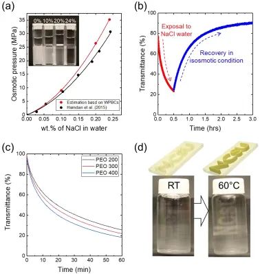
We further investigated how the deviation of WG mixing ratio from 6/4 (the point of RI matching) in the PDMS matrix can alter the optical properties of the composite. We prepared WPBCs by varying the W/G ratio from 2/8 to 8/2 (w/w, RI ~ 1.36 to 1.44). The volume ratio of PDMS to WG was 9/1. The composite exhibited nearly 100 % transmittance at the mixing ratio of W/G= 4/6 at 650 nm. However, a small change (~ 1 wt.%) in the mixing ratio resulted in dramatic decrease in the transmittance from T = 100 % to T = 45 % as shown in Figure 5.1(c) (see also Figure C2 in Appendix C). This agrees with the expression for transmittance of a material by Beer-Lambert law.
71 dyes absorb, and light of other wavelengths pass through without the attenuation (Figure C3 in Appendix C). In the case of Fluorescein solution, the WPBC can emit strong luminescence under a UV lamp (Figure C4 in Appendix C).
Figure 5.1. Fabrication and photographs of WG/PDMS biphasic composites (WPBCs) (a) A schematic representing the fabrication of WPBCs. Water and glycerol (WG) mixture is added to
sheared PDMS precursor. The PDMS emulsion is then molded and heated at 85 °C for thermal crosslinking. (b) A block of a PDMS composite with 30 vol.% of water/glycerol (4/6 : v/v). The
composite is optically transparent and the letters behind the composite are clearly shown. (c) Transmittance of the PDMC composites containing 10 vol.% water/glycerol droplets by varying
water/glycerol mixing ratio. The transmittance values were obtained at a fixed optical wavelength (650 nm) and optical path length (1.0 cm). (d) PDMS composites with dye dissolved
72 5.3.2. Principles of PDMS/WG composite transmittance changes triggered by osmotic pressure
difference
73 Figure 5.2. Optical response of WPBCs to osmotic pressure when present in a water medium. (a) A WPBC immersed in W/G = 4/6 mixture (same as the droplet composition). The WG droplets
in the PDMS composite remain invisible and the WPBC remains transparent. (b) A WPBC immersed in pure water for 30 sec. The WPBC swells with water as the water diffuses molecularly from the water medium to the droplets. Due to the introduction of additional water,
74 5.3.3. Characterization of optical property of WPBCs exposed to WG immersion media
To evaluate the mechanisms proposed above, the swelling ratio and transmittance of WPBCs (30 vol.% of WG droplets) were systematically investigated by changing the ratio of W/G from 4/6 to 10/0 in an immersion bath (Figure 5.3(a)). As time passed, all WPBCs swelled with water except for the case of 4/6 (= W/G) mixing ratio. A decrease in the amount of glycerol in the immersion bath resulted in higher swelling rates due to larger chemical potential differences. On the other hand, the WPBC immersed in an isotonic liquid (W/G = 4/6) did not show any significant swelling behavior.
We measured the transmittance of the WPBCs at a fixed wavelength ~ 650 nm after immersion in several WG ratio mixtures (Figure 5.3(b)). Except for the composite exposed to WG 6/4 bath (isotonic condition), all WPBCs’ transmittances decreased with time. The transmittance
and the swelling ratio values obtained from different WG baths and time could be fitted with a single line (Figure 5.3(c)). As the composite swells with water, the transmittance decreases. The results imply that the transmittance of the composite is directly correlated to the swelling ratio, which is triggered by the chemical potential difference.