OPTIMISED INTELLIGENT TILT CONTROLLER SCHEME USING GENETIC ALGORITHMS
H.Zamzuri1A.C.Zolotas R.M.Goodall
Control Systems Group,
Department of Electronic and Electrical Engineering, Loughborough University, Ashby Road, Loughborough,
LE11 3TU, UK
Abstract:
This paper presents work on a fuzzy control design for improving the performance of tilting trains with local-per vehicle control, i.e. without employing precedence control. An optimisation procedure using Genetic Algorithms was employed to determine both the best fuzzy output membership function and best PID controller parameters. The objective function for the GA procedure was based on a performance index combining the system response on curved and straight track. Simulation results illustrate the effectiveness of the scheme compared to the conventional nulling-tilt approach.
Keywords: tilt control, fuzzy control, genetic algorithms, intelligent control, tilting trains
1. INTRODUCTION
High-speed trains effectively reduce journey times and the way to achieve this is either to develop new infrastructure that maximizes train speeds or to use existing infrastructure with tilting train vehicles. The former solution can prove rather expensive and usually incorporates issues related to the surrounding environment. The latter solu-tion follows a rather straightforward concept, i.e. by leaning the vehicle body inwards on curved sections of the track to reduce the lateral accelera-tion of passengers thereby enabling higher vehicle speeds.
Early tilt systems used local feedback control from a lateral accelerometer mounted on the body of the vehicle. However, it proved difficult to achieve fast response on curve transitions with-out suffering a substantial ride quality degrada-tion on straight track. Current tilting train tech-nology utilise ’precedence’ tilt control strategies
1 corresponding author email:[email protected]
(Goodall, 1999). In this scheme a bogie-mounted accelerometer is used to develop a tilt command signal by measuring the curving acceleration on a non-tilting part of the vehicle. However, because the accelerometer also measures higher frequency movements associated with lateral track irregu-larities, it is necessary to filter the signal. This filtering action (time delay) creates a detrimental performance on the transition from the straight track to the curve section. The usual solution is to use the accelerometer signal from the vehicle in front to provide “precedence”, carefully designed so that the delay introduced by the filter com-pensates for the preview time corresponding to a vehicle length.
Vehicle body
Vehicle bogie
Wheelset
c.o.g
c.o.g kaz
Rail level yv
θv
hg1
hg2
krz crz
ksz
csy
ksy
d1
d2
cpz
kpz
kpy
cpy
kvr
h1
h2
h3
θb
yb
yo δa
θo+ + + +
+
+
Fig. 1. End-view of the vehicle model
combining both the curved-track and straight-track response of the vehicle.
2. VEHICLE MODELING
The mathematical model used for analysis and control design is based upon the end-view of a railway vehicle, to incorporate both the lat-eral and roll degrees of freedom for both the body and the bogie structures. A pair of air-springs represents the secondary suspension, while the primary suspension is modelled via pairs of parallel spring/damper combinations. The stiff-ness/damping of an anti-roll bar connected be-tween the body and the bogie is also included. Ac-tive tilting is provided by using an ‘acAc-tive anti-roll bar’ (Pearsonet al., 1998), see Figure 1. Note that the system is highly complex and characterised by a significant coupling between the lateral and roll motion, and the dynamic modes which result are often referred to as the “sway modes”. Details on the mathematical description can be found in (Zolotas and Goodall, 2000).
3. PERFORMANCE ASSESSMENT
Two main design criteria are concerned with tilt-ing trains: (i) providtilt-ing a fast response on curved track (deterministic criterion), (ii) maintain a good ride quality in response to track irregularities on straight track (stochastic criterion). The pa-per employs the pa-performance assessment approach proposed in (Zolotaset al., 2000).
The assessment of the curve transition is based upon the idea of “ideal tilting”, i.e. where the tilt action follows the specified tilt compensation in an ideal manner according to the maximum tilt angle and cant deficiency compensation fac-tor. Deviations from the “ideal tilting” response quantifies the additional dynamic effects which are caused by the suspension/controller dynamics on the transitions to and from the curves, and provides an objective measure which can be used
offline GA tuning
Track
Suspension roll
measured cant deficiency 1 k
effective cant deficiency for 60 % tilt compensation
2 k Error (e)
u'' PID with Fuzzy Correction Controller (GA)
Fuzzy correction
+
Vehicle model
−1 g-1
lateral accel. PID
conventional
Body roll gyroscope signal
u' pid output
θv gyro
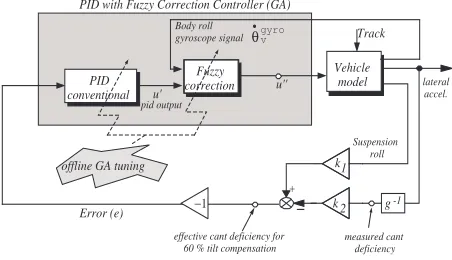
Fig. 2. PID with Fuzzy Correction (with offline GA optimisation)
to compare different strategies (see Appendix A). Note that the calculation of PCT factors is also
included in this stage.
For the straight track case the ‘rule-of-thumb’ which is currently followed by designersis to allow the degradation of the lateral ride quality of the tilting train by no more than a specified margin compared with the non-tilting vehicle, a typical
value being 7.5%. It is essential, for assessing the
tilt controller performance, this comparison to be made at the higher (tilting) speed.
4. FUZZY CONTROL DESIGN
The control design objective is to provide a fast response on curved track while minimizing track irregularities on straight track segments. The con-trol approach followed in this paper involves the design of a conventional PID controller to give a fast curve transition performance and then a fuzzy correction mechanism which improves stability (minimise overshoots and prevent critical oscilla-tions) in the overall system. The PID controller is driven by the effective cant deficiency signal and thus guarantees the appropriate tilt compensation on steady curve (i.e. 60% in this case). Moreover, the output signal from the PID is fed to the fuzzy correction block to further accommodate for curve transition and straight track performance. The body roll rate is the additional decision making variable input to the fuzzy correction block. The control scheme can be seen in Figure 2.
The design of the controller can be divided into three stages :
(1) conventional PID to give fast response on curve track
(2) fuzzy correction aimed at minimizing straight track irregularities and preventing large over-shoot and oscillations on the curved track (3) further tuning if necessary (the GA-tuning
−0.2 0 0.2 0
0.2 0.4 0.6 0.8 1
output from PID/ Roll Rate
Degree of membership
Neg Zero Pos
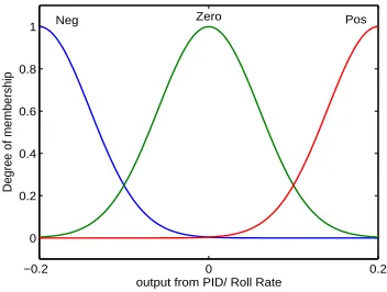
Fig. 3. output from PID (u’) and Roll gyro ( ˙θgyro
v )
-0.27 -0.189 -0.135 0 0.135 0.189 0.27 0
1
Fuzzy Correction output (u'')
Degree of membership
TiltAclkwM TiltAclkwm NoChange TiltClkwm TiltClkwM
Fig. 4. Output controller u”
In the first instance the PID can be tuned using the well known Ziegler-Nichols method (Astrom and Hagglund, 1995). The parameters are chosen to give a fast response on curved track subject to guaranteeing stability.
For the fuzzy correction mechanism, both inputs shown in Figure 3 consist of three equally distrib-uted gaussian Membership Functions with 50% overlap for each signal. Figure 4 shows the fuzzy correction outputu”consisting of trapezoidal and triangle membership functions. Furthermore, the
Center of Area (COA) defuzzification procedure
with well known max-min inference method was used.
The linguistic variables for each membership func-tions represent the condition for each value. For example, the PID outputu’is represented by the linguistic variables Neg, Zero and Pos. For the body roll gyro input ˙θgyro
v , the linguistic variable
are also Neg, Pos and zero, while for the fuzzy correction outputu”, the linguistic variables rep-resent the tilting direction of the car body astilt
the car body clockwise maximum represented by
TiltClkwM, tilt car body medium anticlockwise
represented byTiltAclkwmetc. Clockwise and An-ticlockwise characterize the direction of tilt based on the curve direction (i.e. inwards and outwards of the curve respectively). Note that the mem-bership function ranges were chosen to represent typical required operating ranges for the current
application of tilt. The development of fuzzy rules was based on:
• stabilizing the system:
if u’ ischanging fastand theθ˙gyro
v iszero
thenapply maximum tilt effort u”
• preventing overshoot and oscillation.
if u’ changes and θ˙gyrov changes then
maintain medium till effort u”
Detail on the rules can be further seen in Table 1,
Table 1. PID-Fuzzy Correction Rule Base
˙
θgyrov /u′ Neg Zero Pos
Neg TiltClkwm TiltClkwm TiltClkwM
zero TiltAclkwM NoChange TiltClkwM
Pos TiltAclkwM TiltAclkwm TiltAclkwm
5. GENETIC ALGORITHMS TUNING OPTIMISATION
The main difficulty of the above scheme is primar-ily the choice of of the membership function profile and also the PID controller parameters. These are based on the experience of the designer and can be time-consuming.
Genetic Algorithms is stochastic search tech-niques drawing inspiration from the principles of natural evaluation and genetic laws (Holland, 1998) that operate without the knowledge of the task domain and utilize only the fitness of evalu-ated individuals. In general, there are three basic operators of a GA: (i) reproduction (ii) crossover and (iii) mutation.
In this paper, we utilise eight real-coded GA variables to optimize the PID parameters (KP, KD and KI), and the position and width of the
output fuzzy membership functions (see Figure 2 offline GA). The upper and lower limits on the parameters are established based on the control scheme proposed in (Zamzuri et al., 2005). The initial choice of the parameters and the limits clearly reduce the computational time associated.
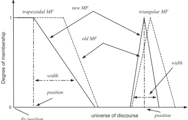
In this study only the output membership func-tion has been used for the optimisafunc-tion process. Figure 4 presents the output membership function which consists of three triangular membership functions and two trapezoidal membership func-tions located at each end of the fuzzy set (from (Zamzuri et al., 2005)). Figure 5 illustrates the concept of coding the membership functions. The genetic algorithm seeks the optimal profile (based on the position and width of the membership functions), except for the zero position of MF
NoChange and also the end limits of (TiltClkwM
0 1
universe of discourse
Degree of membership
triangular MF trapezoidal MF new MF
old MF
position
width
width
fix position position
Fig. 5. Tuning of position and width of member-ship functions
The overall performance index incorporates two terms, i.e. both minimizing the curved track re-sponse error from the ideal case (deterministic) and minimizing the influence of straight track ir-regularities (stochastic). In particular the integral time of absolute error index, (ITAE) (Astrom and Hagglund, 1995), was employed for both terms defined as
IT AE=
Z t
0
t|θerr|(t)dt (1)
where
θerr=θECDaktif −θECDpassive (2)
and
θ(ECDactv)= effective cant deficiency of active system (with control)
θ(ECDpassv) = effective cant deficiency of passive
sys-tem (no control)
The ITAE index limits large initial overshoots and introduces stricter minimisation as time pro-gresses, thus it is expected to offer an advantage in improving the tilt performance. Moreover, the objective function for the GA tuning procedure is given by
f =w1
max(t)
X
t=0
IT AE(det)+w2
max(t)
X
t=0
IT AE(stoch)
(3)
variables w1 and w2 represent the
(complemen-tary) weighting factors of the deterministic and stochastic profiles respectively (w1+w2= 1). Note
the incorporation of both deterministic track and stochastic track for proper minimisation, and thus proper tilt action improvement.
6. SIMULATIONS
The Genetic Algorithms procedure was simulated for 100 generations on a randomly initialized
pop-−0.27 0 0.27
0 1
Fuzzy Correction Output u’’
Degree of membership
TiltAclkwM TiltAclkwm NoChange TiltClkwm TiltClkwM
Fig. 6. Output membership function without (dot-ted) and with GA optimisation (solid)
0 200 400 600 800 1000 1200
−1 −0.5 0 0.5 1 1.5 2
Lateral acceleration @ 210 km/h
lateral accelaration (m/s
2)
lenght (m)
PI conv. PID Fuzzy PID Fuzzy (GA) Ideal
Fig. 7. Body Lateral acceleration
ulation of 10 solutions. The GA performance use roulette wheel selection method with probability crossover and mutation rate of 0.9 and 0.125 re-spectively, and with weighting factors w1 and w2
of 0.2 and 0.8 respectively.
The system was simulated at a speed of 210 km/h with 1000 m curved radius and 6o cant angle (the
track profile included 145 m transition length at each end of the curve). For proper comparison, the system was simulated using using three con-trollers (i) PID with Fuzzy Correction mechanism (manually tuned (Zamzuri et al., 2005)) (ii) The same controller using GA-tuning and (iii) nulling PI conventional controller. Figure 6 shows the op-timal output fuzzy membership function for both the manually tuned and GA-tuned schemes. Table 2 presents the PID parameter values using the Ziegler-Nichols tuning method (manual-tuning) and the GA-tuning method.
Table 2. Manual Ziegler-Nichols vs GA tuning for the PID controller
PID params Ziegler-Nichols Genetic Alg.
KP 0.19 0.31
KI 1.15 1.60
KD 0.03 0.04
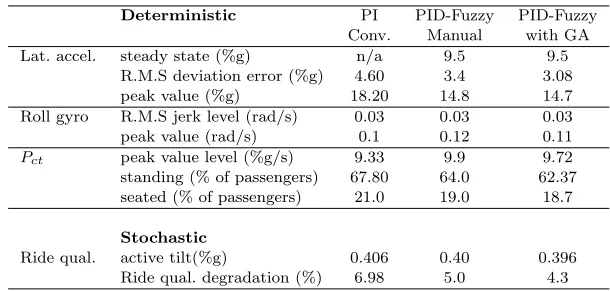
Table 3. Performance assessment results
Deterministic PI PID-Fuzzy PID-Fuzzy
Conv. Manual with GA
Lat. accel. steady state (%g) n/a 9.5 9.5
R.M.S deviation error (%g) 4.60 3.4 3.08
peak value (%g) 18.20 14.8 14.7
Roll gyro R.M.S jerk level (rad/s) 0.03 0.03 0.03
peak value (rad/s) 0.1 0.12 0.11
Pct peak value level (%g/s) 9.33 9.9 9.72
standing (% of passengers) 67.80 64.0 62.37
seated (% of passengers) 21.0 19.0 18.7
Stochastic
Ride qual. active tilt(%g) 0.406 0.40 0.396
Ride qual. degradation (%) 6.98 5.0 4.3
0 200 400 600 800 1000 1200 −1
0 1 2 3 4 5 6 7 8 9
length (m) Body roll angle (actual tilt)
angle (deg)
relative to track
PI conv. PID Fuzzy (GA) PID Fuzzy ideal tilt
Fig. 8. Body Roll Angle
7. PERFORMANCES ANALYSIS
This section presents the performance assessment, based on the procedure discussed in Section 3, of the discussed fuzzy schemes (PID-Fuzzy manual and PID-Fuzzy with GA tuning) together with a baseline conventional PI nulling controller. The associated results are shown in Table 3. Both PID-fuzzy correction control schemes provide a much better performance compared to the conven-tional controller. Although the PID-Fuzzy with GA tuning scheme offers a small (but noticeable) improvement compared to the PID-Fuzzy manual, it is easier to design for more accurate results. Note that the straight track ride quality of the non-tilting vehicle at 210 km/h is 0.381%g.
8. CONCLUSION
The paper reveals the potential of using a PID-Fuzzy with GA tuning control solution in a nulling-tilt control framework for improving the performance of local-per-vehicle tilt. Both fuzzy control schemes (manual-tuned and GA-tuned) provided substantial improvement of the tilt per-formance compared to the conventional nulling controller. The advantage of using the GA-tuned solution is the more straightforward setup of the output membership function and PID controller parameters via the chosen performance index. Fu-ture work will investigate on multi-objective
Ge-netic Algorithm (MOGA) solutions for both the membership functions and controller parameters.
9. REFERENCES
Astrom, K. J. and T. Hagglund (1995). PID
controllers: Theory, Design, and Tuning2nd
Ed.. Instr. Society of America.
Goodall, R. M. (1999). Tilting trains and beyond -the future for active railway suspensions: Part 1 improving passenger comfort. Computing
and Control Enginerring Journal10(4), 153–
160.
Holland, John H. (1998). Adaptation in natural
and artificial systems. MIT Press. USA.
Pearson, J. T., R. M. Goodall and I. Pratt (1998). Control system studies of an active anti-roll bar tilt system for railway vehicles.
Proceed-ing, Inst of Mechanical Engineering212 Part
F, 43–60.
Zamzuri, H., A. C. Zolotas and R. M. Goodall (2005). Intelligent control approaches for tilt-ing railway vehicles. In:19th IAVSD
Sympo-sium 2005. Milan, Itali.
Zolotas, A. C. (2002). Advanced Control Strate-gies for Tilting Trains. PhD thesis. Loughbor-ough University, UK.
Zolotas, A. C., R. M. Goodall and J. Evans (2000). Assesment of the performance of tilt system controllers. In: The Railway Conference at
Railtex 2000. NEC Birmingham, UK. pp. 21–
23.
Zolotas, A.C. and R.M. Goodall (2000). Advanced Control Strategies for tilting railway vehicles.
Appendix A. ASSESSMENT APPROACH xxxx xxxxxxxxx xxxxx xxxxx xxxxx xxxxx xxxxxx xxxxxx xxxxxx xxxxxx xxxxxx xxxxxx xxxxxxxxxxxxx xxxxxxx xxxxxxx xxxxxxx xxxxxxx xxxxxxx xxxxxxxxxxxx xxxxx xxxxx xxxxx xxxxxxxxxxxxx xxxxxxxx xxxxxxxx xxxxxxxx xxxxxxxx xxxxxxxx xxxxxxxx xxxxxxxx xxxxxxxx xxxxxx xxxxxx xxxxxxxxxxx xxxxx xxxxx xxxxx xxx x x x x x x x x x x x x x x x x x x x x x x x x x x x x x x x x x x x x x x x x x x x x x x x x x x x x x x x x x x x x x x x x x x x x x x x x x x x x x x 1sec 3.6sec lateral acceleration time x x x x x x x x x x x x x x x x x x x x x x x x x x x x x x x x x x x x x x x x x x x x x x x x x x x x x x x x x x x x x x x x x x x x x x x x x x x x x x x x x x x x x x x x x x x x x x x x x x x x x x x x x x x x x x x x x x x x x x x x x x x x x x x x x x x x x x x x x x x x x x x x x x x x x x x x x x x x x x x x x x x x x x x x x x x x x x x x x x x x x x x x x x x x x x x x x x x x x
Field of calculation of
absolute roll velocity time xxxxx xxxxx xxxxxxxx xxx xxxxxxx xxxxxxx xxxxxxx xxxxxxx xxxxxxx xxxxxxx xxxxxxx xxxxxxx xxxxxxx xxxxxxx xxxxxxx xxxxxxx xxxxxxx xxxxxxx xxxxxxx xxxxxxx xxxxxxx xxxxxxx xxxx xxxx xxxxxxxxxx xxxxxx xxxxxx xxxxxx xxxxxxxxx xxx
Field of calculation of y - ym
m |.. .. |
i RMS( )
θ − θ m m
|. |
i .
RMS( )
1sec xxxx xxxx xxxx xxxx xxxx xxxxxxxxxx 3.6sec x x x x x x x x x x x x x x x x x x x x x x x x x x x x x x x x x x x x x x x x x x x x x x x x x x x x x x x x x x x x xxxx xxxx xxxx xxxx xxxx xxxx xxxx xxxx xxxx xxxx xxxx xxxx xxxx xxxx xxxx xxxx xxxx xxxx xxxx xxxxxxx xxx xxxxxxxxxxxxxxx xxxxxxxxxxxxxxx xxxxxxxxxxxxxxx xxxxxxxxxxxxxxx xxxxxxxxxxxxxxx
Fig. A.1. “Ideal Tilting”- Calculation of deviation of actual from ideal responses for acceleration and roll velocity
|y¨m−y¨mi|, the deviation of the actual lateral
ac-celeration y¨m from the ideal lateral acceleration
¨
ymi, in the time interval between 1s before the
start of the curve transition and 3.6s after the end of the transition.
θ˙m−θ˙mi
, the deviation of the actual absolute
roll velocityθ¨mfrom the ideal absolute roll velocity
¨
θmi, in the time interval between 1s before the