University of Windsor University of Windsor
Scholarship at UWindsor
Scholarship at UWindsor
Electronic Theses and Dissertations Theses, Dissertations, and Major Papers
2012
EXPERIMENTAL INVESTIGATION OF AUTOMATIC
EXPERIMENTAL INVESTIGATION OF AUTOMATIC
TRANSMISSION FLUID (ATF) IN AN AIR COOLED MINICHANNEL
TRANSMISSION FLUID (ATF) IN AN AIR COOLED MINICHANNEL
HEAT EXCHANGER
HEAT EXCHANGER
MD ABDUL QUAIYUM University of Windsor
Follow this and additional works at: https://scholar.uwindsor.ca/etd
Recommended Citation Recommended Citation
QUAIYUM, MD ABDUL, "EXPERIMENTAL INVESTIGATION OF AUTOMATIC TRANSMISSION FLUID (ATF) IN AN AIR COOLED MINICHANNEL HEAT EXCHANGER" (2012). Electronic Theses and Dissertations. 371. https://scholar.uwindsor.ca/etd/371
This online database contains the full-text of PhD dissertations and Masters’ theses of University of Windsor students from 1954 forward. These documents are made available for personal study and research purposes only, in accordance with the Canadian Copyright Act and the Creative Commons license—CC BY-NC-ND (Attribution, Non-Commercial, No Derivative Works). Under this license, works must always be attributed to the copyright holder (original author), cannot be used for any commercial purposes, and may not be altered. Any other use would require the permission of the copyright holder. Students may inquire about withdrawing their dissertation and/or thesis from this database. For additional inquiries, please contact the repository administrator via email
(ATF) IN AN AIR COOLED MINICHANNEL HEAT EXCHANGER
by
Md Abdul Quaiyum
A Thesis
Submitted to the Faculty of Graduate Studies
through Mechanical, Automotive, and Materials Engineering in Partial Fulfillment of the Requirements for
the Degree of Master of Science at the University of Windsor
Windsor, Ontario, Canada
2012
EXPERIMENTAL INVESTIGATION OF AUTOMATIC TRANSMISSION FLUID
(ATF) IN AN AIR COOLED MINICHANNEL HEAT EXCHANGER
by
Md Abdul Quaiyum
APPROVED BY:
______________________________________________ Dr. Paul Henshaw
Department of Civil and Environmental Engineering
______________________________________________ Dr. Daniela Pusca
Department of Mechanical, Automotive, and Materials Engineering
______________________________________________ Dr. Amir Fartaj, Advisor
Department of Mechanical, Automotive, and Materials Engineering
______________________________________________ Dr. Bill Zhou, Chair of Defense
Department of Mechanical, Automotive, and Materials Engineering
DECLARATION OF ORIGINALITY
I hereby certify that I am the sole author of this thesis and that no part of this thesis has
been published or submitted for publication.
I certify that, to the best of my knowledge, my thesis does not infringe upon anyone’s
copyright nor violate any proprietary rights and that any ideas, techniques, quotations, or
any other material from the work of other people included in my thesis, published or
otherwise, are fully acknowledged in accordance with the standard referencing practices.
Furthermore, to the extent that I have included copyrighted material that surpasses the
bounds of fair dealing within the meaning of the Canada Copyright Act, I certify that I
have obtained a written permission from the copyright owner(s) to include such
material(s) in my thesis and have included copies of such copyright clearances to my
appendix.
I declare that this is a true copy of my thesis, including any final revisions, as approved
by my thesis committee and the Graduate Studies office, and that this thesis has not been
ABSTRACT
Narrow-channels have been subjected to diversified research and application interests
due to miniaturized geometry and lightweight, superior heat transfer characteristics,
and better energy efficiency. Automatic Transmission Fluid (ATF) cooling is one of
the most important challenges in the automotive industry due to its changing
thermo-physical properties as a result of temperature and frictional environment which exist,
inside the transmission. In this study, efforts have been accumulated to justify the
suitability of Minichannel Heat Exchanger (MICHX) application in characterizing
ATF cooling and its flow behaviours.
An experimental investigation has been conducted with the aid of a well-equipped
closed loop thermal wind tunnel, which uses a wavy finned MICHX as the test
specimen. During the experiment, ATF mass flow rates were varied to achieve
Reynolds Number of 3 ≤ ReL ≤ 30. The effects of serpentines on ATF heat transfer
and flow behaviours were investigated in a laminar flow regime. Heat transfer
enhancement was observed due to the serpentine structure. The effects of
dimensionless parameters; such as Reynolds number, Nusselt number, Prandtl
number, Brinkman number, and Ekert number on heat and mass transfer
characteristics were examined. Heat and mass transfer correlations were established
while considering variable property ratio.
The investigation showed promising heat transfer characteristics and good agreement
DEDICATION
Dedicated to-
My beloved Mother who prays day and night,
Who loves me the most,
Experimental Investigation of Automatic Transmission Fluid (ATF) in an Air Cooled Minichannel Heat Exchanger
ACKNOWLEDGEMENTS
First the author is greatly thankful to the Almighty, the Creator and the Sustainer.
The author likes to express his sincere gratitude and appreciation to his advisor Dr. Amir
Fartaj for offering him the opportunity in conducting such a needful research. His diligent
and distinctive guidance, supports, and judicious opinion throughout the research are
gratefully honored. His expert supervision, thoughtful instruction, intellectual academic
input, and incessant inspiration led the author to a successful completion of the research.
The author likes to thankfully recognize the advices from the committee members; Dr.
Paul Henshaw and Dr. Daniela Pusca for their most valuable suggestions and comments
which made the write-up more readable and informative.
The author offers his deep appreciation and gratefulness to Mr. Andy Jenner for his
cordial technical supports and sincere efforts in remodeling the experimental setup.
Special thanks and acknowledgements are extended to Ms. Rose Gignac for providing the
author with friendly secretarial supports throughout the program. Warm
acknowledgement goes to Ms. Barb Denomey for her cordial assistance in all respect
during the program in the Department of Mechanical, Automotive, and Materials
Engineering.
The author gratefully recognizes the advice from Dr. Mesbah-ul Ghani Khan. Special
thanks and gratitude are presented to Serena Askar for her sincere efforts in compiling the
write-up and assistance during equipment operation. Continuous efforts, expense of
Fotowat, Mohammed Ismail, Mohammed Saadi, and Mr. Sarbadaman Dasgupta are
inevitably acknowledged.
Lastly, the author likes to express his deep obligation to the Almighty for His blessings
Experimental Investigation of Automatic Transmission Fluid (ATF) in an Air Cooled Minichannel Heat Exchanger
viii TABLE OF CONTENTS
DECLARATION OF ORIGINALITY ... iii
ABSTRACT ... iv
DEDICATION ...v
ACKNOWLEDGEMENTS ... vi
LIST OF TABLES ... xvi
LIST OF FIGURES ... xvii
NOMENCLATURE/ABBREVIATIONS ... xxi
CHAPTER I. INTRODUCTION 1.1 Motivation ...7
1.2 Objectives ...8
II. REVIEW OF LITERATURE 2.1 Heat-Transfer Characteristics at Laminar Flow in Minichannel ..11
2.2 Automatic Transmission Fluid ...12
2.2.1 Transmission Efficiency ...15
2.2.2 Temperature Dependency of ATF ...16
2.2.3 Newtonian and Non-Newtonian Behaviour of ATF ...17
2.2.4 Automatic Transmission Fluid Properties ...18
2.3 Viscous Effect of Liquid on Temperature Variation ...20
2.5 Scope of Current Research ...24
III. DESIGN AND METHODOLOGY 3.1 Key Assumptions ...26
3.2 Bulk Temperature and Thermo-physical Properties of ATF ...27
3.3 Dimensionless Fluid Flow and Heat Transfer Parameters ...29
3.3.1 Reynolds Number (Re) ...29
3.3.2 Prandtl Number (Pr) ...31
3.3.3 Brinkman Number (NBr) ...32
3.3.4 Eckert Number (Ec) ...32
3.3.5 Dean Number (De) ...33
3.3.6 Poiseuille Number (Po) ...34
3.3.7 Nusselt Number (Nu) ...35
3.3.8 Péclet Number (Pe) ...37
3.4 Heat Transfer Calculation ...38
3.4.1 Heat Transfer Rate and Heat Balance ...38
3.4.2 Heat Transfer Coefficient ...39
3.4.3 Thermal Diffusivity ...40
3.5 Pressure Drop ...41
3.5.1 Friction Factor (f) ...41
Experimental Investigation of Automatic Transmission Fluid (ATF) in an Air Cooled Minichannel Heat Exchanger
3.6 Pipe Flow ...44
3.6.1 Pressure Drop in a Straight Tube ...46
3.6.2 Pressure Drop in a Curved Tube ...47
3.6.3 ATF Flow Rate in Laminar Regime ...50
3.7 Air Flow ...51
3.7.1 Air Mass Flow Rate ...51
3.7.2 Air-Side Reynolds Number (Rea) ...52
3.8 Air-side Heat Transfer Calculation ...53
3.8.1 Log Mean Temperature Difference (LMTD) ...53
3.8.2 Overall Thermal Resistance ...55
3.8.3 Air-Side Heat Transfer Coefficient (ha) ...57
3.9 Heat Exchanger Performance ...59
3.9.1 Heat Exchanger Number of Transfer Unit (NTU) ...59
3.9.2 Effectiveness (ε) ...60
IV. EXPERIMENTAL SETUP: INSTRUMENTATION AND MANAGEMENT 4.1.1 Reservoir Tank ...64
4.1.2 Gear Pump with Frequency-Controlled Motor ...65
4.1.3 Recirculation Pump ...67
4.1.5 Chiller ...69
4.1.6 Needle Gauges for Temperature and Pressure Monitor ...69
4.1.7 Pressure Transducers (PTD) ...70
4.1.8 Resistance Temperature Detector (RTD) ...72
4.1.9 Micro-Filter ...74
4.1.10 Flow Meters ...74
4.2 Air Handling System ...76
4.2.1 Integrated Closed Loop Thermal Wind Tunnel ...77
4.2.2 Test Chamber ...78
4.2.3 Air Temperature Measurement ...79
4.2.4 Surface Temperature Measurement ...80
4.2.5 Air Pressure Measurement ...81
4.3 Automated Data Acquisition (DAQ) System ...83
4.3.1 DC Voltage Supply Unit and Secondary Terminal Block ...86
4.3.2 SCXI Signal Conditioning ...86
4.3.3 Flow-Kinetic (FKT) ...88
4.3.4 LabView Data Acquisition System ...89
4.4 Minichannel Heat Exchanger ...89
Experimental Investigation of Automatic Transmission Fluid (ATF) in an Air Cooled Minichannel Heat Exchanger
4.6 Experimental Methods ...93
V. RESULTS AND DISCUSSIONS 5.1 ATF Properties ...97
5.1.1 Viscosity ...97
5.1.2 Density ...100
5.1.3 ATF Mass Flow Rate ...100
5.2 Heat transfer characteristics ...103
5.2.1 Inlet-Outlet Temperature Difference and ReL ...103
5.2.2 Heat Balance ...104
5.2.3 Heat Transfer Rate ...105
5.2.4 Normalized Heat Transfer and Liquid Reynolds Number ...106
5.2.5 Effect of ReL on Non-Dimensional Temperature ...107
5.2.6 Convective Heat Transfer Coefficient ...111
5.2.7 Effect of ReL on Nusselt Number ...112
5.3 Non-Dimensional Numbers ...117
5.3.1Dean Number (De) ...117
5.3.2 Eckert Number ...120
5.3.3 Brinkman Nunber ...122
5.4 Air-Side Heat Transfer ...125
5.4.2 Air-Side Nusselt Number ...127
5.5 Pressure Drops ...128
5.5.1 Pressure Drop Analysis in MICHX ...128
5.5.2 Effect of ReL Over Pressure-Drop Mass-Flux (G) Ratio ...132
5.5.3 Effect of Temperature on Pressure Drop (∆P) ...134
5.5.4 Friction Factor ...135
5.6 Heat Exchanger Performance ...138
5.6.1 Effectiveness ...138
5.6.2 Number of Transfer Unit (NTU) ...140
5.6.3 Heat Exchanger Conductance (UA) ...144
VI. CONCLUSIONS AND RECOMMENDATIONS 6.1 Conclusions...146
6.2 Recommendations ...150
VII. APPENDICES APPENDIX A INSTRUMENT CALIBRATION AND SPECIFICATION A.1 General Overview ...152
A.1.1 Digital Flow Meter (DFM) ...152
A.1.2 Impeller Flow Meter (IFM) ...153
A.2.1 Pressure Transducer (PTD) ...154
Experimental Investigation of Automatic Transmission Fluid (ATF) in an Air Cooled Minichannel Heat Exchanger
A.2.3 Liquid outlet Pressure Transducer ...155
A.2.4 Gas Differential Pressure Transducer (DPTD) ...156
A.2.5 Test Chamber Middle Location DPTD ...157
A.2.6 Test Chamber Top Location DPTD ...158
A.3.1Thermal Conductivity ...160
A.3.2 Specific Heat Capacity (Cp) ...160
APPENDIX B UNCERTAINTY ANALYSIS ...162
B.1 Bias...163
B.2 Precision ...163
B.3 Repeatability ...163
B.4 Uncertainty in Independent Variables ...164
B.5 Uncertainty in Dependent Variables ...164
B.6 Uncertainty in Thermo-physical properties ...165
B.6.1 Uncertainty in the Liquid Side Temperatures ...165
B.6.2 Bulk Temperature ...165
B.6.3 Uncertainty in the Liquid Side Density...166
B.6.4 Uncertainty in the Liquid Side Specific Heat ...166
B.6.5 Uncertainty Related to the Liquid Mass Flow Rate ...166
B.6.6 Uncertainty in the Liquid Reynolds Number ...167
B.7.1 Uncertainty in the Airside Temperatures ...168
B.7.2 Uncertainty in the Air Reynolds Number ...170
B.7.3 Uncertainty in the Air Heat Transfer Rate ...171
B.8 Uncertainty in the Average Heat Transfer Rate ...171
B.9 Uncertainty in Effectiveness ...172
B.10 Uncertainty in the Heat Capacity Rate Ratio ...172
B.11Example of Calculating Uncertainty ...173
B.11.1 Uncertainty in ATF Reynolds Number ...173
B.11.2 Uncertainty in ATF Prandtl Number ...174
B.11.3 Uncertainty in ATF Nusselt Number ...174
B.12 Uncertainty of the instrument and devices used ...175
APPENDIX C EXPERIMENTAL DATA ...178
REFERENCES ...202
Experimental Investigation of Automatic Transmission Fluid (ATF) in an Air Cooled Minichannel Heat Exchanger
LIST OF TABLES
TABLE-2.1:AUTOMATIC TRANSMISSION FLUID PROPERTIES ... 18
TABLE-5.1:UNCERTAINTY IN VISCOSITY MEASUREMENT ... 99
TABLE A.1:DIGITAL FLOW METER (DFM) ... 152
TABLE A.2:IMPELLER FLOW METER SPECIFICATION... 153
TABLE A.3:LIQUID INLET PRESSURE TRANSDUCER SPECIFICATION ... 154
TABLE A.4:LIQUID OUTLET PRESSURE TRANSDUCER SPECIFICATION ... 156
TABLE A.5:TEST CHAMBER MIDDLE LOCATION DPTDSPECIFICATION ... 157
LIST OF FIGURES
FIGURE-2.1:WORKING TEMPERATURE OF ATF AND TRANSMISSION LIFE ... 14
FIGURE-3.1:HYDRODYNAMICALLY DEVELOPING AND DEVELOPED BOUNDARY LAYER .. 45
FIGURE-4.1:SCHEMATIC DIAGRAM OF THE INSTRUMENTAL NETWORK ... 63
FIGURE-4.2:POSITIVE DISPLACEMENT GEAR PUMP ... 66
FIGURE-4.3:RECIRCULATION PUMP AND HEATER ELEMENT ... 68
FIGURE-4.4:WHEATSTONE BRIDGE CIRCUIT ... 70
FIGURE-4.5:PRESSURE TRANSDUCERS (INLET AND OUTLET) AND THE TEST CHAMBER ... 71
FIGURE-4.6:PRESSURE TRANSDUCER (PTD)&RESISTANCE TEMPERATURE DETECTOR (RTD) ... 71
FIGURE-4.7:WHEATSTONE BRIDGE CIRCUIT FOR RTDS... 72
FIGURE-4.8:DIGITAL FLOW METER (DFM)... 75
FIGURE-4.9:IMPELLER FLOW METER ... 76
FIGURE-4.10:WINDS TUNNEL WITH BLOWER MOTOR ... 77
FIGURE-4.11:TEST CHAMBER AND THE HEAT EXCHANGER ... 78
FIGURE-4.12:OUTLET AND INLET THERMOCOUPLE GRIDS ... 79
FIGURE-4.13:PLACEMENT OF TCPROBE FOR SURFACE TEMPERATURE MEASUREMENT . 81 FIGURE-4.14:DIFFERENTIAL PRESSURE TRANSDUCERS (DPTD) ... 82
FIGURE-4.15:DIFFERENTIAL PRESSURE TRANSDUCER WORKING DIAGRAM ... 82
Experimental Investigation of Automatic Transmission Fluid (ATF) in an Air Cooled Minichannel Heat Exchanger
FIGURE-4.17:FLOW DIAGRAM FOR THE DAQSYSTEM DEVICE CONNECTIVITY ... 85
FIGURE-4.18:TERMINAL BLOCK,VDC AND THE SIGNAL CONDITIONER ... 85
FIGURE-4.19:FLOW KINETICS AND PITOT STATIC TUBE CONFIGURATION ... 88
FIGURE-4.20:HEAT EXCHANGER DIMENSIONS ... 90
FIGURE-4.21:HEAT EXCHANGER SLAB AND THE MANIFOLD ... 90
FIGURE-4.22:OPERATING CONDITIONS AND EXPERIMENTAL SET POINTS ... 92
FIGURE-5.1:VISCOSITY VARIATION WITH TEMPERATURE CHANGE... 98
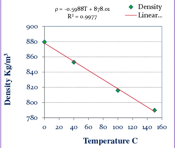
FIGURE-5.2:DENSITY VARIATION WITH TEMPERATURE CHANGE... 100
FIGURE-5.3:EFFECT OF VISCOSITY ON MASS FLOW RATE ... 102
FIGURE-5.4:ATFINLET-OUTLET TEMPERATURE DIFFERENCE,∆TOC ... 104
FIGURE-5.5:HEAT BALANCE VS LIQUID REYNOLDS NUMBER ... 105
FIGURE-5.6:ATFHEAT TRANSFER RATE WITH RESPECT TO ATFREYNOLDS NUMBER . 106 FIGURE-5.7:EFFECT OF LIQUID REL ON NORMALIZED HEAT TRANSFER ... 107
FIGURE-5.8:EFFECT OF ATFREYNOLDS NUMBER ON DIMENSIONLESS TEMPERATURE . 108 FIGURE-5.9(A):EFFECT OF LIQUID REYNOLDS NUMBER ON LMTD ... 109
FIGURE-5.9(B):EFFECT OF LIQUID REYNOLDS NUMBER ON NON-DIMENSIONAL TEMPERATURES (∆T&LMTD) ... 110
FIGURE-5.10:EFFECT OF ATFRE ON HEAT TRANSFER COEFFICIENT ... 111
FIGURE-5.11:EFFECT OF LIQUID RE ON LIQUID NU ... 113
FIGURE-5.12:EFFECT OF REL AND PRL ON NUSSELT NUMBER (NUL) ... 116
FIGURE-5.13:EFFECT OF DE ON NUSSELT NUMBER,NU ... 118
FIGURE-5.15:EFFECT OF EC ON NUSSELT NUMBER,NUL ... 121
FIGURE-5.16:EFFECT OF MASS FLUX,GON NBR ... 123
FIGURE-5.17:EFFECT OF NBR ON NUSSELT NUMBER,NUL... 124
FIGURE-5.18:EFFECT OF NBR ON NUSSELT NUMBER,NUL... 124
FIGURE-5.19:EFFECT OF AIR-SIDE REA ON AIR HEAT TRANSFER COEFFICIENT,HA ... 126
FIGURE-5.20:EFFECT OF AIR-SIDE REA ON AIR NUSSELT NUMBER NUA ... 127
FIGURE-5.21:EFFECT OF RELON SYSTEM PRESSURE AND THE PRESSURE ALONG THE CHANNEL ONLY ... 130
FIGURE-5.22:EFFECT OF ATFMASS VELOCITY (G)ON PRESSURE ALONG THE CHANNEL ... 131
FIGURE-5.23:EFFECT OF REL ON PRESSURE DROP-MASS VELOCITY RATIO ... 133
FIGURE-5.24:EFFECT OF TEMPERATURE ON NORMALIZED PRESSURE DROPS W. R. T. (∆P/G) ... 134
FIGURE-5.25:RELATION BETWEEN DARCY’S FRICTION FACTOR FD AND THE REL ... 136
FIGURE-5.26:RELATION BETWEEN DARCY’S FRICTION FACTOR FD AND THE REL IN A LOG -LOG PLOT ... 137
FIGURE-5.27:EFFECT OF REA ON EFFECTIVENESS ... 139
FIGURE-5.28:EFFECT OF REL ON EFFECTIVENESS,Ε ... 140
FIGURE-5.29:EFFECT OF REA ON NTU ... 141
FIGURE-5.30:EFFECT OF REL ON NTU ... 141
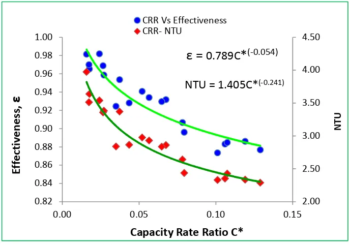
FIGURE-5.31:EFFECT OF Ε-NTUAND HEAT CAPACITY RATE RATIO (CRR),C* ... 142
FIGURE-5.32:Ε-NTU RELATIONS ... 143
Experimental Investigation of Automatic Transmission Fluid (ATF) in an Air Cooled Minichannel Heat Exchanger
FIGURE A.1:DFMCALIBRATION CURVE ... 153
FIGURE A.2:IFMCALIBRATION CURVE ... 154
FIGURE A.3:PTD INLET CALIBRATION DATA AND CURVE ... 155
FIGURE A.4:PTDOUTLET CALIBRATION DATA AND CURVE ... 156
FIGURE A.5:DPTDMIDDLE LOCATION CALIBRATION DATA AND CURVE ... 158
FIGURE A.6:DPTDPITOT STATIC CALIBRATION DATA AND CURVE ... 158
FIGURE A.7:DPTD AT BOTTOM LOCATION CALIBRATION DATA AND CURVE ... 159
FIGURE A.8:THERMAL CONDUCTIVITY VARIATION WITH TEMPERATURE CHANGE ... 160
NOMENCLATURE/ABBREVIATIONS
Cross-Sectional Area of Fluid Flow, (m2)
Total Channel Heat-Transfer Surface Area, (m2)
Minimum Air-Flow Frontal Area, (m2)
Combined Available Air Heat-Transfer Surface Area, (m2)
Specific Heat Capacity, (J/Kg-K)
Liquid Specific Heat Capacity, (J/Kg-K)
Air Specific Heat Capacity, (J/Kg-K)
Hot Fluid Heat Capacity Rate, (J/s-K)
Cold Fluid Heat Capacity Rate, (J/s-K)
Liquid Heat Capacity Rate, (J/s-K)
Air Heat Capacity Rate, (J/s-K)
∗ Capacity Rate Ratio
cP Centi-Poise, Unit of Dynamic Viscosity
cSt Centi-Stroke, Unit of Kinematic Viscosity
Minimum Heat Capacity Rate, (J/s-K)
Channel Diameter, (m)
Dc Serpentine Curvature Diameter, (m)
DT Thermal Diffusivity, (m2/s)
Dh Channel Hydraulic Diameter, (m)
Liquid-Side Channel Hydraulic Diameter, (m)
Air-Side Channel Hydraulic Diameter, (m)
Experimental Investigation of Automatic Transmission Fluid (ATF) in an Air Cooled Minichannel Heat Exchanger
Channel Outside Diameter, (m)
Channel Inside Diameter, (m)
Eckert Number
f Friction Factor
ƒ Darcy’s Friction Factor
ƒ Fanning’s Friction Factor
ƒ Friction Factor Corrected for Temperature with Variable Property Ratio
ƒ Friction Factor at Curvature Part of Channel (Serpentine Part)
ƒ Friction Factor at the Straight Part of the Channel
LMTD Correction Factor for Multi-pass and Cross-flow Heat Exchanger
gc Acceleration Due to Gravity, (m/s2)
G Mass Flux, (kg/m2-s)
Liquid Mass Flux (Mass Flow Rate per Unit Area), (kg/m2-s)
h Heat Transfer Coefficient, (W/m2-K)
ℎ Liquid Heat Transfer Coefficient, (W/m2-K)
ℎ Air Heat Transfer Coefficient, (W/m2-K)
k Thermal Conductivity, (W/m-K)
Thermal Conductivity of Aluminum, (W/m-K)
Thermal Conductivity of Liquid, (W/m-K)
L Channel Length, (m)
La Air Flow Length, (m)
Lhy Hydrodynamic Entrance Length of Liquid, (m)
Mass-Flow Rate, (kg/s)
Liquid Mass-Flow Rate, (kg/s)
Air Mass-Flow Rate, (kg/s)
!" Brinkman Number
!# Nusselt Number
!# Liquid Nusselt Number
!# Air Nusselt Number
!# Nusselt Number Corrected for Temperature with Variable Property Ratio
!# Liquid Nusselt Number Corrected for Temperature with Variable Property
Ratio
!# Nusselt Number at Mean/Bulk Temperature
!#$ Nusselt Number at Wall Temperature
!%& Number of Transfer Unit
P Wetted Perimeter, (m)
'( Dynamic Pressure of Air, (kPa)
' Péclet Number
Po Poiseuille Number
Pr Prandtl Number
') Liquid Prandtl Number
')* Glycol Prandtl Number
P Pressure Drop, (kPa)
+ Heat Transfer Rate, W
Experimental Investigation of Automatic Transmission Fluid (ATF) in an Air Cooled Minichannel Heat Exchanger
+ Air-Side Heat Transfer Rate, W
+ ,* Average Heat Transfer Rate, W
+ Maximum Heat Transfer, W
- Heat Transfer Rate, W
. Radius of Serpentine Curvature, (m)
. Reynolds Number
./ Liquid Reynolds Number
./* Glycol Reynolds Number
./ Air Reynolds Number
./ Critical Reynolds Number
. Liquid-Side Thermal Resistance, (oK/W)
. Air-Side Thermal Resistance, (oK/W)
. Total Thermal Resistance, (oK/W)
.$ Solid Wall Thermal Resistance, (oK/W)
%0 Liquid Inlet Temperature, (
o C)
%1 Liquid Outlet Temperature, (
o C)
%2 Liquid Bulk Temperature, (
o C)
%0 Air Inlet Temperature, (
o C)
%1 Air Outlet Temperature, (
o C)
%2 Air Bulk Temperature, (oC)
% Hot-Fluid Inlet Temperature, (oC)
% Cold-Fluid Inlet Temperature, (oC)
% Cold-Fluid Outlet Temperature, (oC)
%0 Channel inside Wall Temperature, (
o C)
%1 Channel outside Wall Temperature, (
o C)
% Film Temperature, (oC)
% Inlet Temperature, (oC)
%3 Outlet Temperature, (oC)
%2 Bulk Temperature, (oC)
%$ Wall Temperature, (oC)
T Temperature Difference, (oC)
∆% Liquid Temperature Difference, (oC)
∆% Air Temperature Difference, (oC)
∆% Log-Mean-Temperature Difference, (oC)
& Overall Heat Transfer Conductance, (W/oK)
5 Velocity, (m/s)
5 Liquid Velocity, (m/s)
5 Air Velocity, (m/s)
Ṽ Volume Flow Rate through the Channels, (m3/s)
Ṽ Pump Volume Flow Rate, (m3/s)
Experimental Investigation of Automatic Transmission Fluid (ATF) in an Air Cooled Minichannel Heat Exchanger
6$ Wall Shear Stress, (kPa)
α Thermal Diffusivity, (m2/s)
7 Density, (kg/m3)
7 Liquid Density, (kg/m3)
7 Air Density, (kg/m3)
8 Kinematic Viscosity, (centi-Stroke)
B Dynamic Viscosity, (kg/m-s, centi-Poise, (SSU) Saybolt Universal
Seconds)
B Film Dynamic Viscosity, (centi-Poise)
B Liquid Dynamic Viscosity, (centi-Poise)
B Air Dynamic Viscosity, (centi-Poise)
B Dynamic Viscosity of Liquid at Bulk/Mean Temperature, (centi-Poise)
B$ Dynamic Viscosity of Liquid at inside Wall Temperature, (centi-Poise)
C Air Side Surface Efficiency
C Fin Efficiency
Exponent for Friction Factor Correction with Variable Property Ratio Due
to Temperature
D Exponent for Nusselt Number Correction with Variable Property Ratio
Due to Temperature
ASME American Society of Mechanical Engineers
ASTM American Society of Testing Materials
ATF Automatic Transmission Fluid
CARB California Air Resources Board
CVT Continuously Variable Transmission
DAQ Data Acquisition System
DFM Digital Flow Meter
DPTD Differential Pressure Transducer
EPA Environmental Protection Agency
EU European Union
HB Heat Balance
HBL Liquid Heat Balance
HBavg Average Heat Balance
HVAC Heating Ventilating and Air Conditioning
IFM Impeller Flow Meter
ITMRL Integrated Thermal Management Research Laboratory
LMP Liter per Minute
MC Micro-Channel
MICHX Minichannel Heat Exchanger
NHTSA National Highway Traffic Safety Administration
OTA Oil To Air
PTD Pressure Transducer
Experimental Investigation of Automatic Transmission Fluid (ATF) in an Air Cooled Minichannel Heat Exchanger
PCM Power-Train Control Module
RTD Resistance Temperature Detector
SAE Society of Automotive Engineers
TC Thermocouple
TCC Torque Converter Clutch
TCM Torque Converter Module
UPS Undisruptive Power Supply
VLSI Very Large Scale Integrated Circuit
CHAPTER I
INTRODUCTION
Although naturally occurring renewable-energy sources in the form of solar energy, wind
energy, geothermal energy, etc., are abundantly available, the reserves of some forms of
energy, such as fossil fuel and other mining-energy resources, are being diminished day
by day. All types of energy resources are limited and need to be conserved. Heat is one of
the most important energies, which has versatile applications in daily life. Industries
cannot be imagined without the application of heat energy. Power generation, nuclear
industries, mobile and aerospace application, space research, HVAC industries, marine
and mining applications, chemical processing, petroleum, and forestry; all of these
industries and sectors consume heat energy.
The Global Auto Report (2011) stated that between the 2000 to 2010 statistical years,
208.82 million cars were sold [1]. The International Organization of Motor Vehicle
Manufacturers’ statistics showed that in the 2010 manufacturing year, the total number
for car and commercial vehicle production was 77,857,705 [2]. Such a huge number of
vehicles in the market consume a significant amount of fossil fuel. Those vehicles need
suitable thermal management systems to keep them appropriately functioning.
One of the largest industries utilizing heat from solar energy is the living plants that enact
photosynthesis when they receive millions of tons of CO2 and release O2. The heat
transfer between the plant and the environment usually occurs in all three modes:
conduction, convection, and radiation. The heat is transferred through the process of
conduction and convection in the form of sensible heat, and through the evaporation of
Experimental Investigation of Automatic Transmission Fluid (ATF) in an Air Cooled Minichannel Heat Exchanger
in the form of latent heat [3]. In this case the plant stomata are the heat exchangers which
are the natural heat exchangers. When heat energy is in use, heat transfer occurs and two
phenomena usually exist: the system persists either in heating or in cooling mode. During
either of the modes, heat transfer occurs due to the temperature differences in the
physical systems.
Appropriate devices allow easy heat transfer. Heat exchangers are the devices that
participate in exchanging heat between two fluids in order to serve specific purposes
given the conditions of temperature gradients. The purpose is to remove or to add heat as
quickly as possible. Inside an engine cylinder heat is transferred from the burnt gases to
the engine coolant through the engine block, but this system is not considered a heat
exchanger. However, a device which is called the heat exchanger, allows quick heat
removal from the hot engine coolant by the flowing air. So, there are specific differences
among the terms heat transfer and heat exchangers. To evaluate the term ‘heat
exchanger,’ there must be two fluids participating in exchange of heat between them.
Among the participating fluids, one may be liquid and the other a gas, or both may be
liquids. If a heat transfer system consists of only one liquid, it is known as heat sink [77].
Heat exchangers can be distinguished from one another based on working principles,
geometry, construction, fluid-flow arrangements, types of fluids, and the fluid mixing
conditions. Heat transfer in a heat pipe occurs based on the principle of latent heat with
no change in temperature in the working fluid, while other heat exchangers work on the
principle of differential temperature in the form of sensible heat. Space (NASA) is one of
the largest sectors to use heat pipes. A contact heat exchanger works on the principle of
exchanging heat between them. The de-aerator, spray condenser, and wet cooling tower
are the example of such a heat exchanger. The regenerative heat exchanger works based
on the principle of heat storage. The common types of heat exchangers used in the
industries are: shell and tube heat exchanger, plate heat exchangers, regenerative heat
exchangers, adiabatic wheel heat exchangers, heat sinks, and channel heat exchangers.
Based on the direction of the liquid flow, the common heat exchangers are: parallel-flow,
countercurrent, and cross-flow heat exchangers. In parallel-flow heat exchangers, both
fluids move in the same direction parallel to each other. In countercurrent heat
exchangers, the fluids flow in opposite directions. Lastly in cross-flow heat exchangers,
the fluid flow direction is perpendicular to each other. Heat exchangers may work with
both of the fluids liquid, one liquid and the other gas, or both gases. Based on channel
dimensions, especially the hydraulic diameter, or in another word the characteristic
length scale, heat exchangers may be classified with different names. Mainly, two
classification schemes are available in open the literature. The scheme proposed by
Mehendale et al (2000) covered heat exchanger cores within the range of 1µm to 100µm
as microchannels, 100 µm to 1mm as meso-channels, 1mm to 6mm as compact passages,
and greater than 6mm as conventional passages [4]. This division was based simply upon
the hydraulic diameter of the channels. The classifications on channels were further
refined by Kandlikar et al (2003), who classified channels as: ‘Conventional Channels’:
Dh >3mm, ‘Minichannels’: 3mm > Dh >200 µm, ‘Microchannels’: 200µm > Dh
>10µm, ‘Transitional Channels’: 10µm > Dh >0.1µm, ‘Transitional Microchannels’:
10µm > Dh >1µm, ‘Transitional Nanochannels’: 1µm > Dh >0.1µm, and ‘Molecular
Experimental Investigation of Automatic Transmission Fluid (ATF) in an Air Cooled Minichannel Heat Exchanger
called narrow-channel [5]. The American Society of Mechanical Engineers (ASME)
usually adopts the latter classification refined by Kandlikar et al in distinguishing channel
classification. The organization uses the name; Minichannel, Microchannel, and
Nanochannel when publishing technical papers or journals which deal with work related
to channel hydraulic diameters [6, 7]. The heat exchanger under the current investigation
has a hydraulic diameter of 1mm. Hence, it sits in the classification category of
Minichannel according to the ASME adoption. Based upon the historical development of
channel classification, which is established and recognized by ASME, the heat exchanger
used for the current study has been termed as the Minichannel Heat Exchanger (MICHX).
Channel size is very important in terms of heat transfer and fluid flow characterization. In
the case of a single phase or two-phase liquid-gas heat exchangers, no fundamental
change occurs in fluid-flow due to channel sizes up to 200µm. Below 200µm,
manufacturing techniques and the cleanliness process are very important in light of their
performance [5, 8].
Heat-transfer intensification and energy efficiency of the heat exchanging devices are the
prime concern of several industries now-a-days. The optimal design of heat exchangers
for minimum system losses and efficient heat transfer is a great challenge in terms of
energy savings. The challenges exist because of the persisting phenomenon of entropy
generation by the heat transfer process across a finite temperature difference, and of
irreversible friction flows [9]. One way of enhancing heat transfer is the minimization of
entropy generation and the maximization of the heat transfer coefficient. This can be
achieved in numerous ways such as minimizing pressure drops and friction factors, by
geometry such as the slab and serpentine structure which gives better performance over
conventional heat exchangers [6, 10-11, 19, 25, 63-70].
Researchers are in search of devices that efficiently transform energy and be friendly to
the environment & ecology. MICHXs are the subject of diversified research and
application interest due to the: miniaturized geometry and lightweight, augmented heat
transfer characteristics, and the versatility in their use [12, 17-18, 25]. The devices can
play an important role in the real-world applications, even in cooling of viscous fluids
like engine oil, engine coolant, and transmission fluid. The applications of such devices
are extended in the field of HVAC systems in automotive industries or residential use.
Narrow channel heat-exchangers with a diameter of 1mm or less have high-heat transfer
surface densities up to 10,000m2/m3 [13-18]. In the current study, the surface density of
the heat exchanger is 4,000m2/m3, which is about six times higher than traditional
compact heat exchangers. For flow in channels, the local heat transfer coefficient h is
directly proportional to the fluid conductivity and inversely proportional to the channel
hydraulic diameter. The relation is h = Nuk/Dh where h is the coefficient of heat transfer,
k is the fluid conductivity, and Dh is the channel hydraulic diameter or characteristic
length. Therefore, two basic parameters lead to the heat-transfer enhancement: fluid
conductivity (k) and channel geometry (Dh). To ensure heat transfer enhancement,
designers need to consider either increasing the fluid conductivity or decreasing the
channel hydraulic diameter. This historical concept was first developed and proved in
1981 by David B. Tuckerman, a PhD candidate under the supervision of Professor R. F.
W. Pease (Stanford University USA), to the advent of systems employing high-density,
Experimental Investigation of Automatic Transmission Fluid (ATF) in an Air Cooled Minichannel Heat Exchanger
heat removal [17-18]. Their pioneering work aimed at the cooling of high-speed digital
circuits employing submicron channel lengths dissipating high heat. They were
successful in constructing a very compact water-cooled heat sink, which was an integral
part of the silicon substrate, and capable of maintaining 790 W/cm2 power densities.
Since then, many researchers intensified their interests to dig into the mystery of high
thermal and hydrodynamic performances in minichannel and microchannels. Some
researchers worked on developing mathematical models [12, 19], while others conducted
experimental investigations. Kang, et al (2002) used de-ionized water as the working
fluid, and found a volumetric heat transfer of 188.5 MW/m3-K with an overall heat
transfer coefficient of 24.7 kW/m2-K. Their investigation was carried out with a
prototype cross-flow microchannel heat exchanger in the laminar regime [10].
Although theoretically heat transfer enhancement occurs based on fluid property k, and
channel geometry Dh, it is still an open question as to whether or not this concept fits for
all kinds of channel geometries and fluid conductivities. Therefore, many investigators
emphasized the necessity of further research in this area to develop a consensus for
eliminating such arguments. Although the open literature shows that higher heat transfer
intensification can be ensured by the MICHXs [6, 10-11, 19, 25, 63-70], most of the
investigations were carried out using fluids such as water and ethylene glycol, while
literature pertaining to the investigation of ATF is scarce. There is a need for in-depth
1.1 Motivation
Heat-transfer augmentation and miniaturized geometry of heat exchangers have
intensified the propensity of researchers towards finding a match for real-world
application, such as cooling of a nano-scale device (microchips) or a huge piece of
equipment, like a spacecraft. Narrow-channel technology in heat transfer and fluid-flow
applications are heading towards the replacement of the traditional heat exchangers [6,
10-11, 19, 25, 63-70]. MICHXs are able to mitigate industry energy needs through
energy conservation and reduced exergy destruction. In recent years, appreciable
developments in micro and mini-heat exchanger design & fabrication technologies have
been achieved. Such achievements have enriched the research appeal to find
better-performing heating or cooling devices. The heat exchanger under this study is a
slab-structured single piece unit, which has a serpentine shape and wavy fins at the straight
part after the serpentine (Figure 4.20 and 4.21). As this is a slab structured unit with
parallel minichannels, no gap exists in between channels. Such a structure can prevent
any wake region formation behind the channels, and allow a longer dwelling time that
enables uniform temperature distribution over the slab. Heat duty, which is defined as the
amount of heat transferred from 1kg of hot fluid to the 1 kg of cold fluid in one hour, is
also an important factor in this case. The advantages of these MICHXs have been
summarized below:
• They ensure elevated heat duty, even 315 MW/m3-K or more because of the
advanced design, [10-11].
• Surface density is very high, about 4,000 m2/m3; it is approximately six times
Experimental Investigation of Automatic Transmission Fluid (ATF) in an Air Cooled Minichannel Heat Exchanger
• For HVAC applications, they have environmentally sound operation, structural
robustness, better thermal performance, and corrosion resistance [20].
• For serpentine-structure MICHX: the serpentine develops new thermal boundary
layers at each turn that enhance the heat transfer rate [23-24].
• MICHXs offer reduced thermal resistance of the liquid boundary layer due to
high-performing material properties that allow quicker heat transfer.
• Reduced air-side pressure drop enhances fuel-cost cutting and indirectly saves the
environment.
The MICHX under this study has been selected to characterize fluid-flow and heat
transfer behaviours of ATF. Under the research plan, a complete set of experimental data
on heat transfer, fluid flow, and design parameters have been anticipated. Although open
literature showing the advantages of narrow-channel heat exchangers is abundant, studies
dealing with heat transfer and fluid-flow characterization of ATF using the MICHX are
still unavailable. Therefore, the need of an investigation on heat transfer behaviours and
fluid flow characteristics of ATF in MICHX has been realized. In the current study, the
motivation of selecting a flat geometry serpentine-slab test specimen is to quantitatively
and qualitatively justify the ATF cooling strategies.
1.2 Objectives
Numerous investigations have been conducted on heat transfer and fluid flow behaviours
of different fluids like water, ethylene glycol, water-diluted glycol, brine, and other low
viscous fluids. However, studies on examining heat transfer and flow behaviours of ATF
narrow-channel heat exchangers. Thus, the findings of the literature survey on ATF cooling
characteristics unveiled the great necessity of further exploration on this material to fill in
the gaps in research. Investigations on slab-structure serpentine MICHXs that are
involved in examining heat and mass flow characteristics of non-viscous or very low
viscous fluids are available. However, the scarcity of information pertinent to ATF
cooling brought the study into light as a field of research interest. Cooling of ATF is one
of the major challenges for the automatic transmission designer due to the variable
property characteristics as a result of temperature variation. The response of the ATF
thermo-physical properties to temperature and the flow behaviours prompted this study to
use serpentine MICHXs in order to make a judgment on their industrial applicability
based on experimental data. The main objectives of this study are summarized below:
• Perform a comprehensive study of previous works identifying heat transfer and
fluid flow behaviours of different viscous fluids.
• Experimentally investigate heat-transfer characteristics of ATF in MICHX in the
laminar regime and compare findings to other fluid behaviours using a similar test
specimen.
• Experimentally investigate and identify temperature dependency of ATF
fluid-flow and heat-transfer parameters with air-side temperature change while keeping
ATF temperature constant.
• Investigation of heat transfer rates, NTU, effectiveness, friction factor & pressure
Experimental Investigation of Automatic Transmission Fluid (ATF) in an Air Cooled Minichannel Heat Exchanger
• Investigate effects of dimensionless form of parameters: Reynolds number (ReL),
Nusselt number (NuL), Prandtl number (Pr), Brinkman number (NBr), Ekert
number (Ec), and Dean Number (De) on heat and mass transfer behaviours.
• Establish heat and mass transfer correlations among the parameters: specifically
hL and NuL with ReL, NuL with Ec, NuL with NBr, and ε-NTU with ReL.
• Summarize information to the fulfillment of the potentiality of MICHX in the
real-world applications, especially in automotive industries.
• Generate an experimental database for the ATF cooling strategy for further
research on similar types of viscous fluids using similar heat exchangers.
A careful completion of such research objectives will ensure greatest achievement in the
development of an initial guide for the transmission designers and provide a source of
CHAPTER II
REVIEW OF LITERATURE
Heat exchangers are the devices that allow quicker heat transfer from one media to
another usually between liquid and gases in serving special purposes. Industries cannot
be established without considering heat exchangers. Heat exchangers have versatile use
in the real-world applications. Some of the important applications of such a heat
exchanger can be summarized as: Food & Beverage industry which includes processing
of dairy product, brewing, soft drink, fruit processing, etc.; Chemical Industry that
includes petroleum processing, hydrocarbon processing, polymer processing,
pharmaceutical product processing, etc.; Industrial application such as mining,
automotive, pulp and paper, textile application, vegetable oil processing, sugar industry,
etc.; Power sector such as power generation and distribution, HVAC application, and so
on. Some of the important research areas related to the current investigation available in
open literature are summarized in this chapter.
2.1 Heat-Transfer Characteristics at Laminar Flow in Minichannel
The heat-transfer characteristics of circular minichannels, either straight or serpentine
configurations for developing or developed laminar flow, are not readily available in the
open literature. For narrow-channel heat exchangers, the Nu can be found within the
range of 0.21 to 16 times higher than that of the conventional heat exchangers. During the
heat transfer and fluid flow in channels, for a partially developed flow, the local Nu may
be higher than in the case of a fully developed flow. Nu for a particular fluid flowing
Experimental Investigation of Automatic Transmission Fluid (ATF) in an Air Cooled Minichannel Heat Exchanger
correlations. Although few correlations for a developing laminar flow through traditional
pipes are available in open literatures, the correlations for developing laminar flow in
circular minichannel, especially serpentine multi-slab MICHX, is still rare. Khan et al
(2010) developed correlation for 50% ethylene glycol flowing through a single straight
slab MICHX [25]. The authors termed the current minichannel as microchannel in their
literature. During the investigation, they found a heat-transfer correlation for a
developing flow in the form of !# = 0.152./*L.MNOP ')*L.QQ within the Reynolds number
range of 400 ≤ Reg≤ 1800 while using 50% ethylene glycol as the working fluid. In their
investigation, the authors claimed that the Nu value is higher than the values obtained
from the conventional fully developed heat exchangers. They also claimed that it is even
higher than the conventional thermally developing laminar flow correlation proposed by
Gnielski. Dasgupta et al (2011) worked on the air side Nu investigation while using
de-ionized water as a liquid and found correlation as Nua= 0.3972Rea 0.3766. In this case, the
authors claimed that Nu is higher than that of Tang and Tailor [6]. Therefore, how ATF
behaves at cooling while flowing through the serpentine circular minichannel in the
laminar flow regime may be considered as a field of interest.
2.2 Automatic Transmission Fluid
Motor vehicle performances are usually evaluated in terms of torque generation for wheel
traction, tailpipe emissions, and fuel consumption over on-road mileage. The stringent
emission legislation set by the Environmental Protection Agency (EPA), California Air
Resources Board (CARB), and National Highway Traffic Safety Administration
highly regulated. A shifting of the new emission standards applicable to new passenger
cars, light-duty trucks, and medium-duty passenger vehicles, covering model years 2012
through 2016 set by EPA and NHTSA, enforced to cover 35.5 miles per gallon [26].
This new standard compelled the automotive industry to manufacture vehicle components
that can ensure fuel economy improvements in order for meeting the set legislation.
Vehicle Power-Train is mainly responsible for such emissions. In a motor vehicle the
typical Power-Train includes a set of components that generate power, deliver power to
the transmission, and finally to the wheel for generating traction force. The major
components of this system include engine, transmission, Power Take-Off (PTO) shaft,
differentials, and the wheels. The engine and transmission are the main components of
the vehicle that control its performance. Although the engine is the prime source of
emissions, the transmission also plays an indirect role in increased emissions. Thus, the
pressure on the manufacturing companies can be elevated due to inefficiency of such
components. Researchers and manufacturers are walking jointly on the same way to
overcome such problems. Efforts are being accumulated on improving the efficiency of
the Power-Train components, especially the transmission. However, the investigations
dealing with the efficiency improvement of the transmission system, particularly cooling
of ATF using the MICHX, are still unavailable in open literatures.
Automatic transmission fluid has a life of about 100,000 miles at 175⁰F (80⁰C). At a high
temperature it produces a varnish on internal parts interfering with the operation of the
transmission. Above 250⁰F (120oC), rubber seals harden, causing pressure loss and leaks.
Experimental Investigation of Automatic Transmission Fluid (ATF) in an Air Cooled Minichannel Heat Exchanger
fluid is cut in half, and above 240 ⁰F, the life becomes nil [27-28, 31]. The lifetime of the
transmission with the ATF temperature is shown in Figure 2.1 in summary format.
Figure-2. 1: Working Temperature of ATF and Transmission Life [27, 28]
In the petroleum industry, ATFs are known to be the most complex lubricants because of
as many as 15 components in them to meet the requirements of automatic transmissions.
The ATF usually performs five basic functions [29]:
(a) Transmit hydrodynamic energy in the torque converter.
(b) Transmit hydrostatic energy in hydraulic logic control circuits and servomechanisms.
(c) Lubricate shaft bearings, thrust bearings, and gears.
(d) Transmit sliding friction energy in bands and clutches.
(e) Act as a heat-transfer medium controlling automatic transmission operating
What kind of automatic transmission fluid should be used in the transmission; this
question is always answered by the manufacturers themselves. Various manufacturers of
the transmission use different fluids and usually they do not match each other. Wrong use
of ATF can affect the transmission performance. Shifting and engagement of the torque
converter clutch (TCC) is usually controlled by the transmission control module (TCM).
During the transmission in operation, the TCM electronic system considers many inputs
in the transmission: including throttle position, engine speed, input-output speed, etc. The
ECM and the TCM (together called PCM) work together based on some look-up values
from control maps. A faulty control map from a wrong ATF may mislead the TCM
causing a lot of trouble resulting in an inappropriate temperature rise. Therefore, an
appropriate method of efficiently cool ATF is very important for the industries.
2.2.1 Transmission Efficiency
The improved transmission performance allows an enhanced engine efficiency and
emission performance leading to overall vehicle performance and fuel economy. Salah,
(2007) conducted an investigation on the Multiple Cooling Loops in Advanced Vehicle
Thermal Management Systems. In the investigation, the author used an auxiliary heat
exchanger located inside the radiator for transmission oil cooling. The research findings
demonstrated that, appropriate Power-Train cooling can ensure vehicle fuel economy
[30]. An appropriate cooling method can maintain the essential fluid properties. Semel,
(2001) investigated stand-alone Oil to Air (OTA) transmission cooling strategy with
thermostatic cold flow bypass valve. The study was conducted for improving the
efficiency of the transmission by upgrading the warm-up system to minimize energy
Experimental Investigation of Automatic Transmission Fluid (ATF) in an Air Cooled Minichannel Heat Exchanger
2.2.2 Temperature Dependency of ATF
ATF performance is highly dependent on temperature, especially due to its quick
response in changing the viscosity. The ATF properties significantly affect the
transmission performance. Kemp, et al (1990) conducted an investigation on ATF and
established correlations among various thermo-physical properties and temperature. In
their study the author found that viscosity varies exponentially, while the other properties
vary linearly with the variation in temperature. They established a correlation of
Brookfield viscosity and temperature, as Y = 51. 565E(-0.1651T). Here Y indicates
Brookfield viscosity and T as temperature in oC. This relation is valid for low
temperatures [31]. They found another correlation for the Kinematic viscosity at a higher
temperature as log (ν + 0.7) = mlog(T) + C where T is the absolute temperature, and m &
C empirical constants. The double log of viscosity and log of temperature allows
interpolation and extrapolation as linear relations, but at temperatures below the cloud
point the viscosity changes rapidly and does not follow linear relations for the mineral
based lubricants [31-33].
The ATF viscosity is usually specified as kinematic viscosity, ν (centistokes) at 100oC
(ASTM D445) on the high-temperature range and Brookfield viscosity, µ (centipoises)
which is reported as absolute viscosity at -40oC (ASTM D2983) on the low-temperature
range [31-32, 34]. The viscosity of ATF varies within 5.50 - 8.00 cSt at 100oC and
generally under 20,000 cP at - 40oC [31-32]. Most essential element properties of the
ATF are: friction and friction durability, oxidation resistance, good sealing performance,
operating at temperature extremes, non-corrosive to transmission components, and
properties of ATF and its historical review, and also the performance level comparisons
[35]. Henderson et al (1998) conducted an investigation on ATF fluidity at low and high
temperatures. In Brookfield viscosity region, significant gelletion can occur due to wax
crystal growth effects where the ATF behaves as a non-Newtonian fluid. However, at a
kinematic viscosity region, it behaves as Newtonian fluid. The transition point is known
as the cloud point (ASTM D2500) [32]. Basically, the cloud point is the temperature at
which the gelletion or wax crystals start forming; it may plug the filter. For a typical
ATF, the cloud point is -14oC and for viscosity improved ATF it is -17oC [31]. Sarker, et
al (2002) conducted investigations to characterize rheological properties of ATF at low
and high temperatures and outlined a cloud point at -7oC. Furthermore, the findings of
their investigation showed that the fluids with same kinematic and the Brookfield
viscosities undergo a difference in viscosity values up to 40%, while the transmission
works under the typical conditions [32/30]. Viscosity Index Improver (VII) helps in
stabilizing the properties of the fluid at these temperatures. A low-viscosity ATF can
reduce torque loss and improve the transmission efficiency. However, too low viscosity
at a high temperature may decrease the fatigue life of metals. Kazuo et al (2003) studied
low viscosity of ATF and reported on vehicle fuel economy. Their investigation showed
that an improved ATF can reduce fuel consumption by 1.1-1.4% [36].
2.2.3 Newtonian and Non-Newtonian Behaviour of ATF
A fluid is said to be Newtonian fluid when it follows the expression, τ = μ∂v/∂r where τ =
shear stress, μ = dynamic viscosity, and ∂v/∂r is the velocity gradient perpendicular to the
Experimental Investigation of Automatic Transmission Fluid (ATF) in an Air Cooled Minichannel Heat Exchanger
on temperature. So, the behaviours of non-Newtonian fluid also need to be studied.
Rennie, et al (2007) numerically investigated Newtonian as well as non-Newtonian fluids
flowing through double-pipe helical heat exchanger to examine thermo-physical
properties. For Newtonian fluids, they found thermal dependency of viscosities, which
have very little effect on the Nusselt number correlations, but significant effect on the
pressure drops in the inner tube due to the change in average viscosity of the fluid with
the change in average temperature. They studied the ratio between the pressure drops of
the non-Newtonian fluid in a Newtonian fluid with change of the mass flow rate in the
inner tube. Their investigation showed that the ratio of the pressure drops either decrease
or increase with increasing flow rate in the inner tube, depending on conditions [39].
Other Newtonian and Non-Newtonian behaviour of fluids like ATF has been discussed in
section 2.2.2.
2.2.4 Automatic Transmission Fluid Properties
Among the viscous fluids, ATF behaves very differently, especially with variation in
temperature. So it is very important to know the properties and the fluid components. The
following table gives an idea of the fluid components and their functions.
Table-2. 1: Automatic Transmission Fluid Properties
Components
Function of the components
Mineral oil Base oil
Viscosity Index Improver
(VII)
Helps in keeping the viscosity as much as
unchanged during temperature change
Pour Point dispersant Helps in lowering pour point
Corrosion inhibitor
It prevents corrosion of bushings, thrust washers,
bearings and other parts
Anti-wear
Helps preventing wear of gears, bushings,
washers and other parts
Antioxidant Control the oxidation during use
Dispersant It controls the sludge and varnish
Foam Inhibitor controls foam formation
Red Dye Differentiate as ATF
The important thermo-physical properties are the viscosity, density, thermal conductivity,
and the specific heat capacity which are usually applied for the heat-transfer
characterization. These properties of ATF get changed with the change in temperature.
They will be discussed in details in chapter 6. Among other properties of ATF, shear
resistance is important. Viscosity Index Improver (VII) plays the role to keep the
viscosity stable at higher and lower temperatures as much as possible. The VII are the
long-chain polymers that get extended at higher temperature and shortened at the lower
temperatures. The VIIs are usually composed of high molecular polymers, which have
coiled chain. This coil size is related to the molecular weight. The high molecular weight
polymers get sheared quickly [36]. So, there should be a balance in the molecular weight
for choosing appropriate VII. In the transmission, especially due to frequent gear and
clutch engagement and during pumping by the gear pump, the VII can be sheared into
Experimental Investigation of Automatic Transmission Fluid (ATF) in an Air Cooled Minichannel Heat Exchanger
due to shearing force that causes the VII molecule to be stretched and straitened. The
base oil has smaller molecular weight than the VII, so it does not shear easily. It makes a
thin film between the mating parts. An appropriate cooling can keep the ATF properties
more stable during operation.
2.3 Viscous Effect of Liquid on Temperature Variation
Few researchers worked on examining the viscous effect of the liquid on temperature
variations [38-53], while few others worked on pressure differential through MICHX
[55-57]. Wang, et al (2004) investigated frictional characteristics of the highly viscous fluid
in minichannels (Dh = 0.198–2.01 mm) while using water and lubricating oil as the
working fluids. The study was conducted with Reynolds number of 0.1 to 1500 [41]. In
their investigation, it was found that the viscosity or the Prandtl number has negligible
influence on the friction factor if the hydraulic diameter is greater than 1.0 mm. Obot et al
(1997) observed similar results while working on water, ethylene glycol- water, and
ethylene glycol within the Prandtl number range of 0.7 ≤ Pr ≤ 125.3. Their result showed
that the friction factor is independent of Pr in smooth pipes [58]. Nonino, et al (2006)
carried out a parametric investigation on the effects of temperature-dependent viscosity in
simultaneously developing laminar flow of a liquid for straight ducts while considering
boundary condition at a uniform wall temperature [45]. Their numerical investigations
showed that the viscosity varies exponentially with temperature variation in the entrance
region for the laminar forced convection. Akehurst, (2001) conducted a study on V-Belt
Continuously Variable Transmission (CVT) for his PhD work and checked the viscosity
with temperature change occurs in a power law manner where he obtained a polynomial
best curve fit. Yang, et al (1995) developed a mathematical model to predict the heat
transfer and fluid hydrodynamics during wet clutch engagement while considering
viscous dissipation, ATF heat balance, and the effect of other thermo-physical properties
[54]. So, consideration of viscous effect with temperature variation for designing
transmission, cooling transmission oil, and designing the heat exchangers are very
important.
2.4 Effect of Viscous Energy Dissipation
Hetsroni, et al (2005) made an analysis to verify the conventional theory to predict the
hydrodynamic characteristics of Newtonian fluid flowing through micro-channels in the
laminar regime with a hydraulic diameter range of 15µm ≤ Dh ≤ 4010µm and Reynolds
number of 10-3 ≤ Re ≤ Recr. Their investigation showed that to a fully developed laminar
flow in circular micro-channels, an adiabatic increase in the fluid temperature may occur
due to viscous dissipation as in the form of the following equation [60]:
∆S
S0T = 2
UV
VW
X
Y
Z[S0T (2.1)
where, r is the radius of microchannel channel, ∆T = Tout - Tin, and ν is the kinematic
viscosity. They also studied the effect of the viscous energy dissipation [60]. The study
showed that under some conditions, the heat released due to viscous dissipation may
cause changes in flow and temperature field. It may cause instability in the flow field.
C.P. Tso, and S.P. Mahulikar conducted an experimental investigation on water to study
Re-Experimental Investigation of Automatic Transmission Fluid (ATF) in an Air Cooled Minichannel Heat Exchanger
Pr numbers, Nu/Re0.62 Pr0.33 on Brinkman Number (NBr) in the range of 0.4559x10⁻⁵≤ NBr
≤ 2.8333x10⁻⁸ while the Reynolds number, and the Prandtl number change in the ranges
of 80 ≤ Re ≤ 107, and 4.80 ≤ Pr ≤ 6.71 [89]. They also noticed that at every small value
of the Brinkman numbers (NBr ≈ 10-8–10-5), the effect of viscous dissipation on heat
transfer may be considered non-realistic for flow in micro-channels.
The real effect of viscous dissipation on heat transfer can only be estimated if the
dependence of the Nusselt number on the Brinkman number is determined at fixed values
of the Reynolds and the Prandtl numbers. When NBr is large as of the order of unity or
larger, it can influence film temperature (Tf). If that is the case, even for a constant value
of NBr along the flow direction, the primary effect of NBr occurs [89].
Koo, (2004) made an investigation on the effects of viscous dissipation on the
temperature field and the friction factor while using dimensional analysis. He
experimentally validated computer simulation results using water, methanol and
iso-propanol as working fluids [42]. The investigation turned out that, for micro-conduits,
viscous dissipation are a function of the channel aspect ratio, Reynolds number, Eckert
number (Ec), Prandtl number, and conduit hydraulic diameter. In such a case of
micro-conduits, even for a low Reynolds number, significant temperature increase may occur
due to viscous dissipation in a fluid with high viscosity and low heat capacity. Morini,
(2005) investigated that for forced convection through micro-channels, the conventional
theory of Navier–Stokes equations cannot be considered as valid for predicting pressure
drop and convective heat transfer coefficients when the hydraulic diameter is less than 1
mm. He developed a mathematical model to relate the heat generated due to viscous