DEVELOPMENT OF A MATERIAL HANDLING SYSTEM FOR CATHETER
MANUFACTURING PROCESS
NORSYARIZAN BIN SHAHRI
A project report submitted in partial fulfilment of the
requirements for the award of the degree of
Master of Engineering (Mechanical – Advance Manufacturing Technology)
Faculty of Mechanical Engineering
Universiti Teknologi Malaysia
To my beloved family Shahri , Hamidah , Norsyaridah , Hairudin, Halizah, Mohd
Fitri, my son Harun Al-Rasheed , my daughter Aina Syafiqah and my wife Noraini
iv
ACKNOWLEDGEMENT
Alhamdullilah, thank to Allah, because of Him we are still here, breathing
His air, pleasuring His entire gift in this world. And most of all, for giving me
opportunities to learn His knowledge.
This work was supervised by Profesor Dr. Ashraf Radwan at the Universiti
Teknologi Malaysia. I greatly appreciate all his help and guidance.
I am indebted to my parents, Shahri Haron and Hamidah Mohd Rashid, my
brother and sister, Norsyaridah, Hairudin, Halizah and Mohd Fitri, without whose
help, encouragement and patience I would never have gotten this thesis completed
and who made it all worthwhile.
I would also like to thank my wife, Noraini Ahmad, for her love, support and
encouragement and other help throughout. I am also grateful to my brilliant friends,
Hamzah, Azri, Huzaimi and all classmate, who also gave me a great deal of support
and encouragement. Special thanks to Mr. Zaidi Taib from CR Bard Kulim for
giving me fully co-operation during project implementation.
Finally, thank you to all the other people who have supported me during the
ABSTRACT
In this thesis, a systematic approach to design and develop a model of a
stripping handling system for a urological latex folex catheter tube manufacturer.
The design is based on Design and Development Standard Karl Ulrich Steven
Eppinger and Boothroyd Dewhurst Design for Manufacturing and Assembly
Methodology. The system applies programmable Logic Controller to control all the
switches from main control panel or Human Machine Interface. The output of the
system is the movement of actuators that strip out the Catheter tube from the former
or mold with respect to the pneumatic system. The measurements of the performance
also being analyze by calculating the design efficiency. The resulting generalized
model is validated through computer simulations and experimental analysis of
variance with parameters such as hot water dipping temperature, distance between
vi
ABSTRAK
Dalam laporan tesis ini, pendekatan sistematik dalam mereka bentuk dan
membangunkan model sistem pengendalian bahan dalam pembuatan tiub urologi
kateter latek. Bedasarkan sistem automasi, aplikasi konsep merekabentuk adalah
berdasarkan kepada standard rekabentuk dan pembangunan berserta kaedah
Boothroyd Dewhurs iaitu rekabentuk untuk pembuatan dan pemasangan. Sistem ini
menggunakan pengaturcaraan kawalan logik yang mana ianya akan mengawal semua
kemasukan suis pada panel kawalan utama atau panel pengantaramuka mesin
manusia. Keluaran sistem ini pula adalah pergerakan penggerak yang melucutkan
tiub kateter daripada pembentuk atau acuannya dengan merujuk kepada sistem
pneumatik. Prestasi rekabentuk ini diuji dengan analisa pengiraan kecekapan. Hasil
keputusan model ini disahkan dengan simulasi berkomputer dan kaedah eksperimen
menggunakan analisis varian dengan beberapa parameter seperti suhu rendaman
kateter dalam air, jarak antara pengepit ke meja dan tekanan pengepit pada bahan
TABLE OF CONTENTS
CHAPTER TITLE PAGE
DECLARATION ii
DEDICATION iii
ACKNOWLEDGEMENTS iv
ABSTRACT v
ABSTRAK vi
TABLE OF CONTENTS vii
LIST OF TABLES x
LIST OF FIGURES xii
LIST OF SYMBOLS xvi
LIST OF APPENDICES xvii
1 INTRODUCTION
1.1 Introduction 1
1.2 Overview of the Product 1
1.3 Overview of the Material of the Product 7
1.4 Case Study at CR Bard Sdn. Bhd. 8
1.5 Problem Statements 9
1.6 Objective 10
1.7 Scope of Project 10
viii
2 LITERATURE REVIEW
2.1 Introduction 13
2.2 Overview of the Manufacturing Process 13
2.3 Studies on Related Journal
(Stripping Mechanism) 20
2.4 Overview of Method or Procedure for
Design and Development Standard 21
3 METHODOLOGY
3.1 Introduction 28
3.2 Design and Development Standard 29
3.3 Gather Raw Data 31
3.4 Concept Generation 37
3.5 Concept Selection 47
3.6 Justification of Selection 49
3.7 Design for Manufacturing and Assembly 51
3.8 Stress and Strenght Simulation Analysis 61
4 RESULTS AND DISCUSSIONS
4.1 Introduction 66
4.2 CAD Model and Drawing 67
4.3 Programmable Logic Controller &
Logic Sequence 78
4.4 Electrical & Pneumatic Diagram 86
4.5 CosmosXpress Analysis 93
4.6 Performance Measurement 98
4.7 Cost Estimation of System Development
and Time Study Comparison 108
5 CONCLUSION
5.1 Introduction 114
5.2 Conclusion 114
5.3 Future Development 116
REFERENCES 118
x
LIST OF TABLES
TABLE NO. TITLE PAGE
3.1 Customer Need & Relative Important 32
3.2 List of Metrics for the Stripping System 35
3.3 Needs Metrics Matrix for the Stripping System 36
3.4 List of Concept Selection 48
3.5 List of Attribut for the Stripping System 51
3.6 Material and Process Selection Matrix 52
3.7 Teflon material properties 57
4.1 All Parts Functions and Specification 70
4.2 The PLC Assignment List in Project 80
4.3 Design summary of the experiment parameters 102
4.4 Design of the experiments (Result Included) 103
4.5 Result Analysis of Variance (Annova) percentage of
stripping response (Response 1) 104
4.6 Result Analysis of Variance (Annova) percentage of
rejection response (Response 2) 106
4.7 Cost estimation for mechanical parts 108
4.9 Cost estimation for electrical parts 110
xii
LIST OF FIGURES
FIGURE NO. TITLE PAGE
1.1 Folex Catheter Asembly Pack 2
1.2 Figure 1.2: Foley Catheter Designated with Reference
Numeral 10 6
2.1 A part of the Stages in Catheter Manufacturing Processes 14
2.2 Former preparation 15
2.3 Catheter former ready to be dipped in to Latex liquid 15
2.4 Catheter former ready to be dipped in to Solvent liquid 16
2.5 Sax preparation process. The operator cut the Sax according to
their standard size 16
2.6 Process Fixing the Sax on Catheter 17
2.7 Catheter Move into the Chamber by Conveyor System 17
2.8 Catheter is dipped into the hot water 18
2.9 Part ready for collection after dip in hot water 18
2.10 Operator Locates the Frame Containing Part After Taking
from Oven 19
2.11 Operator Manually Strip Out the Catheter from it Former 19
3.1 Product Design and Development by Karl Ulrich and Steven
Eppinger (Mc Graw Hill/Irwin) 29
3.3 Production Output Data by Line Process 32
3.4 Production Data on CR Bard Sdn. Bhd.by Manpower 33
3.5 Benchmarking for Concept Generation 39
3.6 Patent no: 4,597,176. Method for Removing Insulation from
Flat Cable 40
3.7 Patent no: 4,434,554. Optical Fiber Stripping Device 41
3.8 Techniques for Stripping Optical Fiber Encap 41
3.9 (a) Design Concept C with one gripper, (b) Multiple Gripper
Concept 45
3.10 Design Concept D 46
3.11 (a) Initial stage of milling process, (b) Final stage of milling
process of part 54
3.12 Ordering code for ATC pneumatic cylinder 54
3.13 Detail specification for ATC pneumatic cylinder 55
3.14 Detail drawing for ATC pneumatic cylinder 55
3.15 Teflon material properties 57
3.16 Teflon material in gripper and former 58
3.17 The extraction of latex from a tree 60
3.18 The result of tensile strength test of catheter 60
3.19 Determine the type of material on the part 62
3.20 Define restrain on the part 62
3.21 Apply the force on the design model 63
3.22 Analysis step of the design model 64
3.23 Factor of safety of the design model 65
3.24 Optimize and result tab 65
xiv
4.2 Bill of Material for Catheter Stripping System 67
4.3 View of the Structure 68
4.4 View of the Gripper Structure 69
4.5 Working prototype of the stripping system (a) Side view,
(b) Top view 77
4.6 The logic Sequence Diagram of the PLC 79
4.7 PLC program (network 1 to network 3) 81
4.8 PLC program (network 4 to network 5) 82
4.9 PLC program (network 6 to network 7) 82
4.10 PLC program (network 8 to network 10) 83
4.11 PLC program (network 11 to network 13) 83
4.12 PLC program (network 14) 84
4.13 Pro Tool Lite loading the pictures 85
4.14 Pro Tool Lite set the front page panel 85
4.15 Pro Tool Lite set the push button according to the function 86
4.16 Wiring Diagram of PLC 87
4.17 Actual wiring Diagram of PLC 88
4.18 Pneumatic Wiring Diagram of the system 89
4.19 Actual Pneumatic Wiring Diagram of the system 90
4.20 Flow tube value calculated by using Boschretroxth online
calculator. Figure (a) for pressure 4.5bar and
(b) for pressure 7bar 91
4.21 Flow cylinder value calculated by using Boschretroxth online
calculator. Figure (a) for Cylinder 1 and (b) for cylinder 2 92
4.22 CosmosXpress Solid Work 2008 software 93
4.23 The CosmosXpress simulation test 94
4.25 The part name (mold), material type, mass and volume 95
4.26 Applied restrain and load to the former 96
4.27 Study properties of the tested part (Mesh Information) 96
4.28 Stress distribution of the tested part (Von Mises Stress) 97
4.29 Resultant Displacement of the tested part 97
4.30 Resultant Displacement of the tested part 98
4.31 Number of factor on experiments for the 2 level factorial design 100
4.32 Temperature measurement during experiments
(dipp into hot water within 50 minutes) 101
4.33 Filter regulator can be varied to change the pressure from
the compressor 101
4.34 Distance can be varied by adding spacer according to the
thickness needed 102
4.35 Half Normal % probability effect graph for percentage of
stripping response (Response 1) 104
4.36 Diagnostic of normal probability plot of Residuals for percentage
of stripping response (Response 1) 105
4.37 Interaction graph. One factor plot for percentage of stripping
response (Response 1) 105
4.38 Half Normal % probability effect graph for percentage of
rejection (response 2) 106
4.39 Diagnostic of normal plot of Residuals for percentage of
rejection response 107
4.40 Interaction of main effects plot for percentage of stripping
xvi
LIST OF SYMBOLS
Ø - diameter
Q - air flow
∆P - pressure drop
V - velocity
Ns
- number of stripped material
Nu - number of unstripped material
NX
- number of dented found on material during testing
NY
- number of indented found on material during testing
Ema - Design efficiency
Nmin
- Minimum theoretical number of part
LIST OF APPENDICES
APPENDIX NO. TITLE PAGE
A. Material selection table that applied design
for manufacturing (DFM) Boothroyd Dewhurst 121
B. Standard part specifications 125
C Detail fabrication part drawing 135
1
CHAPTER 1
INTRODUCTION
1.1 Introduction
This chapter is arranged as the following sub-chapters and intentions:
i. Overview of the Product
ii. Overview on the Material of the Product (Catheter)
iii. Case Study at CR Bard Sdn. Bhd.
iv. Problem Statements
v. Objectives
vi. Scopes
vii. Outline of the Thesis
In this project in design and development of semi automation stripping jig and fixture
1.2 Overview of the Product
Catheter in medical is a tube that can be inserted into a body cavity, duct or
vessel. Catheters thereby allow drainage, injection of fluids or access by surgical
instruments. The process of inserting a catheter is catheterization. In most uses a
catheter is a thin and flexible tube, although in some uses it is a larger and solid tube.
A catheter left inside the body, either temporarily or permanently, may be referred to
as an indwelling catheter. Catheter is placed into a particular part of the body may
allow draining urine from the urinary bladder as in urinary catheterization, drainage
of urine from the kidney by percutaneous nephrostomy,drainage of fluid collections
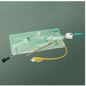
and others.[9] Refer figure 1.1 folex catheter asembly pack.
Figure 1.1: Folex Catheter Asembly Pack
In this sub-chapter, the overview of the product (catheter assembly) is
briefed. Foley catheters are soft and thin latex tubes that are passed through the
urethra during urinary catheterization and into the bladder to drain urine. They are
retained by means of a balloon at the tip which is inflated with sterile water. The
balloons typically come in two different sizes: 5 cc and 30 cc. A Foley catheter is
typically used when normal urination is disrupted by an infection, a swollen prostate
gland, bladder stones, or, sometimes, an injury. In very sick people, a catheter may
3
They were designed by Frederic Foley, a surgeon working in Boston,
Massachusetts, in the 1930s, when he was a medical student. His original design was
adopted by C. R. Bard of Murray Hill, New Jersey, who manufactured the first
prototypes and named them in honour of the surgeon.[25]
A typical Foley catheter has drainage lumen, and an inflation lumen for
inflating and deflating the balloon. The balloon is normally deflated until properly
positioned in a patient's bladder. Once the catheter is properly positioned, the
inflation lumen delivers fluid to inflate the balloon. The inflated balloon holds the
catheter in place. A Foley catheter having redundant temperature sensors includes a
catheter body with a proximal end and a distal end, an inflatable balloon disposed
near the distal end, an inflation lumen extending from the proximal end to the
balloon for inflating and deflating the balloon, a drainage lumen extending from the
proximal end to the distal end, at least one temperature sensor lumen extending from
the proximal end to the distal end, and at least two temperature sensors, each having
a wire and a sensor element, the sensor elements being disposed in the distal end of
the catheter body and the wires extending through the catheter body drainage lumen.
The temperature sensors electronically couple with a control unit, which
obtains a primary temperature reading from one of the temperature sensors and
obtains a secondary temperature reading from the other temperature sensors. The
control unit compares the primary and secondary temperature reading to determine a
difference.
The control unit establishes a threshold. The threshold is the maximum
acceptable difference between the primary and secondary temperature readings. This
threshold, according to one aspect of the invention, is set manually by an operator.
The control unit also includes an alarm so that when the difference between the
primary and secondary temperature readings exceeds the threshold, the control unit
activates the alarm. The alarm is audible according to one aspect of the invention and
another aspect of the invention, the alarm includes a video display and activation of
the alarm provides a video signal to the video display. In yet another embodiment,
the alarm simply shuts the control unit off.
A method of using a Foley catheter with redundant temperature sensors in
accordance with the invention includes the steps of introducing a Foley catheter into
the bladder of a patient and using the Foley catheter to drain urine from the bladder.
The method also includes electronically coupling the temperature sensors to a control
unit and activating the control unit to obtain the primary temperature reading and the
secondary temperature reading from the redundant temperature sensors. Obtaining
two, or more, temperature readings facilitates redundancy. One aspect of the
invention includes the step of comparing the primary temperature reading and the
secondary temperature reading to determine whether both sensors are operational.[9]
Another aspect of the invention includes three temperature sensors and an
appropriate methodology for detecting sensor failure. Three sensors enables
continued operation of the control unit to achieve meaningful temperature readings
notwithstanding the failure of one of the temperature sensors. It can be appreciated
that there are a variety of control and feedback methods that can accomplish
continuous operation of the catheter, sensors and control unit during a failure of one
of the sensors. According to an aspect of the invention having two sensors,
determining whether both sensors are operational is accomplished by comparing the
primary temperature reading and the secondary temperature reading to determine a
difference between the primary and secondary temperature readings. The control unit
deactivates when the difference exceeds the threshold. Preferably, the sensors
operate with an accuracy of ± 0.1 degree Fahrenheit. Accordingly a temperature
difference of a whole degree, for example, or more would typically indicate failure of
one of the sensors.
According to an embodiment of the invention the controller establishes a
5
preferably, however, the temperature threshold is about 1 degree Fahrenheit so that
the redundant sensors would operate safely in conjunction with a heat exchange
catheter system for regulating patient body temperature.
A major problem with Foley catheters is that they have a tendency to
contribute to urinary tract infections (UTI). This occurs because bacteria can travel
up the catheters to the bladder where the urine can become infected. To combat this,
the industry is moving to antibiotic coated catheters. This has been helpful, but it has
not completely solved this major problem. An additional problem is that Foley
catheters tend to become coated with time with a biofilm that can keep them from
properly draining the bladder. This increases the degree of static urine left in the
bladder, which further contributes to the problem of urinary tract infections. When a
Foley catheter becomes clogged, it must be flushed or replaced. Thus keeping Foley
Catheters from clogging may help reduce UTIs as well.
Foley catheters are used during the following situations:[25]
i. On patients who are anesthesized or sedated for surgery or other medical care
ii. On comatose patients
iii. On some incontinent patients
iv. On patients whose prostate is enlarged to the point that urine flow from the bladder is cut off. The catheter is kept in until the problem is resolved.
v. On patients with acute urinary retention.
vi. On patients who are unable due to paralysis or physical injury to use either standard toilet facilities or urinals.
Figure 1.2: Foley Catheter Designated with Reference Numeral 10 [9]
Figure 1.2 shows a Foley catheter generally designated with the reference
numeral 10. The catheter 10 includes a catheter body 12 with a proximal end 14 and
a distal end 16. The catheter 10 also includes a balloon 18, an inflation lumen 20, a
drainage lumen 22, and an adapter 24. The balloon 18 is deflated for insertion into a
patient. The balloon 18 is disposed near the distal end 16. The inflation lumen 20
extends within the catheter body 12 from the proximal end 14 to the balloon 18, in
fluid communication with the balloon 18, for inflating and deflating the balloon 18.
The catheter drainage lumen 22 extends from the proximal end 14 to the
distal end 16. The distal end 16 includes an opening 26 in fluid communication with
the drainage lumen 22 to facilitate drainage of urine from the bladder of a patient.
The adapter 24 has a drainage lumen 30, a temperature sensor lumen 32 and a
connector 25. The connector 25 attaches to the proximal end 14 of the catheter body
12. The connector 25 establishes fluid communication between the adapter drainage
lumen 30 and the catheter drainage lumen 22. Preferably the connector 25 is tapered
and includes ribs 27 for insertion and press-fit into the proximal end 14 of the
catheter body 12. The adapter temperature sensor lumen 32 includes a fitting 34 and
7
1.3 Overview on the Material of the Product (Catheter)
In this sub-chapter, the overview of the material of the product (catheter) is
briefed. Materials used for the construction of catheters including silicone rubber
latex and thermoplastic elastomers. Silicone is one of the most common choices
because it is inert and unreactive to body fluids and a range of medical fluids with
which it might come into contact. On the other hand, the polymer is weak
mechanically, and a number of serious fractures have occurred in catheters. It is
widely used, for example, in breast implants where failures by rupturing of the
silicone shell are well attested. They are commonly made in silicone rubber or
natural rubber.
Latex refers generically to a stable dispersion (emulsion) of polymer micro
particles in an aqueous medium. Latexes may be natural or synthetic. Latex as found
in nature is a milky sap-like fluid within many plants that coagulates on exposure to
air. It is a complex emulsion in which proteins, alkaloids, starches, sugars, oils,
tannins, resins, and gums are found. In most plants, latex is white, but some have
yellow, orange, or scarlet latex.[1]
The word is also used to refer to natural latex rubber; particularly for
non-vulcanized rubber. Such is the case in products like latex gloves, latex condoms and
latex clothing. It can also be made synthetically by polymerizing a monomer that has
been emulsified with surfactants. The term latex is attributed to Charles Marie de la
Condamine, who derived it from Latin latex, fluid.
The cells or vessels in which latex is found make up the laticiferous system,
which forms in two very different ways. In many plants, the laticiferous system is
formed from rows of cells laid down in the meristem of the stem or root. The cell
walls between these cells are dissolved so that continuous tubes, called latex vessels,
trees (Para rubber tree and Castilla elastica), and in the Cichorieae, a section of the
Family Asteraceae distinguished by the presence of latex in its members. Dandelion,
lettuce, hawkweed, and salsify are members of the Cichorieae. It is also present in
another member of the Asteraceae, the guayule plant.
In the milkweed and spurge families, on the other hand, the laticiferous
system is formed quite differently. Early in the development of the seedling latex
cells differentiate, and as the plant grows these latex cells grow into a branching
system extending throughout the plant. In the mature plant, the entire laticiferous
system is descended from a single cell or group of cells present in the embryo.
The laticiferous system is present in all parts of the mature plant, including
roots, stems, leaves, and sometimes the fruits. It is particularly noticeable in the
cortical tissues. Several members of the fungal kingdom also produce latex upon
injury. Notable are the milk-caps such as Lactarius deliciosus.[1]
1.4 Case Study at CR Bard Sdn. Bhd.
Study is carried out at CR Bard Sdn. Bhd. Kulim, Kedah. C.R. Bard focus is
on specific Disease State Management needs, both diagnostic and interventional, in
three key areas which are Vascular, Urology and Oncology. Main head quater is in
Murray Hill, New Jersey, USA. This company produce Latex Folex Catheters and
Urological Procedural Kits for medical users.[25]
In BARD latex folex catheter manufacturing process, some of the process
producing the part is still can be improved. One of the current process conditions that
9
stick. The process is done manually by operator which is require amount of an
energy to strip out the part after came out from chamber.
The current process is quite tedious and fully rely on the manpower who are
doing the job. Replacing humans in this task may improve efficiency and
productivity of the production and at the same time the manpower doing the task can
be trained or upgrade to some useful and important task.
Rationale to create automated system in this task is to get constant quality
force or energy of movement that are difficult or impossible to archive for human
energy.
Thus, beginning from conceptual design, development, fabrications and
measurement of the semi automatic stripping jig and fixture system, a systematic
procedure of Design and Development Standard and Boothroyd Dewhurst Design for
Manufacturing and Assembly (DFMA) methodology are chosen as a guideline in
order to achieve the target.
Simulation of processes, principle of operation, arrangement of Input and
output devices (sensors, switches, valves etc) will be showed as well.
1.5 Problem Statements
How the manual stripping process of latex folex catheter can be improved by
Related Questions
What are the important needs to be considered?
What are suitable concept designs to develop the model?
How to quantify the performance of the design model with several variables?
1.6 Objectives
The main objectives of this project is to design and development of an
automatic handling system in latex folex catheter manufacturing process by using a
PLC based system and quantify the performance of the design model.
1.7 Scope of project
This project will be focus on automating industrial processes.
Area will be focus on:
i. Identify the characteristics of the existing process and the need to develop
an automatic stripping system.
ii. Design and Develop a material handling system that stripping out latex
folex catheter from its former (mold).
iii. Characteristics of the existing process & the need to develop an automatic
11
iv. Evauate the productivity and reliability of the existing process and how
can the new developed automatic stripping system will improve the
handling of this process.
v. Analyze the performance of the design model.
The mechanism or conceptual design model need to be generated at the
begining. Then the best design concept model will selected and tested as well as the
analysis will taking place after selection has been made.
The analysis will consist of identifying and quantifying the area(parameters)
that contribute to the improvement in production area. Then correlating those
parameters and establish the mathematical model to represent the variable
interaction.
The project will be utilized a PLC (Programmable Logic Controller) with
appropriate mechanism design to make an improvement in chosen production
process (Stripping out catheter body from it former).
1.8 Outline of the Thesis
The thesis presents the implementation of the design and development
prototype model of material handling system which is stripping mechanism for
catheter from the former based on the design and development standard principle.
Chapter 2 focuses on the literature review, which introduces the overview of
the critical process that most required need to be studied. This chapter is then
described by related researches on stripping mechanism efficiency and some
standard for design and development, which is found to be related and facilitate to
this project.
Chapter 3 provides the methodology that is used through out the work of this
project. It covers the technical explanation of design and development standard based
on Karl Ulrich Steven Eppinger starting with gather raw data until design for
manufacturing and assembly. The model also been verified with the simulation of
stress and strenght of it former by using CosmosXpress software .
Chapter 4 deals with the generating of Computer Aided Design (CAD)
drawing complete with bill of material. Testing the performance results then done
thru an experimental method analysis of varians (ANOVA). The obtained results are
determine the effectiveness of the design prototype model.
Chapter 5 presents the conclusions of the project as well as some constructive
suggestions for further development and the contribution of this project. The project
outcome is concluded in this chapter. As for future development, some suggestions
are highlighted with the basis of the limitation of the effectiveness of the prototype
![Figure 1.2: Foley Catheter Designated with Reference Numeral 10 [9]](https://thumb-us.123doks.com/thumbv2/123dok_us/1368176.1169565/22.595.146.510.68.309/figure-foley-catheter-designated-reference-numeral.webp)
