18th International Conference on Structural Mechanics in Reactor Technology (SMIRT 18) Beijing, China, August 7-12, 2005 SMIRT18-D05-5
DEVELOPMENT OF THE NORMATIVE DOCUMENTATION FOR
CONTROL EXPLOITATION PIPE LINES OF SECOND SIDE NPP WITH
VVER
V.I. Baranenko, S.G. Oleynik, O.A. Belyakov, R.S. Istomin Electrogorsk Research and Engineering Center
Bezymyannaya street 6, 142530, Electrogosk, Moscow Region, Russia
e-mail: [email protected]
A.V. Kumov
VNIIAM, Volkov street 6a, 125171, Moscow, Russia
Abstract
Flow accelerated corrosion is the most common mechanism of metal degradation. NPP equipment and pipelines manufactured from pearlitic steel are exposed to erosion-and-corrosion wear. Recently many problems related to life management of NPP equipment and pipelines exposed to erosion-and-corrosion wear have been solved. The present paper analyzes the development, certification in supervisory authorities, and adaptation of normative documentation on life management of secondary pipelines operation at NPPs.
Keywords: erosion, corrosion, chemical content, water chemical regime.
1. INTRODUCTION
Flow accelerated corrosion (flow accelerated corrosion – FAC) is relatively new mechanism of metal degradation. Before the severe accident by reason of erosion-and-corrosion ware happened on NPP “Surry-2” in USA on December 1986, it was considered that reliable operation of NPP equipment and pipeline elements is assured during the design operation life. Therefore incoming and operation inspection of NPP line wall thickness were not carried out. After the accident the study of FAC problem was of great interest.
Study of foreign experience and native investigations was the basis for the elaboration of normative documents on management of NPP secondary pipeline life in Russia [1-4].
It was discovered that prediction and elimination of dangerous erosion-and-corrosion ware is possible in the presence of normative documents that include as follows:
1. Software on calculation and prediction of erosion-and-corrosion ware.
2. Technical instructions for determination of chemical composition of the pipeline metal.
3. Rates of metal strength analysis involving erosion-and corrosion ware. 4. Programme of metal operation control involving erosion-and-corrosion ware.
5. Technical instructions for acquisition and processing of data determining erosion-and-corrosion ware.
The frame to be solved by each established document was specified. 1. Software (computer codes) provides the potential for:
- the calculation of rate and value of pipeline elements thinning to determine their safety operation life;
- the calculation of rate and value of pipeline elements thinning in the course of modification of the design or replacement of structural materials;
- the calculation of rate and value of pipeline elements thinning on modification of water chemistry;
- the selection of structural materials with previously predicted operation life during the design and in the course of pipelines repairing;
- rejection of expensive stainless steel or pearlitic steel with large wall thickness in the course of repairing;
- replacement of defective parts of the pipeline for cheaper pearlitic steel with the concentration of chromium and copper ~(0.25-0.30) %.
2. Technical instructions for determination of chemical composition ensure the potential for determination of mass content of chromium, copper and molybdenum in NPP pipeline metal:
- under operation; - in the repairing;
- in determining a fail source of pipelines.
3. Rates of metal strength calculations ensure the potential for calculation of permissible thickness values:
- in general thinning of pipeline walls; - in local thinning of pipeline walls.
4. The programmes of metal operation control ensure as follows:
- optimization of the operation control scope of ultrasonic measuring of pipeline wall thickness exposed to FAC;
- rating of the pipelines by degree of corrosion-and-erosion exposure; - integral use of regulatory documents on corrosion-and-erosion ageing.
5. Technical instructions for acquisition and processing data ensure collection of data according to:
- indications of water chemistry;
- structural characteristics of the pipelines;
- structural materials used for manufacturing pipelines; - operation conditions of pipeline elements.
6. Technical instructions for selection of structural material ensure:
- integral use of regulatory documents on corrosion-and-erosion ageing to justify the selection of structural materials on designing;
- integral use of regulatory documents on corrosion-and-erosion ageing to justify the selection of structural materials on repairing.
7. Recommendations considering the effect of corrosion products deposition on operation control reliability make it possible:
- to consider the effect of corrosion-and-erosion ageing features on producing of corrosion products deposition;
- to consider the effect of corrosion product deposits on reliability of operation control (ultrasonic measuring of pipeline wall thickness).
The software (SW) EKI-02 and EKI-03 have been developed and are certified in the supervision authorities for Russian NPPs. The prototype of the developed Russian software is the US computer code CHECWORKS. The software EKI-02 is designed for the calculation of FAC rate in the pipelines of one-phase medium (water), and the software EKI-03 – for the calculation of FAC rate in the pipelines with two-phase medium (live and heating steam pipelines).
When calculating by means of the software sufficiently large data content on operating conditions, design philosophy and pipeline layout, water chemistry values, chemical composition of structural materials used, operation control data for each of calculated element in different operation periods, etc., should be available. Such data are not always available in domestic NPPs. That fact involves some difficulties when calculating corrosion-and-erosion ageing of the pipeline elements using the software. The development and introduction of technical instructions for acquisition and processing data ensure data collection at the stage of designing and in operation.
Figure 1 demonstrates a part of the feed water pipeline damaged on December 9, 1986, in NPP Surry-2. During the accident the feed water pipeline of 18 inches (457.2 mm) in diameter was broken. The Company-owner “ Virginia Power” informed that the broken pipeline was never examined during its operation since its life was designed for 40 years. Its maximum thinning was 11.5 mm. The pipeline was ruptured on 13 years of operation and resulted in severe consequences for NPP.
Figure 2 shows a part of the feed water pipeline damaged behind a throttling orifice in NPP Loviisa. A guillotine break in the area of welding was taken place and corrosion on the direct section behind the welding. Metal of flange coupling does not contain chemical elements preventing from corrosion-and-erosion propagation. Corrosion-and-erosion ageing of metal is less when chromium, copper and molybdenum in metal is 0.04% at the most. Damaged direct section is manufactured from carbon steel containing chromium, copper and molybdenum of 0.00 – 0.06%. Another direct section made of steel 20 is welded to the damaged direct section. Steel 20 may contain concentration of chromium and copper 0.25%.
Figure 3 presents control throttle flap in Kursk NPP. Corrosion is taken place in the area of flap welding to the valve. The section under effect of coolant flow of high velocity has damaged metal.
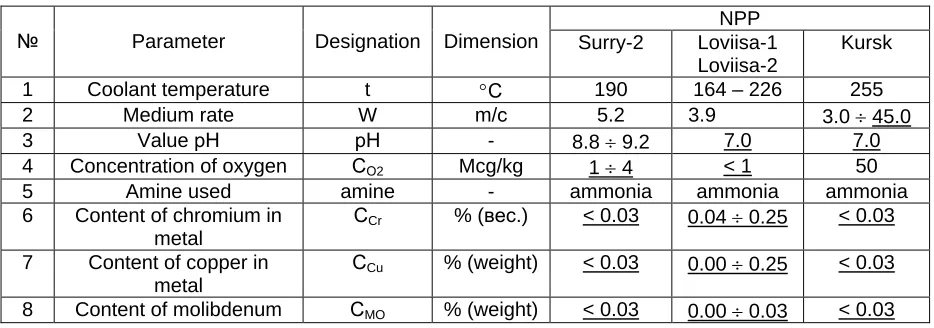
Table I includes the data required for the calculation of thinning resulted from corrosion-and-erosion ageing of PWR (Surry-2), WWER-440 (Loviisa 1,2) and RBMK (Kursk) NPP pipelines by means of EKI-02 software. Data given from the references below and available in NPP [5-12] were used for the calculation.
Table I. Data determining corrosion-and-erosion ageing of pipelines of different NPPs
NPP
№ Parameter Designation Dimension Surry-2 Loviisa-1 Loviisa-2
Kursk
1 Coolant temperature t °С 190 164 – 226 255
2 Medium rate W m/с 5.2 3.9 3.0 ÷ 45.0
3 Value рН рН - 8.8 ÷ 9.2 7.0 7.0
4 Concentration of oxygen СО2 Mcg/kg 1 ÷ 4 < 1 50
5 Amine used amine - ammonia ammonia ammonia
6 Content of chromium in metal
СCr % (вес.) < 0.03 0.04 ÷ 0.25 < 0.03
7 Content of copper in metal
СCu % (weight) < 0.03 0.00 ÷ 0.25 < 0.03
in metal
9 Keller factor КKEL - 0.45 0.08 ÷ 0.3 0.2 ÷ 0.9
10 Dimension-type of pipeline
Dхδ, mm mm 460х12 325х18 838х38
11 Operation time τOPER year(hour) 13 (76600) 13.2; 12.3 13 ÷ 22
Minimum thickness 1,2 mm
Figure 1. Corrosion-erosion ware of water pipeline (460х12,7) in NPP with PWR Surry-2, 09.12.1986 on 13 years of operation
1990
Figure 3. Corrosion-erosion ageing of the branch piece of throttling control valve (DRK 2MCP-21) in NPP with РБМК.
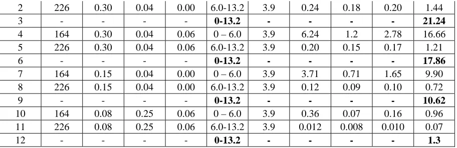
Table II includes the calculation results of corrosion-erosion rate and thinning values of damaged sections of feed water pipelines in NPP Loviisa. The calculations were made by means of the software EKI-02. First six lines of the table represent the calculation results for welding; maximum wall thinning was about 17 mm. First three lines represent copper concentration in metal – 0.00%, in lines - 4-6 – 0.06%. On calculations the time gap was divided conditionally into two parts. The first time gap was taken up to 6.0 years from operation start, the second time gap – from 6.01 years to 13.2 years. Conditional breakdown was made because it was still a question how long feed water didn’t pass through the heaters of high pressure (t = 164оС) and did pass (t = 226оС). Calculation difference was about (5 – 25)%.
Table lines 7-9 give the calculations for the damaged direct section. In this case calculation difference is about (3-15)%. The table includes the calculations only for the case when copper concentration in metal equals to 0.00%.
Table lines 10-12 represent calculations for intact direct section made of steel 20. It’s assumed that the concentration of chromium in metal is 0.25%. In this concentration of chromium the wall thinning would be about 1.0 mm for 13.2 years. In the concentration of copper 0.25% the wall thinning would be 0.72 mm, and concentration of copper 0.15% - 1.31 mm.
Table II. Calculation of FAC rate and thinning of damaged feed water pipeline sections in NPP Loviisa, CMo = 0,00 %, CО2 = 0.5 mcg/kg, рН = 7.0, D хδ = 325х18 mm, amine
№ T, оС KKEL CCr, % CCu, % τ, year Wt, m/sec Weki,
mm/year Weki,
mm/year Weki,
2 226 0.30 0.04 0.00 6.0-13.2 3.9 0.24 0.18 0.20 1.44 3 - - - - 0-13.2 - - - - 21.24 4 164 0.30 0.04 0.06 0 – 6.0 3.9 6.24 1.2 2.78 16.66 5 226 0.30 0.04 0.06 6.0-13.2 3.9 0.20 0.15 0.17 1.21 6 - - - - 0-13.2 - - - - 17.86 7 164 0.15 0.04 0.00 0 – 6.0 3.9 3.71 0.71 1.65 9.90 8 226 0.15 0.04 0.00 6.0-13.2 3.9 0.12 0.09 0.10 0.72 9 - - - - 0-13.2 - - - - 10.62 10 164 0.08 0.25 0.06 0 – 6.0 3.9 0.36 0.07 0.16 0.96 11 226 0.08 0.25 0.06 6.0-13.2 3.9 0.012 0.008 0.010 0.07
12 - - - - 0-13.2 - - - - 1.3
Table III gives the calculation results of corrosion-erosion rate and thinning of damaged feed water pipeline in NPP Surry-2. Maximum thinning of the pipeline wall in NPP Surry-2 was 11,5 mm. It is evident from the table that the calculation difference using EKI-2 is (38-43)% in this case. Error of thinning calculation by means of the software (computer codes) is determined by range of parameter change. It follows from Table II that pH values are within the range (8.8-9.2) and oxygen concentration within the range (1-4) mcg/kg. The error is taken place due to the fact that the values were not constant during operation. The less range of values the more accurate may be the calculation of corrosion-erosion rate and thinning of pipeline wall.
Table III. Calculation of FAC rate and thinning of feed water pipeline in NPP Surry-2, CCr = CCr = CMo = 0,03 %, D хδ = 460х12 mm
№ T, оС Kкел рН CО2,mcg/kg t, year
WT, м
/sec
Weki,
mm/year Weki,
mm/year Weki,
mm/year ∆S, mm 1 190 0.45 8,8 1 13 5.2 4.09 0.57 1.19 15.46 2 190 0.45 9.2 1.0 13 5.2 1.9 0.27 0.55 44013 3 190 0.45 8,8 4 13 5.2 4.33 0.60 1.26 16.39 4 190 0.45 9.2 4.0 13 5.2 2.02 0.28 0.59 23193
Table IV represents the calculation results of corrosion-erosion rate and thinning of damaged throttling-control valve in Kursk NPP
Table IV. Calculation thinning of wall tubes on Kursk NPP , Dt = 836х38 mm, CCr = CCu =
CMo = 0.03 %, W = 38 m/sec, pH = 7.0, CO2 = 50 ppb, KKel = 0.90, amin NH3 , τ = 13.0 years
Velocity, mm/year toC
In beginning Middle In end
Thinning of wall, after 28 years, mm
255.0 8.36 2.43 1.17 31.6
Corrosion-erosion ageing of the pipeline elements after long-term operation in NV NPP Unit 3 was calculated by means of SW EKI-02. Design values of maximum thinning of tensile sections of feed water pipeline bends are correlated with the data of operating control with error ± 20 %.
the range 0.03÷0.05 mm/year, and in SG-4, SG-5, SG-6 –over the range 0.09÷0.31 mm/year. One of the reasons for increased corrosion-erosion ageing of bends in SG-4, SG-5, SG-6 may be low content of chromium and copper in pipeline metal. In a series of measurements “thick” of pipeline walls was observed.
Table 5 gives processing of data on operating control of thickness of 38 bends of main pipelines of reactor compartment Ø 465×16 mm of NV NPP Unit 3 given in different time gaps. These data include maximum and medium thinning of tensile bend section as well as maximum and medium FAC rates. Analysis of results from operating control of UZ-thickness measuring in different time gaps make it possible to consider the reliability matter.
Table V – Corrosion-erosion ware of the tensile section of 38 bends of main pipelines of the reactor compartment in NV NPP Unit 3
Number of SG
№ Value Years
SG- 1 SG- 2 SG- 3 SG- 4 SG- 5 SG- 6
1 2 3 4 5 6 7 8 9
1 85-88 -3.5 -2.5 -0.5 -1.0 -2.0 -2.5
2 89-91 -2.9 - -3.0 - -3.7 -3.5
3 92-93 -2.5 -2.1 -1.1 -1.8 - -4.6
4
i max ∆S
mm
94-97 -3.5 -3.0 -1.6 -1.3 -2.2 -3.9
5 85-88 -0.25 -0.17 -0.036 -0.062 -0.22 -0.17
6 89-91 -0.16 - -0.17 - -0.185 -0.175
7 92-93 -0.12 -0.095 -0.052 -0.086 - -0.21
8
EKI max
W mm/year
94-97 -0.15 -0.12 -0.12 -0.054 -0.085 -0.16
9 85-88 -1.57 -1.75 -0.90 -0.75 -1.80 -1.75
10 89-91 -1.80 - -1.78 - -2.13 -1.67
11 92-93 -1.24 -1.25 +0.12 -0.87 - -2.23
12
i av
∆S
mm
94-97 -2.29 -1.02 -0.79 -0.33 -1.21 -1.51
13 85-88 -0.112 -0.117 -0.064 -0.044 -0.112 -0.117
14 89-91 -0.100 - -0.099 - -0.106 -0.083
15 92-93 -0.059 -0.057 -0.006 -0.041 - -0.101
16
EKI av
W
mm/year
94-97 -0.095 -0.041 -0.032 -0.014 -0.047 -0.060
Table V, lines 1-4, represents maximum thinning of tensile bend sections of steam generators SG 1 – 6 of NV NPP Unit 3 in different time gaps. The largest values are in thick print. It is evident from the table that first in all cases the largest thinning values exceed addition for corrosion 1.2 mm by 1,5 – 3,8 times. Secondly, maximum thinning values were not always registered during last monitoring. This is the evidence of the fact that the reliability of operation monitoring is not ensured properly.
Pipeline maintenance is accompanied by deposits formation on its internal surface. On measuring thickness by means of ultrasonic thickness gauges the thickness of unattacked metal together with the thickness of corrosion debris is registered. Special studies enable to establish that moist CP debris are registered in UZ-thickness measuring together with unattacked metal. Of total number of measurements 40038 thinning is registered in 12238 measurements (30,56% of total amount), “thick” – in 26711 (66,7% of total amount). This fact signals that thickness is registered more often during operation monitoring.
Other possible reasons of thinning/thick over and undervalues of pipeline walls must be shown. Generally acceptance tests of pipeline wall thickness are not performed in NPPs. Therefore initial data of pipeline thickness are not available. It should be emphasized that wall thickness limits while manufacturing is –5 % ÷ +20 % with respect to rating value. This factor may favor that thickness larger than nominal one in significant thick measurements is carried out in the course of operating monitoring.
Conclusions
1. Prediction and elimination of corrosion-erosion ageing of equipment and pipelines elements manufactured from pearlitic steel are possible with a package of normative documents.
2. Normative documentation package includes: - software for calculation and prediction of FAC;
- methodical instructions for determination of metal chemical composition; - strength calculation rate of metal with FAC;
- programmes of operating inspection of metal with FAC; - methodical guidelines for data acquisition and processing; - methodical guidelines for selection of structural materials;
- recommendations for accounting of corrosion products deposit for reliability of operation inspection.
3. Calculation performed for pipeline wall thinning by means of the software made it possible to determine that calculation error does not exceed 50%.
4. Analysis of calculation results provide a conclusion that the following factors determining pipeline wall thinning value may be referred to:
- absence or low concentration of chromium, copper and molybdenum in metal;
- composite geometry of damaged pipeline element contributing significant turbulization of coolant flow.
5. Low pH, low content of oxygen in the coolant, high velocity of the coolant, etc. is the worst case for initiation and propagation of corrosion-erosion wear.
References
1. V.I. Baranenko, НB.I. Nigmatulin, T.E. Schederkina, etc. Corrosion-erosion ageing of NPP equipment// Atomnaya technika za rubezhom,1995, №8, P.9-15.
2. V.I. Baranenko, I.V. Malakhov, A.V. Sudakov, etc. Nature of corrosion-erosion wear of pipelines in YuU NPP Unit 1// Teploenergetika, 1996, №12, P.55-60.
3. Chexal V.K. (Bind), Horowitz J.S. Chexal- Horowitz Flow-Accelerated Corrosion Model-Parametr and Influences. Current perspect. of Inter. Pressure vessals and Piping: Codes and Standard. Book No. 409768. 1995/ P.231-243.
4. NPP “Sarry-2” accident. Atomnaya technika za rubezhom, 1987, №10, P.43.
5. Chexal B., Mahini R., Munson D. CHECWORKSTM an integrated computer program for controlling flow accelerated corrosion. The forth Inter. Top. Meeting on Nuclear Thermal Hydraulias Operations and Safaty, Taibei, China, 5-9 April 1994. 6 p.
6. Bridgeman J., Ker R. S. Erosion/Corrosion data handling for reliable NDE. Nuclear Eng. and Design. 1991. V.131. P.285-297.
8. Chexal V.K. (Bind), Horowitz J.S. Chexal- Horowitz Flow-Accelerated Corrosion Model-Parametr and Influences. Current perspect. of Inter. Pressure vessals and Piping: Codes and Standard. Book No. 409768. 1995/ P.231-243.
9. Erosion-corrosion in power plant piping systems calculation code for predicating wall thining. Kastner W., Erwe V., Henzel V., Stellway B. Proceed. Specialists Meeting organized by the Inter. Atomic Energy Agency and held in Vienna 12-14 Sept. 1988. IAEA Vienna. P.49-59.
10. WATHEC and DASY Combat Erosion/corrosion. Bertich Energieerzeugung (KWU). Freyeslebenstrase 1. D-91051-Erlangen. 1994. 2 s.
11. Bouchacourt M. Predicting Flow Accelerated (Erosion/Corrosion) Damage in Power Plants with BRT-CICERO Code. Proceed. specialists meeting organized by Atomic Energy Agency and held in Kiev. Ukraina. 1994. P.314-334.