DEVELOPMENT OF A COMPRESSED NATURAL GAS (CNG) MIXER FOR A TWO STROKE INTERNAL COMBUSTION ENGINE
DEVARAJAN A/L RAMASAMY
DEVELOPMENT OF A COMPRESSED NATURAL GAS (CNG) MIXER FOR A TWO STROKE INTERNAL COMBUSTION ENGINE
DEVARAJAN A/L RAMASAMY
A thesis submitted in fulfilment of the requirements for the award of the degree of
Masters of Engineering (Mechanical)
Fakulti Kejuruteraan Mekanikal Universiti Teknologi Malaysia
v
ABSTRACT
vi
ABSTRAK
vii
CONTENTS
CHAPTER TITLE PAGE
TITLE i
DECLARATION ii
DEDICATION iii
ACKNOWLEDGEMENT iv
ABSTRACT v
ABSTRAK vi
CONTENTS vii
LIST OF TABLES xi
LIST OF FIGURES xii
LIST OF APPENDICES xiv
LIST OF SYMBOLS xv
1 INTRODUCTION 1
1.1 Problem Statement 2
1.2 Objectives 3
1.3 Scope 3
viii
2 LITERATURE REVIEW 5
2.1 Two Stroke Engine 5
2.2 CNG as Fuel for Two Stroke Engines 6
2.2.1 CNG as an Alternative Fuel 7
2.2.2 Combustion Characteristics of CNG 10 2.2.3 Emission Reduction from CNG Usage in
Two Stroke Engines 11 2.2.4 Other Issues Regarding CNG Usage 13
2.3 CNG Mixer 14
2.3.1 Current Trends in CNG Mixer Design 15 2.3.2 Sizing of the Mixer Throat 18
2.3.3 Pressure Drop in the Mixer 19
2.3.4 CNG Mixer and Engine Conversion Kits 23 2.4 Summary of Literature Review 24
3 DESIGN OF A VENTURI BURNER MIXER 25
3.1 Conceptual Design 26
3.2 Procedure of Mixer Design 28
3.2.1 Initial Throat Size 29
3.2.2 CFD Simulations of the Mixer 30 3.2.3 Inlet and Outlet Angles of the Mixer 34 3.2.4 Number of Holes at Throat Circumference 36 3.2.5 Size of Hole at Throat Circumference 37
3.2.6 Throat Size Optimisation 37
3.3 Prototyping the Mixer 38
3.4 Validating the Mixer Design 39
3.4.1 Testing Apparatus 39
3.4.2 Testing Procedure 42
3.4.2.1 Smoke Mixing in Mixer 43
ix
3.4.2.3 Pressure Drop Test 46
4 RESULT AND DISCUSSION 47
4.1 Designing of the Mixer 47
4.1.1 Initial Throat Size 47
4.1.2 CFD Simulation of the Mixer 48
4.1.3 Inlet and Outlet Angles of the Mixer 48 4.1.4 Number of Holes at Throat Circumference 52 4.1.5 Size of Hole at Throat Circumference 56
4.1.6 Throat Size Optimisation 58
4.2 Prototyping the Mixer 63
4.3 Validating the Mixer Design 65
4.3.1 Smoke Mixing in Perspex Prototype 65
4.3.2 AF ratio Testing of Mixer 67
4.3.3 Pressure Drop Testing of Mixer 69
5 CONCLUSION AND RECOMMENDATION 72
5.1 Conclusion 72
5.3 Recommendation 73
REFERENCES 74
APPENDICES 77
Appendix A 77
x
Appendix C 109
Appendix D 117
Appendix E 125
xi
LIST OF TABLES
TABLE NO. TITLE PAGE
2.1 Energy content of alternative fuels relative to petrol
and diesel 8
2.2 Proven natural gas reserves 8 2.3 Average natural gas composition in Malaysia 9
2.4 Methane gas properties 10
2.5 Typical 2-stroke emissions 12 2.6 Current regulation that is available for two-stroke
engines 12
2.7 Fuel price 13
3.1 Specification of the analysed engine 29
3.2 Properties of air 33
xii
LIST OF FIGURES
FIGURE NO. TITLE PAGES
1.1 Methodology 4
2.1 Operation of a two stroke engine 6
2.2 Type of CNG mixers currently being used in the market 15 2.3 Power test results for different mixer designs 16 2.4 Venturi upstream of the carburettor 18 2.5 Mixer after throttle in intake system of injection engine. 18 2.6 Schematic plot of velocity and pressure across a venturi 20 2.7 Pressure profile during intake stroke of an engine 21 2.8 Pressure drop in air cleaner and intake manifold 22 3.1 Methodology for designing the CNG mixer 25
3.2 The concept models 27
3.3 Proposed shape of the mixer 28
3.4 Location of throat diameter 30
3.5 Simulation steps for each simulation 32 3.6 Overall simulation stages done on the mixer 34 3.7 Simulation model for inlet and outlet angles 35 3.8 Schematic diagram of flow test rig to measure air flow 40 3.9 Schematic of smoke generator connected to test rig 41 3.10 Schematic diagram of pressure measurement 42 4.1 Pressure plot along the centre line of the mixer at different
inlet and outlet angles 49
4.2 Lowest pressure at the throat diffuser wall 50 4.3 Pressure ratios of each model inlet and outlet angle changes 51
4.4 Eight holes mixer model 53
xiii
4.6 Twelve holes mixer model 55
4.7 Effect of AF ratio on hole sizes at throat circumference
at all speed range 57
4.8 Effect of throat diameter size on air fuel ratio 60 4.9 Simulation pressure drop due to different throat size
at all engine speed 62
4.10 Perspex model for flow testing 63 4.11 Assembled view of Aluminium mixer 64 4.12 Components of Aluminium mixer 64 4.13 Simulation of smoke at 1000 rpm, 2000 rpm and 3000 rpm
air speed 66
xiv
LIST OF APPENDICES
APPENDIX TITLE PAGES
A Thesis Gantt Chart 77
B CFD Analysis 79
C Apparatus and Experiments 109
D Technical Drawings 117
E Material Selection 125
xv
LIST OF SYMBOLS
AF Air fuel ratio
-1
A
Area in inlet m22
A
Area at throat m2P
C Viscosity constant
-Cv Specific Heat J/kgK
Dr Delivery ratio
-HL Losses in pipe Pa
k Turbulent kinetic energy J/kg
1
m
Inlet mass flow rate kg/sN Engine speed rpm
a
Q Volumetric air flow rate m3/s
1
Q
Measured flow rate m3/s2
Q
Actual flow rate m3/satm
p Atmospheric pressure Pa
QH Heat source per unit volum e J/m3
qi Diffusive heat flux J/s
Si Mass-d istributed external force per unit mass N/kg
U Fluid velocity m/s
1
v
Velocity at inlet m/s2
v
Velocity at throat m/sp
' Pressure drop Pa
air P
' Pressure drop in the air cleaner Pa
u P
' Intake pressure drop upstream Pa
thr P
xvi
valve P
' Pressure drop across intake valve Pa
1
U
Air density at inlet kg/m3P
f Turbulent viscosity factor.
-ij
G
Kronecker delta function -H
Turbulent dissipation J/sT
Angle ºik
W
Viscous shear stress tensor PaP
Dynamic viscosity kg/m sl
P
Dynamic viscosity kg/m st
CHAPTER 1
INTRODUCTION
Current trends in the automotive industry are ever changing especially regarding the usage of alternative fuels. The search for the best alternative fuel that produces the least amount of emission has sparked concerns to many researchers. Maxwell (1995) stated that many studies on alternative fuel have been carried out and researchers are looking at natural gas, liquefied petroleum gas (LPG), methanol, ethanol, and hydrogen. All of these fuels have their advantages and disadvantages which are cost, availability, environmental impact, usage in vehicle, safety and the acceptance by consumers.
2
In automotive applications, natural gas can be used in three forms based on how the natural gas is stored. One of the most popular forms of natural gas is the compressed natural gas (CNG), which is natural gas in pressurised form. The other least popular methods of obtaining natural are liquefied natural gas and the absorption natural gas.
CNG is a good alternative to petrol and diesel. Consumers would easily accept this form of alternative as it has low operational cost due to subsidised price and its usage could provide cleaner engine emissions. The main reason behind CNG fuel being cleaner is that natural gas is principally comprise of 90% methane, which is the simplest form of hydrocarbon. Even so, the CNG fuel available today still lack in some qualities compared to petroleum fuel. For example, CNG fuelled engines normally possess lower engine performance compared to petrol.
The main reason is that CNG fuelling systems creates a lot of losses in terms of volumetric efficiency. This happens as CNG must be supplied to the engine through a mixing device before the mixture of CNG and air is drawn into the engine. This causes less fuel in the combustion chamber and reduces volumetric efficiency. Currently petrol fuelled engine are converted into a CNG fuelled engine by means of a fuel mixing device.
1.1 Problem Statement
3
The existing four stroke engine CNG mixers are usually not properly refined and optimised to enable good air fuel mixing. In addition, the efficiency of the current mixer design is also an issue as it is designed for simplicity which only offers practicality but lack in efficient air flow performance throughout the engine speed. Therefore, a straight forward conversion is not possible.
1.2 Objectives
The objectives of the study are as follows:
1) To design a venturi burner type CNG mixer for a two stroke engine according to the engine’s air requirement using CFD.
2) To fabricate the optimised prototype of the CNG mixer and test it on a flow bench machine.
1.3 Scope
The scopes of the research are as follows: 1) Preliminary design of the CNG mixer.
2) Optimising the CNG mixer design using CFD as a design tool . 3) Fabrication of the prototype CNG mixer.
4) Testing and validation of the CNG mixer design.
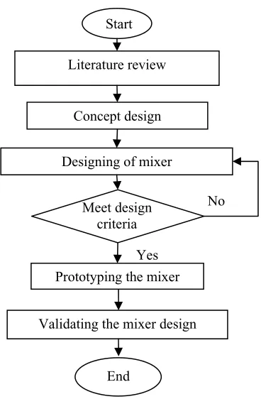
1.4 Methodology
4
Start
Literature review
Concept design
Designing of mixer
Figure 1.1 Methodology Prototyping the mixer
Meet design criteria
No
Yes
Validating the mixer design
REFERENCES
Andreas N. Alexandrou (2001). Principles of Fluid Mechanics. Prentice Hall. New Jersey.
Baert R. S. G., Beckman D. E., Veen A. (1999). Efficient EGR technology for future HD diesel engine emission targets. TNO Road Vehicles Research Institute. SAE 1999-01-0837.
Bryan Willson. (2002). Direct Injection as a Retrofit Strategy for Reducing Emissions from 2-Stroke Cycle Engines in Asia. Hong Kong.
Ferguson, C.R (2001). Internal Combustion Engines- Applied Thermo-sciences. John Wiley & Sons. Canada.
Gan L.M., (2003). Design and Development of Two Stroke Engine Using Blower Mechanism. UTM, Thesis.
Gas Malaysia Sdn. Bhd. (2003). Natural Gas in Malaysia. Gas Malaysia
Heywood J.B (1988). Internal Combustion Engines Fundamentals, Mc Graw Hill International Edition. Automotive Technologies Series
Jitendra (Jitu) Shah, N.Harshadeep (2001), Urban Pollution from Two Stroke Engine Vehicles in Asia, Regional Workshop on Reduction of Emissions from 2-3 Wheelers, September 5-7, 2001– Hanoi, Vietnam.
Landirenzo, (2003). TN-SIC CNG Regulators. Installation Manual. Landirenzo S.p.A. Italy
Lenz, H.P, (1992). Mixture Formation in Spark-Ignition Engines. SAE Inc. New York.
Luiz Henrique Borges, Carlos Hollnagel and Wilson Muraro. (1996). Development of Mercedes-Benz Natural Gas Engine M 366 LAG with a Lean Burn System. SAE Brasil 1996. 962378 E
75
Mardani Ali Sera, Rosli Abu Bakar, Sin Kwan Leong. (2003). CNG Engine Performance Improvement Strategy through Advanced Intake System.
Universiti Teknologi Malaysia. JSAE 20030229. SAE 2001-01-1937. Japan. Mikio Furuyama, Bo Yan Xu. (1998). Mixing Flow Phenomena of Natural Gas and
Air in the Mixer of a CNG Vehicle. SAE 981391. Chiba University. Japan. Mohamed Maurie Bundu. (1998). Investigation of the Performance of A Spark
Ignition Engine with Gaseous Fuels. Dalhouse University. Canada
Poulton M.L. (1994). Alternative Fuels for Road Vehicles. Computational Mechanics Publications. Southamton. UK and Boston. USA. Pg 99-121.
Rosli Abu Bakar, Azhar Abdul Aziz and Mardani Ali Sera. (2002a). Effect of Air Fuel Mixer Design on Engine Performance and Exhaust Emission Of A
CNG Fuelled Vehicles, 2nd World Engineering Congress Sarawak, Malaysia,22-25 July 2002
Rosli Abu Bakar, Mardani Ali Sera, Sin Kwan Leong. (2002b).Design and Development of New Compressed Natural Gas (CNG) Engine. IRPA Vot 72351. UTM.
Rosli Abu Bakar, Devarajan Ramasamy, Gan Leong Ming. (2004). Design of
Compressed Natural Gas (CNG) Mixer Using Computational Fluid
Dynamics. 2nd BSME-ASME International Conference on Thermal
Engineering. 2-4 January 2004. Dhaka
Rosli Abu Bakar, Devarajan Ramasamy, Chiew Chen Wee, (2003). Effects of Port Sizes in Scavenging Process on New Two-Stroke Engine Using Numerical
Analysis.3rdInternational Conference on Numerical Analysis in Engineering, Batam View Beach Resort, 13-15 March.
Sierra Instruments, (1994). Top-Trak Mass Flow Meters. Instruction manual. California. USA.
Taib Iskandar Mohamad, Mark Jermy, Matthew Harrison, (2003).Direct Injection of Compressed Natural Gas in Spark Ignition Engines. ICAST 2003.
Willard W. Pulkrabek, (1997). Engineering Fundamentals of the Internal Combustion Engine. Prentice Hall.
Yeap Beng Hi, Azeman Mustafa, Zulkefli Yaacob. (2002).Computational Investigation of Air-Fuel Mixing System for Natural Gas Powered
76
ISBN 983-52-0244-3