Speed Estimation of an Induction motor using
Model Reference Adaptive Control
Gopi N
PG Scholar, Dept. of E&IE, Dayananda Sagar College of Engineering, Bangalore, India
ABSTRACT:It is becoming essential to control the speed of an electrical drives, especially induction motors as they are considered to be the workhorses in many industries. This paper deals with the sensorless speed control of an induction motor by the use of vector control method. The importance of sensorless method is to reduce the losses that are created by the speed sensors due to the friction in the shaft. The vector control method is accurate speed control method than the V/F control technique (scalar method). The speed estimator used in this project is model reference adaptive control (MRAC). The MRAC estimates the speed from the voltage and current values. The estimated speed is compared with the required speed and the difference is fed to the controller. The controller controls the driving circuit of the induction motor. Hence the desired speed can be obtained. MATLAB based simulation is carried out for the closed loop implementation of the MRAC speed estimation and control of induction motor.
KEYWORDS:Induction motor drive; sensorless speed estimation; model reference adaptive control; field oriented control
I. INTRODUCTION
Induction motors are relatively compact and inexpensive machines. Therefore, much attention is given to their control for various applications with different control requirements. Among all types of ac machines, the cage type Induction motors are most widely used in industries. These machines are economical, rugged and reliable. These machines are available in ranges of fractional horse power(FHP) to multi megawatt capacity. Cage type induction motors does not require periodic maintenance like DC motors. However, because of its highly non- linear and coupled dynamic structure, an induction machine requires more complex control schemes than DC motors. Traditional open loop control of the induction machine with variable frequency may prove a satisfactory solution under limited conditions.
However, when high performance dynamic operation is required, these methods are unsatisfactory. Therefore, more sophisticated control methods are needed to make the performance of the induction motor better than that of a DC motors. Recent developments in the drive control technique, fast semiconductor switches, powerful and cheap microcontrollers made induction motors alternatives of DC motors in industries. The most popular induction motor drive control method has been the field oriented control(FOC) in past few decades. Furthermore, the recent trend in FOC is towards the use of sensorless techniques that avoid the use of speed sensor and flux sensor. The sensors in the hardware of the drive are replaced with state observers to minimize the cost and increase the reliability.
An induction machine, a power converter and a controller are the three major components of an induction motor drive system. Some of the disciplines related to these components are electric machine design, electric machine modelling, sensing and measurement techniques, signal processing, power electronic design and electric machine control. A conventional low cost volts per hertz or a high-performance speed oriented control can be used to control the machine.
Following are the advantages of sensorless induction motor drives,
• Reduced hardware complexity.
• Increase in reliability.
II. RELATED WORK
The controllers required for induction motor drive can be divided into two major types; a conventional low cost v/f controller and torque controller [1]-[4]. In v/f control, the magnitude of voltage and frequency are kept in proportion. The performance of the v/f controller is not satisfactory, because of the rate of change of voltage and frequency has to be low. A sudden acceleration or deceleration of the voltage and frequency can cause a transient change in the current, which can result in drastic problems. Hence DC motors are prominent choice for variable speed applications. Hassel and Blaschke introduced field oriented control, which is used to accomplish a decoupled control of flux and torque. This FOC concept is copied from dc machine direct torque control that has the following requirements
• An independent control of armature current to overcome the effects of armature winding resistance, leakage inductance and induced voltage.
• An independent control of constant value of flux.
If all these requirements are met at every instant of time, the torque will follow the current, allowing an immediate torque control and decoupled flux and torque regulation. De Doncker [5] introduced this concept in his universal FOC. In the air gap flux, the slip and flux relations are coupled equations and the d-axis current does not independently control the flux as it does in the rotor flux orientation. The measurement of the rotor time constant, its effects on the system performance and its adaptive tuning to the variations resulting during the operation of the machine have been studied extensively in the literature [6]-[8]. One advantage of saliency technique is that the saliency is not sensitive to actual motor parameters, but this method fails at low and zero speed level. When applied with high frequency signal injection [9], the method may cause torque ripples, and mechanical problems. Gabriel [10] avoided the special flux sensors and coils by estimating the rotor flux from the terminal quantities. This technique requires the knowledge of the stator resistance along with the stator, rotor leakage inductances and magnetizing inductance.
III.PROPOSED ALGORITHM
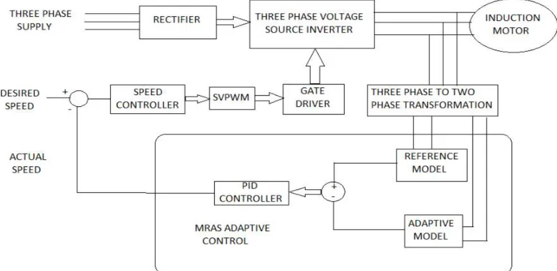
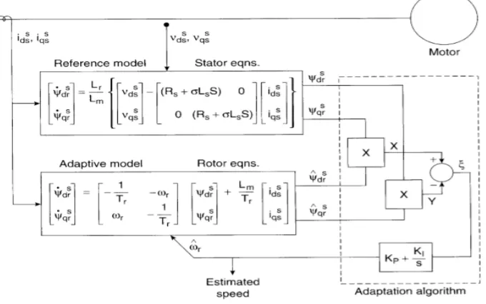
The block diagram of MRAC based speed estimation and sensorless speed control of IM is as shown below. The three-phase supply is given to the rectifier. The rectified DC output is given to the DC link inductor to smoothen the DC voltage. The DC voltage is fed to the three-phase voltage source inverter. The inverter output is then used to drive the IM. The three phase output values of voltage and current are transform into two phase values using Clark’s and Park’s transformation. The reference model takes the direct and quadrature values of voltage and current, this model is called the voltage model.
The adaptive model takes the direct and quadrature values of current and previously measured speed, this model is called the current model. The outputs of voltage and current model are subtracted and fed to a PI controller, which gives the estimated speed. The estimated speed is compare with the required speed and the error is fed to a controller(FOC). The controller output is given to the SVPWM (state vector pulse width modulation), which drives the three-phase voltage source inverter in order to obtain desired voltage across the IM and hence the speed.
Different components of the proposed model
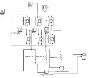
a. Three phase voltage source inverter
Inverters are the devices which convert DC to AC. In a three-phase voltage source inverter, the only way to control the output voltage is by changing the input DC supply.
Fig 2. Simulink model of three phase voltage source inverter with MOSFET’s as switching devices
The three-phase voltage source inverter used in this project is 180˚ scheme, where each device conducts for 180˚. The
switches are turned on at regular intervals of 60˚ in the sequence 1,2,3,4,5 and 6. The Simulink model with MOSFET’s
as switching devices is as shown in fig 2.
b. Internal control to the inverter
Output voltage of an inverter can also be adjusted by using a controller within the inverter. The most efficient method for adjusting output voltage is pulse width modulation(PWM). The PWM used in this project is state vector pulse width modulation(SVPWM), as it is superior of all in the PWM’s for variable frequency drive. SVPWM produces the switching control signal to be applied to the three-phase inverter. SVPWM is used for the creation of alternating current waveforms, which are most commonly used to drive the three phase motors.
Fig 3. Eight vectors in stationary frame.
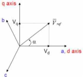
To realize the SVPWM, we have to determine Vd, Vq, α, time duration T1, T2, T0 and switching time of each sector.
Step1: Determining Vd, Vq and α.
Fig 4. Voltage space vector and its components in (d, q) coordinates.
From the above figure, we can write
= − cos 60− cos 60
= − 1
2 −
1 2 = 0 + cos 30− cos 30
= 0 + √3
2 −
√3 2
= +
Thus, from the value of ∝, the sector can be found.
Step 2: Determining T1, T2 and T0. The reference vector can be expresses by the combination of two adjacent vectors as shown in the fig 5.
Fig 5. Reference vector as a combination of adjacent vectors at sector.
= √ sin − (1)
= √ sin( )
(2)
= −( + ) (3)
The above three equations give the switching time at any sector.
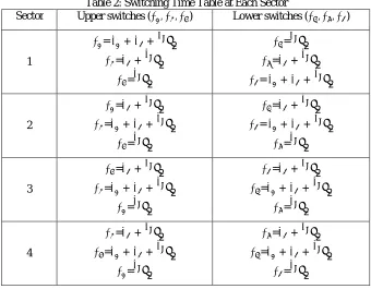
Step 3: Determining the switching time of each sector. The table have the information of switching time of each sector.
Table 2: Switching Time Table at Each Sector
Sector Upper switches ( , , ) Lower switches ( , , )
1
= + + 2
= + 2
= 2
= 2
= + 2
= + + 2
2
= + 2
= + + 2
= 2
= + 2
= + + 2
= 2
3
= + 2
= + + 2
= 2
= + 2
= + + 2
= 2
4
= + 2
= + + 2
= 2
= + 2
= + + 2
5
= + 2
= + + 2
= 2
= + 2
= + + 2
= 2
6
= + 2
= + + 2
= 2
= + 2
= + + 2
= 2
c. Field Oriented Control
Field oriented control (FOC) has the capability of controlling both the field-producing and the torque-producing currents in a decoupled way. the field oriented control can be classified into indirect or direct field oriented control, depending on how to obtain the rotor flux orientation. The direct FOC obtains the orientation of the mutual flux by installing a hall-effect sensor inside the induction motor. the indirect FOC is based on estimating the rotor flux orientation. By using the signals from the motor terminals such as three phase currents and rotor rotating speed, the rotor flux orientation can be estimated using motor state equations. Indirect FOC does not have the problems that direct FOC does, which makes it popular in most applications.
d. Model Reference Adaptive Control
The idea behind model reference adaptive control is to create a closed loop system with parameters that can be updated to change the response of the system. The MRAC consists of two important blocks named, reference and adaptive blocks. The output of these two blocks are compared until the error between the two models vanishes to zero. The block diagram for speed estimation using MRAC is as fig 6.
Fig 6. Block diagram of speed estimator by MRAC principle
Fig 7. Simulink block of MRAC with PI controller.
IV. SIMULATION RESULTS
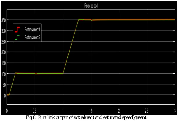
The above proposed model is simulated in the MATLAB/Simulink. The output of Simulink is as shown in fig 8. At 0 second the speed is set to 100 rpm but the motor takes a while to reach the speed and similarly at 1 second it is set to 350 rpm. From the Simulink result we can say that the actual speed(red) is almost equal to estimated speed(green). We can further make the estimated speed equal to actual speed by knowing the exact parameters of the motor.
Fig 8. Simulink output of actual(red) and estimated speed(green).
V. CONCLUSION AND FUTURE WORK
REFERENCES
1. B. K. Bose, “Power Electronics and AC Drives”, Prentice Hall, 1986
2. P.Vas "Sensorless Vector and Direct Torque Control" New York: Oxford University Press, (1998) 3. I. Boldea and S. A. Nasar, “Vector Control of AC Drives”, CRC Press, 1992.
4. D. W. Novotny and T. A. Lipo, “Vector Control and Dynamics of AC Drives”, Oxford University Press Inc., Oxford, New York, 1997. 5. R.D. Doncker and D.W. Novotny “The universal field oriented controller”, IEEE Tran. IA, vol. 30 no .1, pp. 92-100, January, 1994
6. R. Lorenz “Tuning of the field oriented induction motor controller for high performance applications”, IEEE Tran. IA, vol. 22, pp. 293-297, 1986 7. K.B. Nordin and D.W. Novotny “The influence of motor parameter deviations in feed forward field orientation drive systems” IEEE Tran. IA, vol.
21, pp.1009-1015, July 1985
8. R.Krishnan, F.C.Doran “Study of parameter sensitivity in high performance inverter-fed induction motor drive systems”, IEEE Tran. IA, vol. 23,pp.623- 635, 1987
9. P.L. Jansen and R.D.Lorenz “Transducer less position and velocity estimation in induction a salient ac machines”, IEEE Tran. IA, vol. 31, no.2, pp.240-247, Mar/April, 1995
10. Gabriel, Leonhard and C. Nerdy “Field oriented control of standard AC motor using microprocessor”, IEEE Tran. IA, vol.16, no.2, pp.186.192, 1980
BIOGRAPHY