Analysis and Design of Distribution of
Element Spacing of Micro strip Reflect
Array Antenna
Antara Ghosal1, Sisir Kumar Das2, Annapurna Das3
Assistant Professor, Dept. of ECE., Guru Nanak Institute of Technology, West Bengal, India1
Dean and Research Administration, Guru Nanak Institute of Technology, West Bengal, India2
Director, Guru Nanak Institute of Technology, West Bengal, India3
ABSTRACT: Reflect array antenna consisting of micro strip rectangular patches with average size of half wavelength on a thin FR4 dielectric substrate over a ground plane is described. The actual shape and spacing of the elements are designed depending on the feed horn pattern to produce phase pattern for pencil beam in a desired direction. Different spacing between the patch elements are considered for formation of plane wave front for pencil beam. MATLAB codes are developed for determining the induced surface currents on the patches due to incident radiation from the feed horn. Spherical to rectangular Co-ordinate transformations are automatically generated from the code and radiation pattern of the array is determined. Two basic inter-element spacings are considered, uniform spacing, and spacing with arith matic progression for optimum performance of 11x11 elements and 51x51 elements. . It is observed that AP spacing with decrement by λ/16 gives better result compared to uniform spacing.An experimental investigation has been carried
out on array of 51x51 elements and found agreement with theoretical results.
KEYWORDS: Reflectarray, Microstrip antenna.
I. INTRODUCTION
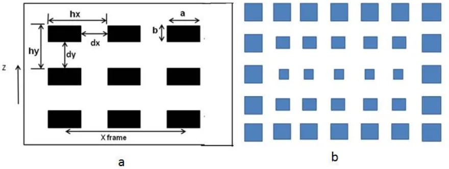
The schematic diagram of reflectarray antenna is shown in Fig. 1, which comprised of printed elements on a substrate of thickness h and relative permittivity and fed by a pyramidal horn antenna located at the virtual focal point F.
Fig. 1. Centre-fed reflect array(a. Uniform spacing b. Non uniform spacing
n
FO
FA
k
0(
)
A
2
(1)
where n is an integer representing the n th element at A where the first element is located at the origin O,
k
0is thefree space wavenumber, and
Ais the scattered phase generated by the patch located at point A. Right hand side of Eqn. (1) represents a phase difference of2
n
between nth patch and the patch 1 located at O, which is the center of reflectarray.For a scanned beam OB as shown in Fig.2, the phase relation
n
B
O
O
F
FA
k
0(
)
A
2
(2) must be satisfied.
Fig.2 A scanned beam reflect array
Lattice dimensions along the x-axis and y-axis, dx and dy, respectively are selected to be less than free-space half
wavelength
2
0
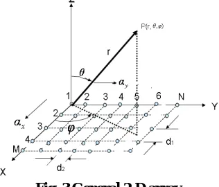
to prevent grating lobes. A general 2-D array is shown in Fig.3. The performances of reflect array
are derived from the general array theory while the excitation current on the elements is obtained from the induced current on the patches due to primary feed radiation from the virtual focus F. The pencil beam similar to paraboloid reflector is generated when the phase relationship satisfies the Eqns.1-2.
II. THEORETICALANALYSIS
In this paper, first a uniform array with 11x11 and 51x51 square patch elements are designed where each of the
elements are taken of equal size of dimension λ/2. The patches are equidistant from each other. Distance of the patches
from center to center is represented by hx and hy according to x axis and y axis, respectively. The feed horn antenna is placed in front of the center of the reflector plate.
Secondly, a non uniform array of equal square size elements with spacing according to Arithmetic Progression is taken to optimize the performance to yield broad side radiation with high gain. The geometrical representation of the array with feed is shown in Fig.4.
(a)
(c)
Fig.4 The geometrical representation of the array with feed Determination of coordinates of large number of array elements
The steps of analysis are the following where MATLAB is extensively used for all these computations: Determination of magnetic field radiation of horn at array elements in source co-ordinates.
Transformation of source co-ordinates into array co-ordinates and determination of induced current on the array elements.
Determination of antenna array factor from the induced current on the array elements.
Characterization of feed for Reflect Array Elements:
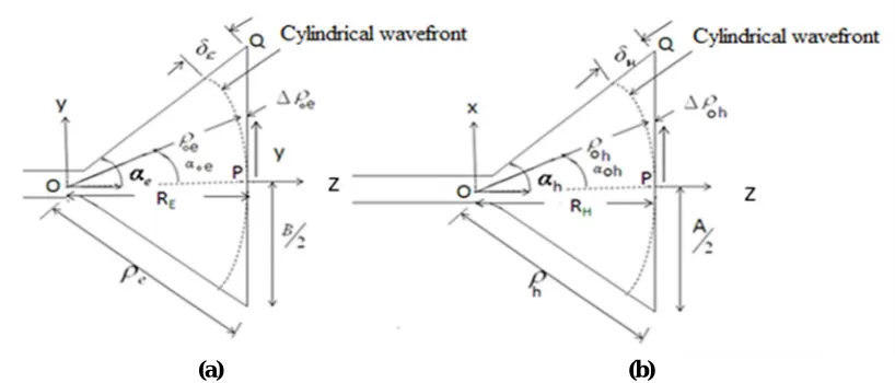
The reflect array elements are excited by the radiation pattern of a pyramidal horn antenna. To determine the aperture field components for dominant TE 10 mode and radiation pattern, a detail of dimensions of a typical pyramidal horn is required as shown in Fig.5.
The aperture field components are given by
h ey k x k j
y
x
e
A
E
y
x
E
02
0 2
2 2
0
cos
,
y
x
E
y
x
H
x y
,
,
---- (3)
(a) (b)
Fig. 5 Geometrical relationship in horn (a) for the E-plane, and (b) for the H-plane
Since the aperture field is linearly polarized along y direction, the radiated magnetic field components at point P (r’,
θ’, Φ’) with respect to horn coordinate system (x’, y’, z’) are given by[8]
y
d
x
d
e
e
x
A
E
r
e
j
H
jkx yy k x k j A A B B jkr e
h
sin sin cos sin 2 2 2 2 2 2 0 0 2 0 2cos
cos
1
sin
2
x
e
e
d
x
d
y
A
E
r
e
j
H
jkx yy k x k j A A B B r jk e h
sin sin cos sin 2 2 2 2 2 2 0 0 2 0 2cos
cos
1
cos
2
III.ANALYSISOFRADIATIONCHARACTERISTICSOFREFLECTARRAYANTENNA
In this analysis horn is considered in (x’, y’, z’) coordinate and the microstrip array is defined in (x, y, z) coordinate as shown in Fig.3. The positional coordinates of array element are determined for different elements spacing and sizes using MATLAB. The radiation field from feed horn is determined at these points using appropriate coordinate transformation from prime to unprimed system. After that the current at each of the element is determined. This leads to know the current distribution in array elements. From the knowledge of current distribution the radiation field or array factor of total reflect array is determined.
MxN Array (odd) case: each element= LxW Edge to edge spacings: dx along x and dy along y Successive center to centre spacings:
hx =dx+L and hy =dy+W
OA=xi =2hx =(i-1)hx ; i=(M-1)/2 AB=yj =2hy =(j-1)hy ; j=(N-1)/2
)
(
x
2
y
2---- (5)
Transform r’,
θ
'
,φ
'
of horn radiation pattern into xi and yj i.e., (i-1)hx and (j-1)hyThe radiated fields of the reflect array have been computed from the equivalent induced electric current densities
i r
s
n
H
H
J
ˆ
on the front surface of the array. Here
H
i
the field on the patches incidents from horn
radiation and
H
r
=reflected field on the patch surfaces, and
n
ˆ
is the unit vector normal to the reflector surface at the point of reflection.Applying boundary condition on the metallic reflector surface electric current density is determined from the magnetic field on the patches:
i r
is
n
H
H
n
H
J
ˆ
2
ˆ
H
H
H
i
ˆ
ˆ
In order to determine the induced currents on the patch elements following Co-ordinate transformations are made in Eqns.(1.3) and (1.4 )
x
r
sin
cos
x
y
r
sin
sin
y
z
r
cos
R
z
Here R is the far field distance between horn aperture and the surface of the reflect array. Array Factor of reflect array
After calculating the surface current for each patch, the array factor is computed by substituting the respective magnitude and phase of the surface current in the array factor equation for equally spaced array with non-uniform excitation amplitude. The general array factor is given by
jmN
m m
e
a
AF
1
0
Here, a0, a1, a2,…, am are the excitation amplitudes of the respective rectangular patches, and
is the phase difference between successive elements.Since beam steering in space involves both θ and Φ angles, inter-element phase shifts are required in two orthogonal directions (X and Y) in two-dimensional reflect array. Let the inter element spacing, inter element phase difference of excitation and the number of isotropic elements in x and y –directions are hx and hy, αx and αy, M and N,
respectively.
The array factor will be in two orthogonal directions and are given respectively, by
x jm M
m m
x
a
e
AF
10
and
y
jn N
m n
y
a
e
AF
1
0
---- (9)
---- (10)
---- (11)
---- (7)
Where,
x x
x
h
2
sin
cos
y y
y
h
2
sin
sin
Ψx and Ψy are the phase difference of the radiation field point from two consecutive sources in x and y directions
and αx, αy are the consecutive inter-element phase difference in x and y directions, respectively.
Total Array Factor,
AF
AF
x
AF
y (14)Normalized Array Factor,
AF
maxAF
NAF
(15) The radiation pattern of the reflect array is computed from the array factor equation using MATLAB. The basic definition of other important parameters as stated in case of parabolic hold good:
IV.RESULTSOFINVESTIGATION
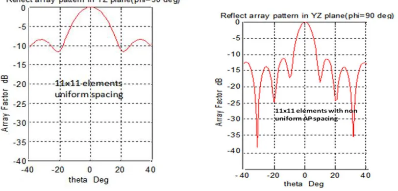
It has been observed that for both 11x11 and 51x51 array produce better results in terms of side lobe level for array spacing progressively decreases in accordance with arithmetic progression.
d
/
8
(m
-
1)
/(3
P)
; P=(M-1)/2, m= 1 for center element; m=1,2,3…. (M+1)/2, where M is the total number of elements along a given axis. Theoretical results for 11 x 11 elements with uniform and AP spacing are shown in Fig 6.
Fig. 6 Reflect array radiation patterns for 11 x 11 elements
In order to obtain experimental results a large size reflector array with 51 x 51 elements is designed and fabricated with element size
/
2
/
2
and inter element spacingd
/
8
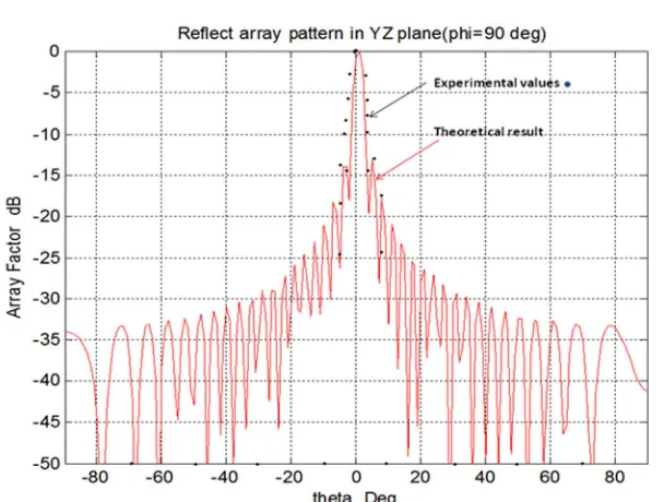
. A photograph of the experimental set using gun diode source and horn feed is shown in Fig.7.Both the theoretical and experimental results are shown in Fig 8. Due to sensitivity limitation of the measurement set up, experimental results are limited to first side lobe only and matches well with the theoretical main lobe.
---- (12)
Fig 7 Experimental setup
Fig 8. Reflect array radiation pattern for 51x51 elements
V. DISCUSSIONANDCONCLUSION
Due to directional pattern of the feed, there is non-uniform phase distribution of illumination of the array. It is, therefore, necessary that elements are spaced non uniformly to satisfy the phase condition of Eqn,(1-2). Therefore, some improvement of the radiation pattern of the reflect array is observed for inter element spacing according to Arithmatic Progression.
REFERENCES
1. Sridhar Bilvam, Malathi Kanagasabai, Sandeep Palanisamy, Phang Than Cong “Novel Ku Band Reflect array Antenna for Satellite Communication" in International Journal of Communications, Volume 1, 2016, ISSN: 2367-8887
2. J. Huan, “Analysis of a Microstrip Reflectarray Antenna for Microspacecraft Applications" in TDA Progress Report, February 15, 1995 3. D. M. Pozar and T. A. Metzler, “Analysis of a reflect array antenna using microstrip patches of variable size,” Electron. Lett., vol. 29,
Apr. 1993,pp. 657–658.
5. M.G.N.Alsath ,M.Kanagasabai and S.Arunkumar, "Dual-band dielectric resonator reflect array for c/xbands," IEEE Antennas and wireless Propag. lett., vol. 11, pp. 1253–1256,2012.
6. J.Huang and Jose A.C ,Reflect array Antenna. IEEE Press, New York: Wiley, 2008.
7. Jafar Shaker, Jonathan Ethier, and Mohammad Reza Chaharmir, "Reflectarray Antennas: Analysis, Design, Fabrication, and Measurement" Artech House, 01-Nov-2013 - Technology & Engineering
8. Antenna and Propagation By Annapurna Das, Sisir K Das
9. C.A.Balanis , Antenna Theory .. Analysis And Design (2nd Edition)
BIOGRAPHY
Antara Ghosal is presently assistant professor in the Dept. of ECE, GNIT, Kolkata. She obtained B.Tech degree in ECE and M.Tech degree in MCNT from West Bengal University of Technology in 2009 and 2011, respectively. Her research interests are Electromagnetics, microstrip antenna, mobile communication. She is a member of IEEE.
Sisir Kumar Das, Obtained B.Tech, M.Tech and Ph.D degree from Calcutta University, IIT kharagpur and Anna University, respectively in India. He was faculty in Delhi University during 1977-1980. Dr. Das led EMC evaluation and design of electronics products manufactured by the industry meeting International Standards and Electromagnetics Research projects in the country and abroad for 28 years under the ministry of communication and IT, Govt. of India, during 1980-2007. Presently he is Prof. and Dean – Research & Administration, GNIT, Kolkata. He is co-author of Engineering Text Book “Microwave Engineering”, published by Mc-Graw Hill, USA, Singapore and India.He is the author of the text book “Antenna and Propagation”, published by Mc-Graw Hill India. He has written three chapters in the book “Engineering EMC”, Published by IEEE press. He has nearly 120 research publications in journal and conference proceedings.Dr Das served as associate editor for IEEE EMC journal, USA (1994-2000) and now chief Editor of EMC journal of Society of EMC Engineers (India). He is senior member of IEEE, Life member of Society of EMC Engineers (India). He received society of EMC Engineers (India) highest award 2002 in recognition of his contribution to the EMI/EMC Solutions for Indian Industrial Products.