Strategy for a robot soccer team
- Let’s play robot soccer -
Master’s Thesis by:
R. R. Heddema
Graduation committee:
Dr. M. Poel Dr. A.L. Schoute
Ir. T. Verschoor Ir. I.H.C. Wassink Ir. H. van Welbergen
Faculty of EEMCS University of Twente
The Netherlands
Abstract
Vital for the success of the robot soccer system is a streamlined strategy. Robot soccer strategy is a form of decision making for robots. On the soccer pitch, robots, divided in two teams, interact with each other and a ball, each trying to win a soccer match. In a streamlined strategy, robots in the same team try to maximize the scoring opportunities for their team and minimize the scoring opportunities of the opponent by means of strategic plans.
Already for robot soccer, strategy research has been directed towards the use of weighted linear functions. However, for creating and adapting strategies, the use of a weighted linear function seems to be complex.
This thesis presents a different direction in strategy design. This uses finite state
machines (FSM) to create directed positioning for the robots. The transitions of the state machines consist of guarded plans, where the guards are based on existing
observations. Observations represent expert knowledge about situation on the robot soccer pitch and plans represent expert knowledge about the strategic means for the robots. In the FSM approach, strategies are represented explicitly by assigning roles to robots and modeling the desired behavior for each role with an FSM. Two of such
strategies are given, namely the “2-2 formation” and “1-3 formation with rotational tactic”.
Preface
To conclude the study Computer Science at the University of Twente I choose to participate in the robot soccer project. In this project, different aspects of the study are combined. I joined this project because it brings theoretical knowledge, learned in my study, into practice.
With the robot soccer team, we attended at international tournaments. These
tournaments were most enjoyable. During the attendance to the different tournaments, we showed real progress and this resulted in a 2nd place at the European Championship in 2007.
Finally, I would like to thank some people. First, I would like to thank my supervisors during this project; Dr. M. Poel, Dr. A. L. Schoute, Ir T. Verschoor, Ir. I.H.C. Wassink and Ir. H. van Welbergen. They helped to bring structure to the many incomprehensible expressions of my ideas. In addition, I want to thank my project members; Joost van der Linden, Maarten Buth and Paul de Groot. The teamwork with these project members made a lot of demonstrations and matches possible. I want to thank the rest of the students in room 2070 for the great lunches and discussions. Furthermore, I want to thank my parents Rein Heddema and Piety Heddema-Calsbeek. Without them, it is very doubtful that I ever attended university at all.
I want also to thank my brothers and sisters, because they stayed interested during my never-ending study. Last, but not least, I want to thank my lovely girlfriend Akke Kelder, for the support during the whole process of my final assignment.
Contents
1 INTRODUCTION ...5
1.1 THE GAME...5
1.2 THE CURRENT SYSTEM...5
1.3 PROBLEM DEFINITION...8
1.4 REQUIREMENTS FOR STRATEGY...9
1.5 OUTLINE...11
2 A FSM APPROACH TO STRATEGY DESIGN...12
2.1 INTRODUCTION TO FSM AND STRATEGY...13
2.2 AFSM FOR A SINGLE ROLE...16
2.3 AFSM BASED STRATEGY FOR A TEAM...17
2.4 EVALUATION...19
3 DESIGN OF DIFFERENT STRATEGIES FOR THE MI20 TEAM ...22
3.1 AVAILABLE OBSERVATIONS AND PLANS...22
3.2 DESIGN OF A 1-3 STRATEGY...23
3.3 DESIGN OF A 2-2 STRATEGY...30
3.4 EVALUATION...36
4 UNDERLYING SYSTEMS ...39
4.1 ROBOT IDENTIFICATION...39
4.2 MOTION...39
4.3 STATE ESTIMATION...43
4.4 COLLISION AVOIDANCE...44
5 CONCLUSIONS AND RECOMMENDATIONS...50
5.1 CONCLUSIONS...50
5.2 RECOMMENDATIONS...51
6 BIBILIOGRAPHY ...53
A APPENDIX...54
A.1 MOTIVATION FOR DISTRIBUTED PLAN GENERATION...54
A.2 COORDINATION BETWEEN PLAYERS...54
A.3 PLAN’S POSITION CALCULATION...56
A.4 COLLISION RECOVERY...57
1 Introduction
Robot soccer is a very attractive game that gives researchers all over the world the means to demonstrate the current state of new technology. It provides a test bed for new technology in image processing, robot hardware, motion control and artificial intelligence. This chapter first discusses a set-up for a robot soccer game. Second, it discusses the system with which the MI20 team plays robot soccer. In addition, existing problems are mentioned. Third, the problem definition is given and this chapter ends with the outline of this thesis.
1.1 The
game
The MI20 team [1] participates in a FIRA league [2]. MI20 plays its matches in the MiRoSot league [3]. In this league, robots have maximum dimensions of 7.5 x 7.5 x 7.5 cm, and use a two-wheeled differential drive. At the University of Twente Dr. M. Poel and Dr. A.L. Schoute lead the project.
Figure 1 Set-up of the MiRoSot game
Figure 1 shows the typical set up of a MiRoSot game. In a game, two teams play against each other. Each team has its own camera, transmitter, robots and computer. The camera observes the field and the transmitter sends radio signals to the robots.
1.2
The current system
The first version of the MI20 system was developed in 2002 [10]. Maarten Buth [8], Paul de Groot [9] and I, have developed the currently used system, also known as the second version.
This section will first show the architecture of the current system. Next, it discusses the previous developed Strategy modules in the MI20 project and its relevant experienced problems regarding Strategy.
1.2.1 Software
modules
the different software modules; Vision, State Estimator, Strategy, Motion and
RFcomm. Figure 2 shows the system architecture.
Tranceiver Vision
State Estimator
Strategy
Motion
RFcomm World Data
ActionSet SnapShots
Velocities MI20 System
Camera
Figure 2 System architecture MI20 v2.0
Vision
The Vision module is responsible for retrieving relevant information from the images
send by the camera. A data type called Snapshot combines the positional information of all robots and the ball. For the team robots, the Snapshot containsalso their orientation.
State estimator
The State Estimator its responsibility is, to approximate the real world situation as
good as possible. Filtering techniques and prediction correct the noisy delayed vision information. It also determines derivates like linear and angular speed from the
Snapshot. The estimated information is being stored in a data structure called World
Data.
Strategy
This module creates strategic Actions for the robots. The strategy depends upon the information given by the State Estimator. The strategy module has to retrieve meaningful information from so-called World Data and creates Actions for robots to execute. It is necessary that the Motion module can adequately execute Actions. These Actions are stored in a data structure ActionSet. Yet it is not the responsibility for the strategy module to create smart team play; Human operators and strategy module designers should realize smart team play.
Motion
The Motion module is important with regards of the ability to utilize the robot
effectively. It depends upon the functioning of the robot on the field and the task it has been assigned. Some important tasks are moving as fast as possible to a certain point, following as accurate as possible a moving target and intercepting a ball. The Motion
Rfcomm (Radio Frequency Communications)
The RFcomm module utilizes the different communication devices of the robots.
RFcomm sends Velocities, translated into adequate radiosignals, and sends it to
each robot by using the transceivers.
This thesis will describe work related to the strategy module. In the MI20 project, research has already been done for strategy module.
1.2.2
Previous work on Strategy
Seesink [1] developed the the Strategy module in the first version of the MI20 system. Using feature extraction, the module transformed the input space into more suitable strategic information. Adaptations to this strategy module were being made by Poelman [6] and van Amstel [7]. Petit [5] investigated a second approach for the
Strategy. Petit created a decision system based upon potential fields.
Next the so-called Single Neuron Approach developed by Seesink [1], which has also been implemented and used in tournaments, and the Potential Field Approach by Petit [5] will be discussed.
Single Neuron Approach
The Single Neuron Approach uses a weighted linear function, like a single neuron, to create output from a given input. The idea of the single Neuron Approach is first to transform the state vectors in World Data[1] of different objects on the robot soccer field into features [1]. Each feature has a semantic meaning (expert knowledge) about a certain aspect of the game. For example a feature could indicate to which extend a team player has a scoring opportunity. In Seesink’s [1] design these features are not based upon game statistics, but only upon the locations of the different robots and the ball. Second, the method combines the values of the features with reward and penalty weights and these weights can differ for the different roles. For each logical plan [1] the value of this combination is a measurement for the desirability for this plan. Third, the method chooses the most desired plan. A logical plan can be queued after or replace the current plan which has to be executed by the motion part of the system.
Potential Field Approach
The potential field approach proposal by C. Petit [5] distinguishes two parts in
Strategy. One part chooses an interception strategy that is case-based and selects
one robot as an on-ball player [5]. The other part assigns plans for the other robots in a supporting strategy. Potential fields are the basis for the design. The approach creates one potential field for all robots. The method retrieves all strategic positions from this potential field. First, a desirability value is computed for each position in the field, this leads to a potential field. The desirability value is based upon an additive combination of sub-functions. Such a sub function creates desirability values for a certain plan at each position on the field. The method creates a combined field from the desirability fields. Second, the method selects the top positions from the combined potential field. Third, the method allocates these positions among the robots.
The advantage of the Single Neuron approach is that it facilitates in easy adding expert knowledge to the system by means of features. This approach also has some
1.2.3 Problems
current
system
First with regard of strategy, general problems, which previous project members observed, are considered. These problems have to be considered with regard of the design for the new strategy module.
• Limited computational time [9]
Due to the real-time nature of the system, which has to process camera images with approximately 33 fps, strategy has limited time to make strategic decisions. For example, this means that for strategy it is not practical to search for all possible states in the robot soccer game to calculate the ‘perfect’ decision.
• Strategy has no recovery techniques
Stuck robot detection is one part of resolving deadlock situations in the robot soccer game [1]. For example not recovering robots with regard of failure with shooting attempts [12], [9], [13] exists.
Second, with regard of the implemented strategy of Seesink[1] some problems are considered. These problems are discussed because this one has been implemented and used by several people. According to Petit [5], Maatman and Poelman [6] and van Amstel [14] there is a great disadvantage for this design:
• Strategy design is complicated.
The way to adapt strategy is nontransparent [5], therefore it is difficult to change team play [6]. Coordinated team play, with the use of resource claiming [1], is realized at a laborious way [6]. Furthermore, the evaluation function that is realized with a combination of different matrixes is difficult to adjust to let the team play well [14].
Third, problems in the current version for the Strategy with regard of input and output for this module are mentioned.
• Unreliable World Data
The State Estimators robot-tracking algorithm often fails during game play. As
result, the State Estimator sends faulty World Data to the Strategy module. If tracking fails, the Strategy does not know where which robot is.
• Inadequate transformation of Actions to Velocities
Frequently changing the Actions results in slow control speeds being sent to the robots by the Motion module. This makes the execution of the Actions
inadequate. Especially a moving ball causes the change of the attributes for these Actions.
• No collision avoidance for practical use in the Motion Module
The Motion module does not provide in collision avoidance. This also makes
the execution of actions inadequate.
The new design for the Strategy Module shall consider these problems.
1.3 Problem
definition
Since 2002, MI20, the robot soccer team of the University Twente has participated in the MiroSot league. It was difficult to give demonstrations and to play games after a number of year’s development. This is caused by several problems. Among other things the strategic planned behavior of the robots was difficult matched with the developed
The most important task includes designing a new Strategy, which can be used for playing games and giving demonstrations. An important requirement of the Strategy is that strategic planning takes place for the robots. Strategic observations and strategic positions based upon expert knowledge will be used. Second, it must be easy to translate strategy to behavior and the other way around. This can be reached by changing the set-up of the Strategy and to simplify the decision process.
For this task, the next research questions are found:
RQ1: How can the Strategy module be designed in such way that it creates strategic
Actions for robots to execute?
RQ2: How can the strategy be designed that it is easily recognized in the observed
behavior?
Another task is to ensure that the requirements, which are necessary for the adequate execution of the Actions of a Strategy for MI20 the system, are met. The requirements for a good strategy are reliable information and adequate supervision of the robots. A good Strategy alone cannot ensure team play. For that there is looked first at the following components of the system of which the methods will be improved; Robot Identification, Collision Avoidance, Motion.
For this task, the next questions to be answered are found:
Q1: Which method can be used to provide strategy with consistent information?
Q1.1: How can robot identification be designed in such way that identification
can be performed at each moment during a robot soccer game, without the need for a tracking method?
Q2: How can adequate supervision of the robots be achieved?
Q2.1: Which techniques can be used to keep the robots pursuing the team
goals while keeping the robots free from deadlock situations?
Q2.2: Which techniques can be used to move the robots in such a way that
they are able to respond adequately to frequently changing actions?
1.4
Requirements for strategy
Different requirements are distinguished. One is with regard to the design of the Strategy Module in which a strategy for team play can be defined. A set of metrics is chosen to measure the improvement of the new system and the new approach for the strategy should perform equal or better for these metrics than the previous methods. Pressman [11] writes more about the use of metrics to measure model quality. The selected metrics are partly inspired by Pressman and partly specific for the robot soccer application. The other requirement encapsulates the behavioral team goals for a strategy for team play.
Metrics
This section considers the metrics for the Strategy module. With this metrics, the different approaches for the Strategy module are compared. These metrics are focused at the problems mentioned in 1.2.3. The Strategy module has to create strategic
Actions and it should facilitate the support of a strategy definition that is easily
recognized in the observed behavior of the robots.
M1: Support of time based behavior.
To enable stuck robot recovery and provide solutions for failure in shooting attempts. Time based behavior is characterized by behavior that is
M2: Computational complexity
To keep the CPU load of the system in mind, the computational complexity for the strategy module should be kept low.
M3: Understandability.
The more information programmers can comprehend about the strategy module, the smarter a strategy for robot soccer play can be designed. The module should be well understood and dependencies between internal, external and shared components should be well understood. Team play should not be realized in a time-consuming way.
M4: Reductive explainability.
Important aspect of this metric is that, what one can see in the team play is the same as what has been defined for team play. System states and important variables should be visible during execution. With good reductive explainability, incorrect output can be identified. It should not be difficult to see how the combination of different techniques leads to team play.
M5: Adaptability.
This metric is mainly driven by the effort one has to take to locate and fix an error in the system, or to change something to strategy which is needed as response to some specific weakness against opponents.
M6: Extensibility.
The degree in which the architectural data and procedural design of the strategy module can be extended. Furthermore, the degree in which one understands how they can extend the strategy module.
Team goals
In 1.2.1 it is already mentioned, that defining smart team play is the task of the designer of the Strategy module. Two important team goals focus the team play of the robots on winning the robot soccer game.
TG1: Scoring
TG2: Prevent the opponent from scoring
The listed team goals are guidelines for team play strategy development, in other words; guidelines for the strategy developers.
1.5 Outline
The purpose of this thesis is to describe ways to improve the Strategy module and strategic team play for the robots of the MI20 team. Chapter 2 describes the design of the
Strategy module. The Strategy module facilitates in the selection of different strategies
2
A FSM approach to strategy design
The Strategy Module is responsible for assigning an Action to each robot. These
Actions are stored in the ActionSet. Strategy is provided with World Data to make adequate decisions. This chapter will discusses the possibility of if Action generating with a state machine (FSM) driven approach.
The responsibility for the Strategy Module is to assign an Action to each robot. Then strategy uses distributed Player agents to get a PlanSet. In Strategy, the
Action Creator converts each Plan in the PlanSet into an adequate Action to store in
the ActionSet. In Figure 3 the architecture for the Strategy Module is shown.
‘see’
Action Creator World Data
ActionSet Strategy Module
Player
‘think’ ‘act’
PlanSet
‘see’ Player
‘think’ ‘act’ ‘see’
Player
‘think’ ‘act’
Figure 3 Architecture for the Strategy Module
The Player is created according to the (multi) agent paradigm. Therefore it can ‘see’,
‘think’ and ‘act’:
- ‘See’ : It sees strategic information (explained later) in the provided WorldData. - ‘Think’ : It thinks with the use of a state machine (FSM).
- ‘Act’ : It acts with use of strategic Plans (explained later).
2.1
Introduction to FSM and Strategy
In this section the function of the Strategy module shall be explained first. Second, the contribution of FSM in Strategy shall be elaborated.
For a better understanding, the relevant modules and data or agent structures are discussed before the ordering of their messaging to each other is given.
World Data
World Data is a data structure which contains information, such as position,
orientation and velocities, about robots and the ball.
Strategy
The Strategy Module is responsible for assigning an Action to each robot. These
Actions has to be stored in the ActionSet. Strategy is provided with World Data to make adequate decisions.
Player
A Player represents a soccer player with a robotic body. This representation is created
according to the (multi) agent paradigm. It can ‘see’ through Observations, it contains a state machine for ‘thinking’ and it ‘acts’ by means of Plans.
Observation
An Observation represents a state variable about the robot soccer game with a strategic meaning. Observations are named like “BALL_IN_DEFENSE” and can represent expert knowledge about (robotic) soccer.
Action
An action is a higher-order strategy decision, such as moving to a particular position or
trying to score a goal. An Action has to be translated into adequate control signals by
the Motion Module.
ActionSet
The ActionSet is shared by the Motion Module and the Strategy Module.
Motion accesses the ActionSet to determine which functions have to be used for
creating control signals and Strategy accesses the ActionSet to makes its decisions recognizable for Motion.
Plan
A Plan represents the means of the Player in which it can act ‘strategically’. Plans can also represent expert knowledge about (robotic) soccer and therefore the plans are named like “KICK” or “BACK_UP_ATTACKER”
PlanSet
The PlanSet contains the different Plans for each Player. Strategy accesses the
PlanSet to store the Plans retrieved from the Players and when Actions are created.
The process of assigning to each robot an Action is shown in Figure 4. The Strategy
receives World Data from the StateEstimator. The Strategy has a number of
Players and in Figure 4, there are two Players, named Goalie and Forward. The
Strategy passes its World Data on to all Players. Then Strategy asks each Player
Observations by analyzing World Data. Second, the Observations are used as input for his own finite state machine (FSM), and the FSM produces a Plan. Third, for the selected Plan, attributes are determined. When a Plan has been calculated for each Player, the Strategy converts each Plan into a suitable Action. The last step of
Strategy involves the storage of the Actions in the ActionSet.
worldDataUpdate() State Estimator Strategy Module Goalie:Player Forward:Player ActionSet
Figure 4 Sequence diagram for Strategy
The new approach for the Strategy module contains state machines for roles such as goalkeeper. Other options are kept open for further research because simplicity is considered important. The Player represents our soccer player. Each Player has its own FSM for plan generation. Before plan generation by means of a FSM is explained, different core terms are discussed.
StateMachine
A StateMachine is a set of Transitions and a set of States. It represents the
behavior of the Player and it is named by its Role, Formation and Tactic.
State
A State represents a memory element for the Player. This enables different output
with the same positional input.
Transition
A Transition represents a state change. A Transition contains an exit and entry State, which represent which State the Player is currently in and which State the Player will be in when the Transition is selected, respectively. It has a Plan type as output. A
Transition is enabled when its ConditionExpression is true and the State of the
Condition
A Condition represents whether an Observation is below (‘<’) or equal higher (‘>=’)
some predefined value. A condition is true or false. A condition is represented like
‘(BALL_IN_DEFENSE>=0.5)’
ConditionExpression
A ConditionExpression is an expression with Conditions. A ConditionExpression is the conjunction of multiple conditions. A ConditionExpression can also represent expert knowledge or being used to hide all conditions in an abstracted view of the state machine. A ConditionExpression can be named like “Ball is Left Forward” to express the expert knowledge. An example ConditionExpression is
(BALL_X>0.5)
٨
(BALL_Y>0.5).Preferability
The Preferability of a Transition is used to determine which Transition is selected
when multiple transitions are enabled; the one with the highest Preferability is selected.
Role
A Role represents expert knowledge about the intention of the single Player to dedicate itself to attack and/or defense, typical role names are “Attacker” and
“Defender”.
Formation
A Formation represents expert knowledge about the positioning of the robotic body’s
and Roles of the Players in the back or forward. Formations are named like ‘”1-3”, which means 1 defender and 3 attackers.
Tactic
A Tactic represents expert knowledge about how the positioning and shooting is
coordinated for the different Players. Tactics are named like “Using Wings” and “Rotational”
In Figure 5, the state machine for a Player is shown. The filled circle points to the initial state. The hollow circle containing a smaller filled circle represents a final state. A rounded rectangle represents an intermediate State. The arrow denotes a Transition
and the ConditionExpression and Plan are divided with a “/”. The Player calculates from the World Data the Observations. Then the Transitions in the Players
StateMachine are being evaluated. Each Transition has a Preferability value, and
when multiple Transitions are allowed to happen, the Transition with the highest
Preferability is executed; a Plan is determined and the State of the Player is being
updated. When Preferability is not relevant, it is disregarded in the state diagram.
Another State
Initial State: S0
Role name, formation name, tactic
(Preferability ) ConditionExpression / Plan
Figure 5 FSM of the Player
2.2
A FSM for a single role
This section describes a FSM, which is characterized by a certain role. Roles are meant to assign a specialized function to a certain Player. These specialized functions are related to the overall team goals:
TG1: Score
TG2: Prevent the opponent from scoring
When a player is dedicated to TG1, the role is often Attacker or Forward and when a player is dedicated to TG2, the role is often Keeper, Defender or Back. Another way to organize coordinated roles is by assuming that some defender operates in some area of the field. This results in roles like “Left Back” or “Right Forward”. Next, a Player that is dedicated to scoring, an Attacker, will be shown.
2.2.1
A FSM for a role dedicated to scoring
Figure 6 shows the state diagram of an Attacker. This section will give a conceptual overview of the different states and transitions to reach certain behavior for the robot. After that, more detailed Conditions and Plans of the informal descriptions are shown.
0
Figure 6 State diagram for an Attacker
The attacker has several states, first the ideal trail through the states is discusses. It starts in state 0 and it first objective is to get behind the ball. As soon as the robot is behind the ball, the ball is in front of the robot, it succeeds to state 1. The robot is one step closer to scoring a goal, and starts to intercept the ball. As soon as the robot has arrived at the ball and it has the ball directly in front of him it succeeds to state 2. In State 2 the robot can start driving towards the opponent’s goal to put the ball in the goal of the opponent. A goal for the MI20 team!
Of course, things can go wrong during execution, when the robot is in state 2 and it starts driving toward the opponents goal it can loose the ball. If that happens the scoring attempt is considered having failed and the player falls back towards state 0. When the robot is in state 1, something similar can happen: the ball gets behind the robot again so the player falls back to state 0 and it has to get behind the ball again.
Description Detailed Ball is in front of robot ( BALL_IN_FRONT > 0.5 ) Ball is not in front of
robot
( BALL_IN_FRONT <= 0.5 )
Ball is ahead of robot ( BALL_IS_FORWARD > 0.5 )
ConditionExpressions
Ball is behind robot ( BALL_IS_BACKWARD > 0.5 ) Drive (with ball) to
Go behind Ball GO_BEHIND_BALL
Table 1 Description with their details
2.2.2
A FSM for a role dedicated to prevent scoring
In Figure 7, the state diagram of the keeper is shown. The keeper has a defensive stance, translated into state Sactive and a passive state Spassive. When the ball is in the offense, the keeper stays back and is maximizing goal coverage. The keeper comes in the defensive stance when the ball is in the defense. When defending, the keeper has for solutions for 3 situations. The first situation is when the ball is in the clear area, the keeper will clear the ball. A clear area is defined as a region next to the goal, in this example this clear region does not depend on the position of other robots. Clearing the ball in (robot) soccer is an attempt to shoot the ball away from the goal. Sometimes, it happens that the ball is stuck between two robots or between the wall and a robot. The second situation, when the ball is stuck, the robot is commanded to spin, this command often resolves the stuck ball situation. Third, when the ball is not cleared or spinned away, the keeper will defend the goal line by staying at a line before the goal line and staying between the goal line and the ball, this action is called Block Ball.
Sactive (5) ball in defense / Block ball
(1) ball not in clear area / Block Ball (3) ball stuck near me / Spin
Figure 7 State diagram of the Keeper
2.3
A FSM based strategy for a team
The previous section illustrated two different roles; each of them was dedicated to one of the two team-goals. A combination of the two players already provides in a team existing of two players. Nevertheless, the MI20 robot team consists of five robots. This section will describe the principle of formation and tactic in which coordinated play can be
2.3.1 Relationship
of
strategy with formation and tactic
This section gives more attention to what formations are and how tactics relate to strategies. The use of formations provides in some decomposition of the playfield into areas in which a limited number of players may stay. This decomposition simplifies the problem of solving negative interactions between robots. Instead of solving problems for an unknown number of robots, one can focus on solving negative interactions between 2 or 3 robots.Negative interaction between attacking robots could for example cause many failed shoot attempts. A negative interaction is for example when a robot is moving the ball towards the opponent’s goal, and its team robot, which also wants to shoot the ball, is hitting this robot causing ball loss.
Furthermore, the classification of different strategies for robot soccer into a formation with a certain tactic can support the system operator in choosing the right strategy against a certain opponent. Formation selection looks at the positioning of the players in the back or forward, this means the way players are distributed on the field.
Tactic selection is focused at how players perform in the back or forward. For example in a 2-1-1 formation there are different state machines suitable for the robot playing in the middle of the field, and when choosing the tactic “long shot” that FSM is selected that let the robot shoot from the midfield, and not the FSM that let the robot pass the ball to the forward player. In the next section, a conceptual design for a 1-3 formation is illustrated.
2.3.2
Conceptual strategy for a 1-3 formation
This section gives a simple concept of a 1-3 formation. The playfield is divided in five different areas and each of the five players is given an exclusive area in which they may operate. First in the 1-3 formation, the field is divided in two parts; one for the defensive and one for the offensive. The offense contains three players, and the offensive part of the field is divided into 3 zones; left, central, right. This is shown in Figure 8.
Mi20
Figure 8 A pure 1-3 formation
If players are only allowed to take action in their areas, the situations in which their actions interact immediately with the other player actions is limited, especially negative interaction is decreased.
to shoot the ball when it is in their zone. Otherwise they return to their home position somewhere in their area, for example in Figure 8 shown by the drawn shirts.
0
/ “Move to my home position”
Figure 9 Conceptual FSM for the Attacker
Figure 9 shows a conceptual FSM for the attackers. Table 2 shows the detailed plans for the left forward attacker. The other players have similar plans and conditions.
Description Detailed
ConditionExpressions Ball is in my Area (BALL_X>0.33)٨(BALL_Y>0.33)
Move to my home
Table 2 Description with their details
The other FSM’s and substitutions of detailed plans and detailed
ConditionExpressions are left open for the reader’s imagination.
In the next chapter, a more complex 1-3 formation is described which coordinates behavior between attackers that can operates in the same space.
2.4 Evaluation
This section compares the FSM Approach with the previously researched approaches for the MI20 system. Then it elaborates upon the coordination problem.
Metrics
Some metrics which have to be considered for the strategy module of the MI20 system are adaptability, extensibility, understandability, computational complexity, modeling of time based behavior and reductive explainability (listed in § 1.4). Two approaches have already been under taken for strategy in the MI20 system (summarized in § 1.3). These are the so-called Single Neuron Approach developed by Seesink [1], which has also been implemented and used in tournaments, and the Potential Field Approach by Petit [5]. The metrics used and how they relate to the research question are explained in section 1.4. The argumentation for of the values in Table 3 shall be given in this section. In the end, the FSM Approach shall be evaluated. The Single Neuron Approach, the Potential Field approach and FSM approach will be summarized here with regard to some metrics. After that, the metrics that concerns both methods, at the same way, will be emphasized.
a new logical plan could also need new functionality in the motion part to process a new logical plan.
The concept of the Potential Field Approach has been described in 1.2.2. This design of the Potential Field Approach is adaptable because the weight factors of the sub functions can be changed. The design is extensible because new sub functions can be added. The
computational complexity of this approach is an important drawback. How many
calculations have to be made depends on the resolution one uses on the field, but this is subsequent greater than the number of calculations in the Single Neuron Approach.
The Single Neuron Approach [1] and Potential Field Approach [5] can be considered as transformational systems. They lack support to time based behavior so these approaches could never be used when one would create behavior in which different actions have to be performed after some time. For example, timed-behavior can be used as a
synchronization method in strategy. Timed behavior could also be useful in test set-ups.
In addition, these methods perform worse in reductive explainability. When a robot performs a certain undesired behavior, it is very difficult what has to be changed because many parameters have its influence on the plan generation process. Especially when some parameters or weight is changed, some undesired behavior will disappear but can also cause unwanted behavior to appear. The connectivity between all features or sub-functions with plan generating is too great to be totally overseen by a human. In addition, the used method cannot be decomposed further.
Sin
Low Computational complexity +
-Time based behavior -
-Reductive explainability -
-Table 3 Decision systems of MI20
A “+” means that this metric is being fulfilled, and “-” means that the approach performs worse at this metric.
modeled. With the introduction of TFSM, an event-history can be designed. Upon an event-history, probabilistic analysis can be performed.
The FSM approach defines a strategy consisting of finite state machines which are mapped to the robots, in appendix A.1 alternatives are listed and the reason for this choice is given. Examples of such state machines are shown in section 2.2.1 and 2.2.2. Each finite state machine consists of states and transitions. These states and transitions can be adapted and extended by the designer. But an algorithm to create changes to the finite state machines could also be developed. A transition has conditions, and can create actions. These conditions have to be fulfilled before a transition happens. A condition takes an observation, and this observation has to be above or below some threshold to become fulfilled. A number of these observations used in the system are listed in section 3.1. The observations can also be adapted and extended as well. At strategy level a choice can be made between different finite state machines to compose a team to perform some type of play.
The conclusion can be made that the FSM approach is adaptable and extendible as well. Because observation calculation, used to determine of a transition may happen, is done for each robot, instead of each position in the field, the computation complexity is being considered equal to the Single Neuron Approach and better than the Potential Field Approach. In Table 4, the results for the FSM approach are being summarized and it states that each metric is being fulfilled.
FSM
Table 4 Evaluation for the FSM approach
As can be seen from Table 3 and Table 4 the FSM approach is being considered the best in creating time based behavior and reductive explainability.
Coordination
For reaching coordination, different approaches are possible. Two important dimensions can be distinguished. One characteristic is about distributed or centralized coordination. The second characteristic is about implicit communication are explicit communication.
Distributed coordination is achieved when the plan generating processes for themselves communicate with the other plan generating processes to create coordinated behavior. Centralized coordination is achieved when the plan generating processes uses a centralized mediator to which they send their desired plan and the mediator chooses which plan each plan generating process adopts.
3
Design of different strategies for the MI20 team
For our soccer team, the main objectives are preventing the opponent from scoring and maximizing our own scoring possibilities. When strategies (here we do not mean “strategy modules”) are developed, one should consider these to be team goals. This chapter will describe two strategies that have been useful in tournaments. It gives a blueprint of how strategies for a team can be composed of state machines.
It is emphasized that one could create many different strategies and that these two are only particular examples of strategies. Before the two strategies are discussed, the available observations and plans are listed.
3.1
Available observations and plans
This section describes the observations of the MI20 system. The state machine uses the observations to determine the value of its conditions. In addition, the available plans that are used to manage the robots are listed. The state machine can use these plans.
Observations
In Table 6, the available observations are listed. These observations are calculated each time a new WordData arrives, and are used in the input for the state machine.
Observations Informal description
Indicates if the ball is directly in the front of the robot Indicates if the ball is ahead of the robot
Indicates if the ball is behind the robot Indicates if the ball is next to our goal area
Indicates in which degree the ball is close to our goal Indicates to which degree the ball moves towards our goal
Indicates to which degree the robot can score directly Indicates the threat from the ball
Indicates to which degree the opponent can score directly
Indicates to which degree the robot can pass to a teammate directly
Indicates to which degree the opponent can score directly
Indicates to which degree the ball moves to our side Indicates to which degree the ball is lying still Indicates to which degree the ball is on their side Indicates to which degree the ball is on our side Indicates to which degree a robot can handle the ball Indicates to which degree the robot is in the back or forward
Indicates if the robot should spin to shoot the ball Detects a chance to score
Detects opportunities to kick the ball away while defending
Indicates to which degree the ball is back or forward Indicates to which degree the ball is between the upper or lower bank
Gives the x-coordinate from the estimated interception point of the robot with the ball.
Gives the y-coordinate from the estimated interception point of the robot with the ball.
Gives the progress of time
Ball_in_defender_area Ball_in_penalty_area Ball_in_goal_area
goal
Indicates if the ball is in the robot its defender area Indicates if the ball in the robot its penalty area Indicates if the ball in the robot its team goal area
Table 5 Observations in the MI20 System
Plans
In Table 6, the available Plans for the MI20 system are listed. These plans represent the strategic means for the players to act in the robot soccer game. The state machine produces plans as output.
Plan Informal description
Sends the robot behind the ball Lets the robot defend the goal Defend the goal area
Shoots the ball and not to its own goal Intercepts a moving ball.
Intercepts a moving ball and dribbles with the ball to a target point.
Deflect a moving ball. Obstruct a moving opponent.
Stay at the same y-coordinate on the middle line. Position before a static point before the opponent its goal
Kicks a moving ball.
Let the robot spin fast (counter) clockwise Positions a robot at a certain location Lets the robot defend the penalty area
Pursuits the ball and with ball possession tries to score Lets the robot move on the centre line with respect to the balls x-coordinate.
Stops the robot.
Moves the robot to a certain location. Positions the robot between goal and ball.
Positions the robot behind the ball to increase scoring opportunities.
Positions defenders behind each other to cover the goal line.
Positions defenders next to each other to cover the goal line.
Shoots the ball to a place on the field.
Lets the robot move in front of the second pile of the opponent’s goal with respect to the balls x-coordinate. Lets the robot move with provided linear and angular speeds.
Table 6 Plans in the MI20 system
3.2
Design of a 1-3 strategy
3.2.1
The Keeper
In Figure 7, the state diagram of the keeper is shown. The keeper has a defensive stance, translated into state Sactive and a passive stance, translated into state Spassive. When the ball is in the offense; the keeper stays behind and is maximizing the goal coverage. The keeper comes in the defensive stance when the ball is in the defense. In the defensive stance, the keeper has 3 solutions for 3 situations. The first situation is when the ball is in the clear area, the keeper will clear the ball. A clear area is defined as the region next to the goal, in this example this clear region does not depend on the position of other robots. In addition, clearing the ball in (robot) soccer is an attempt to shoot the ball away from the goal. Sometimes in robot soccer, it happens that the ball is stuck between two robots or between the walls and the robot. In the second situation, when the ball is stuck, the robot is commanded to spin, this command often resolves the stuck ball situation. In the third situation, when the ball is not cleared or spun away, the keeper will defend the goal line by staying at a line before the goal line and staying between the goal line and the ball. This is called the Block Ball action.
Sactive (5) ball in defense / Block ball
(1) ball not in clear area / Block Ball (3) ball stuck near me / Spin
Figure 10 State diagram of the Keeper
In Table 7 the descriptions used in Figure 10 with their corresponding observations from Table 5 and their corresponding plans from Table 6 are shown.
Description Detailed ball in defense BALL_X > 0.4 ball not in defense BALL_X <= 0.4
ball stuck near me (( BALL_LYING_STILL >= 0.7 ) ( BALL_POSSESSION >= 0.6 )) ٨ ball in clear area ELAPSED_TIME >= 0.006060
ConditionExpressions
ball not in clear area ELAPSED_TIME >= 0.003030 Block Ball BLOCK_BALL
Table 7 Descriptions with their details
3.2.2 The
Defender
be created when, for example, the ball is directly approaching the robot and the spin plan is likely to cause the ball to move away from the goal, but finding the right conditions for this situation have not been investigated yet. In other situations, this defender is only meant to defend the goal area by staying at a line in front of the goal area and staying there between the goal area and the ball, this action is called Block Ball. The Block Ball action of the defender operates in the same way, the only difference is that it operates at a different position than the Block Ball of the Keeper. In Figure 11, the strategic plans Block Ball, Spin and Maximize goal coverage are descriptions.
Sactive
Defender 1-3 formation, rotational tactic
Spassive
(2) ball not in defense / Maximize goal coverage (1) ball in defense /
Block ball
(3) ball stuck near me / Spin
Figure 11 State diagram of the Defender
In Table 8 the descriptions used in Figure 11 with their corresponding observations in Table 5 and their corresponding plans in Table 6 are shown.
Description Detailed ball in defense BALL_X > 0.4 ball not in defense BALL_X <= 0.4
ConditionExpressions
ball stuck near me (( BALL_LYING_STILL >= 0.7 ) ( BALL_POSSESSION >= 0.6 )) ٨ Block Ball SIMPLE_DEFENDER[2]
Spin SPIN
Plans
Maximize goal
coverage SIMPLE_DEFENDER[2]
Table 8 Descriptions with their details
3.2.3 The
Attackers
Sd2
Attacker 1 , 1-3 Formation , rotational attack
Sd1
Ball In Defense/ Panic Shoot
Ball In Defense/ Defend
Ball In Offense/ Back-up
Ball In Offense/ Direct Score
Ball In Offense/ Central
Sd2
Attacker 2 , 1-3 Formation , rotational attack
Sd1
Ball In Defense/ Panic Shoot
Ball In Defense/ Defend
Ball In Offense/ Back-up
Ball In Offense/ Direct Score
Ball In Offense/ Central
Sd2
Attacker 3 , 1-3 Formation , rotational attack
Sd1
Ball In Defense/ Direct Score
Ball In Defense/ Defend
Ball In Offense/ Back-up
Ball In Offense/ Panic Shoot
Ball In Offense/ Central
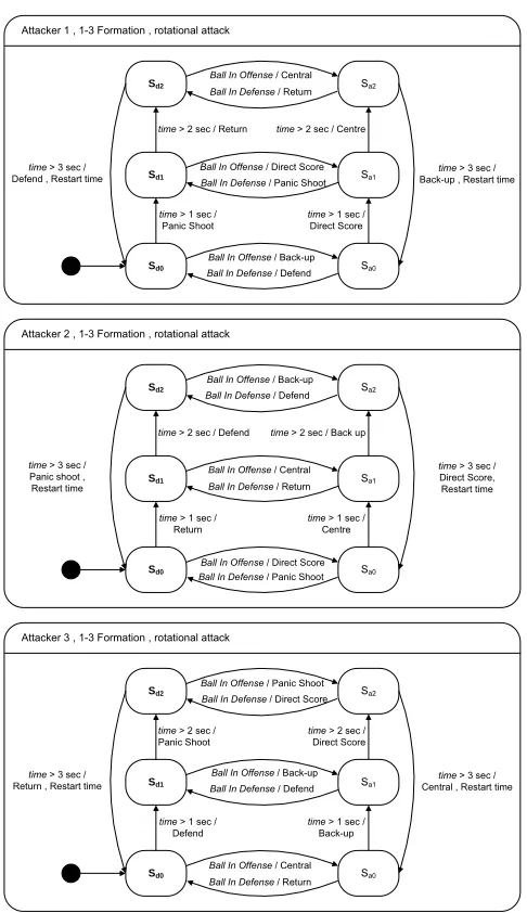
Figure 13 State diagrams of the attackers
In Figure 13, the behavior models of the attackers are shown; the attackers use a rotational way of attacking. Rotation is normally meant as the movement of an object in a circular motion. A rotational way of attacking means that the (positional) target points of the attacker are designed in such way that circular movement for the attacker is
seems to be enough time to reach a next target point. It has some attacking states Sa, when the ball is outside the defense area, and some defending states Sd, when the ball is inside the defense area.
In Table 9 the descriptions used in Figure 13 with their corresponding observations in Table 5 and their corresponding plans in Table 6 are shown.
Description Detailed Ball In Offense BALL_X > 0.25 Ball In Defense BALL_X <= 0.25
time > 3 sec ELAPSED_TIME >= 0.009090 time > 2 sec ELAPSED_TIME >= 0.006060
ConditionExpressions
time > 1 sec ELAPSED_TIME >= 0.003030 Central CENTRAL_ATTACKER
Shoot SCORE_DIRECT
Back-up BACKUP_ATTACKER Defend PEN_DEFENDER[3] Panic shoot PANIC_SHOOT
Plans
Return SIMPLE_DEFENDER[4]
Table 9 Description with their details
When in the attacking mode, the player moves cyclically through three important points, which are shown in Figure 14, and Figure 15. The attacker tries to shoot. After the shoot attempt, it positions itself in front of the opponent’s goal, returns to the back and positions itself at a back-up point. After that, it begins a new attack cycle.
Shoot Central
Back-up
Figure 14 Circular targets for the rotational attacker
Attacker 1 Attacker 2 Attacker 3
Time at 0 - 1 sec Back-up Central Shoot
Time at 1 - 2 sec Shoot Back-up Central
Time at 2 - 3 sec Central Shoot Back-up
Table 10 Different time-action combinations for different attackers, when the ball is in the offense
Figure 15 Singapore playing with 3 attackers
The attacking players can also help to clear the ball from the defense. In the defense, also a rotational behavior can be applied. Then the player moves cyclic through three important defensive points, which are shown in Figure 16.
Panic Shoot Defend
Returning
Figure 16 Targets for circular movement in defense
Attacker 1 Attacker 2 Attacker 3
Time at 0 - 1 sec Defend Return Panic shoot
Time at 1 - 2 sec Panic shoot Defend Return
Time at 2 - 3 sec Return Panic shoot Defend
Table 11 Different time-action combinations for different attackers, when the ball is in the defense
With the time-action combinations for the offense states (Table 10) and defensive states (Table 11) of the player, one can observe two important properties. First, when an
attacker in the defense has shot the ball outside the defense area, it will continue to shoot the ball. Second, when an attacker in the offensive performs the back-up action (the most back position in the attack cycle) and the ball enters the defense this attacker becomes the first helping defender. With these properties, a reasonably fast transition between offense and defense is being made. If one compares the plans that the attacker undertakes when the ball is in the defense, one can see a plan “Defend” which is also elaborated by the defender (section 3.2.2). Although the descriptions are the same, not exactly the same positioning is being realized for the different players.
In the behavior diagram for the attackers, one can conclude that when the attacker is in the offensive state, strategic plan generation only depends on time. However, the player execution of a strategic plan can depend on the position and speed of the ball. An example of such plan is a “Shoot”, which results in the creation of control signals that should let the robot intercept a (moving) ball and kick it towards some desired point. When one wishes to create a formation with the rotational tactic for 2 or 4 attackers; for 2 attackers, one could use other timing, but for 4 attackers one could add an additional plan to the behavior of the attackers, in order to prevent robot (players) producing the same plans at the same time.
3.3
Design of a 2-2 strategy
In the 2-2 strategy, the team is composed of players who perform the roles of keeper, defender or attacker. In this chapter, a 2-2 formation will be described, thus a strategy with 2 defenders, 2 attackers and a keeper.
During the EC 2006, all matches were lost to high scores. The offense had no possession because the defense was hardly to stop the scoring attempts of the opponents. By increasing our defensive capabilities, the goal is to create more
opportunities and time for creating offensive play. Therefore, a defensive approach after the EC 2006 was adopted focused primarily on performing saves on scoring attempts of the opponent’s teams. The defensive style of play is characterized as ‘low-pressure’. ‘Low pressure’ defense results in passive positioning in the back focused to prevent penetration of the defense and minimize chances for the opponent to out-dribble defenders.
3.3.1
The Keeper
The main task of the keeper is to stop the ball before the goal line. In addition, the main task for the defenders is to stop the ball before the keeper. Furthermore, the keeper tries sometimes to clear the ball away from the goal without losing the ability to return fast to its position in front of the goal line. The main idea behind the defensive approach was that it would be better to win with 0-1 than to loose with 21-10.
Figure 17 Successful clearing
In Figure 17, a filmstrip is shown when the keeper clears the ball. The keeper clears the ball only when the ball is next to the goal area. ‘Clear’-actions directed forward are not performed by the keeper to reduce situations in which the keeper is obstructed by own players. Because of the triangles in the corners of the field, a ‘clear’ action to the side can still cause the ball to move towards the offense.
Figure 18 Successful save
Figure 19 Maximizing goal coverage
In Figure 19, the defending robots are positioned such that the goal coverage is high. If the ball should suddenly move fast toward the goal, it is hoped that at least one of the robots will be on time to intercept the ball in front of the goal.
The behavior for the keeper used in the 2-2 using wings is the same as used by the 1-3 formation with the rotational tactic described in section 3.2.1.
3.3.2
The Defenders
In the 2-2 formation with ‘using wings’ tactic, the defenders adopt a low pressure style of defense. This means that the distances to the own goal are kept small. In a low-pressure style of defense, the distances to opponent players and ball are kept small. In Figure 20 the positioning of the defenders (robots 2 and 3) are shown and their small distances to the own goal. This is the positioning of the defense when no actual threat is detected.
Figure 20 Low pressure defense
shoot action by means of a PANIC_SHOOT when the ball enters the penalty area and the ball is not between the goal and the defender.
Figure 21 Defender taking offensive action
When the defenders do not deliberate upon an on-ball plan, they intend to plan the
PEN_DEFENDER, which drives the robot in straight lines around the goal area at some
distance, whilst keeping space for the goalkeeper to clear the ball as can be seen in Figure 17. The calculation of the desired position for the robot is shown in section A.3.1.
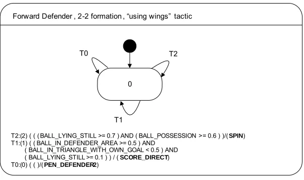
0
Forward Defender , 2-2 formation , “using wings” tactic
T2:(2) ( ( ( BALL_LYING_STILL >= 0.7 ) AND ( BALL_POSSESSION >= 0.6 ) )/( SPIN) T1:(1) ( ( BALL_IN_DEFENDER_AREA >= 0.5 ) AND
( BALL_IN_TRIANGLE_WITH_OWN_GOAL < 0.5 ) AND ( BALL_LYING_STILL >= 0.1 ) ) / ( SCORE_DIRECT) T0:(0) ( ( )/(PEN_DEFENDER2)
T2
T1 T0
Figure 22 State diagram for the forward defender
Transition name Rationale
T2 If the ball lies still against the robot, which is often a stuck ball situation, the robot should spin.
T1 If the ball is in the defense and not moving too fast and not between the robot and its goal, the robot will shoot.
T0 Default, the robot positions as the defender, which, is most far positioned from the goal, but still within the penalty area.
Table 12 Transitions with their rationale
3.3.3 The
Attackers
The attacker’s behavior is based upon the ball position. The left forward player, which is shown as robot number 5 in Figure 24 and Figure 25, is considered first. The behavior of the right forward, shown as robot number 4, is the same but mirrored along the length of the field. For the left attacker the ball’s position is classified to be in one of 4 areas, as shown in Figure 23.
Left Forward Right Forward
Left
Back Right Back
Figure 23 Quadrants for the left forward attacker
One area is left back, when the ball is behind 25% of the field length and in the left part of the field, shown in Figure 24. The second area is left forward, when the ball is in front of 25% of the field length and in the left part, shown in the left situation of Figure 25. The third area is right back when the ball is behind 37,5% of the field length and in the right part of the field. The fourth area is the when the ball is in front 37,5% of the field length and in the right part of the field, the right forward situation is shown in the right situation in Figure 25.
Figure 24 Attackers in passive stance
In Figure 24, the left forward attacker (robot 5) positions itself on 25% of the field length and 65% of the field width. If the ball is in the right back, the left forward attacker positions itself at 25% of the field length and 50% of the field width.
Figure 25 Attackers in the active stance
In Figure 25, two situations are shown. In the left situation, when the ball is in the left forward, the left forward attacker tries to shoot the ball by means of the plan
SCORE_DIRECT. The right attacker, positions between the own goal and the ball at a
distance of 600 mm behind the ball. This is done by means of the plan
BACKUP_ATTACKER.
In the right situation the roles are switched, the right forward attacker plans the
SCORE_DIRECT and the left forward the BACKUP_ATTACKER.
1 0
Left Forward Attacker, 2-2 formation , “using wings” tactic
T6:( 6 ) (( ( ELAPSED_TIME < 0.003030 ) ) / ( SCORE_DIRECT )
T5:( 5 ) ( ( ELAPSED_TIME >= 0.003030 ) ) / ( SCORE_DIRECT )
T4:( 4 ) ( ( BALL_LYING_STILL >= 0.4 ) AND ( BALL_POSSESSION >= 0.85 ) ) / ( SPIN )
T3:( 3 ) ( ( BALL_X < 0.25 ) AND ( BALL_Y >= 0.5 ) ) / ( REACTIVE_MOVE { x=0.25 , y=0.65 , theta=-3.14 } )
T2:( 2 ) ( ( BALL_X < 0.375 ) AND ( BALL_Y < 0.5 ) ) / ( REACTIVE_MOVE { x=0.25 , y=0.5 , theta=-3.14 } )
T1:( 1 ) ( ( BALL_X >= 0.375 ) AND ( BALL_Y < 0.5 ) ) / ( RUNUP_ATTACKER )
T0:( 0 ) ( ( BALL_X >= 0.25 ) AND ( BALL_Y >= 0.5 ) ) / ( SCORE_DIRECT ) T4
T3
T2 T1
T5
T6
T0
Figure 26 State diagram for the left forward attacker
In Figure 26, the state diagram of the left wing attacker is shown. The structure of the state machine of the right wing attacker is similar to the left wing attacker.
Transition name Rationale
T6
When the game is started, the attacker always starts with an attempt to score the ball. This is because an attacker is often positioned close to the ball during special game situations, for example a kick off.
T5 This transition is only to change the state of the attacker to normal play.
T4 If the ball lies still against the robot, the robot will spin. Such a situation is often a stuck ball situation.
T3
If the ball is left back, the defense has to get the ball to the offense and this robot positions itself in a position in front of the penalty area.
T2
If the ball is right back, the defense has to get the ball to the offense and this robot positions at a position in front of the penalty area. Notice the difference of conditions between T3 and T2 with regard to the BALL_X observation. This difference exists because if the ball is right forward, this player adopts the BACKUP_ATTACKER plan, which positions the robot behind the ball and the planning is careful with regard to getting too many robots in the penalty area.
T1 If the ball is right forward, the attacker takes a supportive role in the offense.
T0 If the ball is left forward, the attacker takes an active role in the offense and tries to shoot the ball into the goal.
Table 13 Transitions with their rationale
3.4 Evaluation
In the soccer game, offense and defense are separated by distinguishing two goals. The offense has as primary goal to move the ball into the goal of the opponent. The defense has as primary goal to prevent the ball entering their goal. When the ball is being moved from the own goal straight to the opponents goal it can be considered both offensively and as defensively beneficial.
On the other hand, there are also plans available with low offensive and defensive value: an example of such action could be standing still at the border in the middle of the field. A trivial example in a 5vs5 game is that of a team with all players staying still at the side borders. This team should already in offensive and defensive aspect be beaten by a team of two players with one keeper and an attacker which only pursuits the ball and tries to shoot directly at the opponents goal.
Next a look on how the 1-3 formation with the rotational tactic (§ 3.2) can be more offensive and more defensive than the 2-2 formation tactic (§ 3.3) is given.
Two players form the offense of the 2-2 formation, the first player controls the left half in front of the opponent’s goal and the second player controls the right half in front of the opponent’s goal. The offensive operates in the following manner: first, when the ball is on the left part, the first player tries to shoot the ball toward the opponent’s goal. The second player is moving at a point behind the ball. Furthermore, the second player starts
With this strategy, always a player tries to shoot the ball when the ball is in front of the opponent’s goal.
Unfortunately, shoot attempts can result in situations in which the player completely misses the ball. This is where the 1-3 formation with the rotational tactic (§ 3.2) becomes more offensive. The 1-3 formation is able to generate more shoot attempts per second than the 2-2 formation (§ 3.3). Furthermore, this strategy also returns robots that
attempted to shoot, to positions behind the ball, which are supposed to be more favorable when shooting, toward the opponent’s goal, starts. For shooting in the defense the same argument holds, furthermore most of the time 3 robots are positioned in the penalty area while in the 2-2 formation most of the time 2 robots are positioned there because the other defender robot attempts to shoot the ball, misses and drives somewhere else. This is illustrated in Figure 27; robot 1 is the keeper, robots 2 and 3 are defenders and robot 4 and 5 are the attackers.
Figure 27 Defenders 2 and 3 missed the ball
Both strategies have been used during the EC 2007. In matches played against VSB-TUO from the Czech Republic, the 1-3 Formation was indeed more effective than the 2-2 formation. In matches against TUKE robotics with the 1-3 formation more pressure to the ball could be kept, but our transition from offense too defense was to slow which caused a higher change of success for long dribbles (for the TUKE) because in our defense only one defender was present. This could be solved by adjusting the Back Up position more to the back. However, in matches against TUKE robotics the difference of effectiveness between the two strategies was not easily observable. Mainly, because the ball
2-2 formation
zone based offense rotational tactic 1-3 formation
Advantages Efficient against long dribbles. Able to recover from failed shoot attempts.
Disadvantages Low pressure on the ball. Vulnerable for long dribbles from the opponent.
Table 14 (Dis) advantages of the different strategies
4 Underlying
systems
This chapter describes additional modification to the MI20 system, used to provide the Strategy module with consistent information and adequate control signal calculation.
4.1 Robot
identification
Robot identification was improved by altering the Vision module. By using different color patches, as seen in Figure 28, direct identification of the robots on the field is possible.
green
Figure 28 Different color area arrangements for the color patches
Before robot identification is explained, some terms are explained:
Blob
A blob is a data structure that contains the position information of the barycenter of a recognized color area on the soccer field. The color segmentation [20] in the vision module determinates the blobs that consist of clusters of adjacent pixels with similar color.
Blob combination
A blob combination is a tuple, with a green blob, pink blob and a team color blob.
Match function
The match function calculates a value that represents the correspondence of a given blob combination with a given color patch.
To recognize a certain color patch two steps are taken:
Step 1:
For each blob combination, the matching, in terms of an error value, is calculated. The blob combination with the minimal error is selected.
Step 2:
From the selected blob combination, the centre and the orientation is determined.
This approach has as disadvantage that wrong blob combinations can be associated with a certain color patch. Different patches positioned against each other can cause such a wrong association.
Another method for patch recognition could use least squares fitting.
4.2 Motion
caused frequent request of re-planning for the motion module. The proactive motion module could not adequately handle re-planning and the robots showed slow speeds and response.
4.2.1
Proportional Cosine control
With proportional cosine control [17] the linear velocity is proportional to the distance error d. Also the angular velocity is proportional to the angular error θe. See Figure 29.
Figure 29 Cosine control
The following equations show the determination of the linear and angular velocities.
Vlin = Kp · d · cos(θe) + vc
Vang = Kθ · θe
Kp and Kθ are called the proportional and angular gain, and are constant. vc is a small
constant velocity which can be used when we want to move the robot through some point instead of stopping at the goal position. This can be the case when a robot is moving towards an intermediate point in a planned path.
To help understand the working of these control law equations, consider the robot being oriented away from the target point g, with θe± ½π . In this situation, the linear velocity is limited by the cosine and a large angular velocity is calculated. In contrast, when the target point is in front of the robot and the angular error θe is small, the linear speed can reach its maximum height. The values for the gain are set to Kp=0.3 and Kθ=8.0.
Determination of proper values and also the influence of dead time to the use of a proportion cosine controller should be investigated further.
The problem encountered with the proportional controller is that one has 2 options:
• High gains:
Results in fast speeds for short targets, but in case of for greater distances unrealistic control signals.
• Low gains:
Results is realistic control speeds for greater travel distances, but too slow speeds for short distances.
4.2.2
The pursuit move function
In the pursuit approach [18] the main idea is to travel circle wise through the goal point
gv, as seen in Figure 30. To accomplish this, the curvature of the circle is calculated and from the curvature the control signals (
ω
and v ) are obtained. The curvature C of aThe calculation of the control speeds involves different steps:
Step 1:
Transform the goal point to robot coordinates. The transformed target is called gv with coordinates (ygv, xgv)
Step 2:
An appropriate circle arc, with a certain radius r, is determined for the robot to travel. The aerial distance D from the robot to gv is given by:
2 2
gv gv
D
=
y
+
x
The curvature C, which determines the ratio between
ω
and v. C defines the desired circle arc, and is given by:2
An adequate linear speed v is calculated. Default the maximal linear speed, geared by the system user, is used. However, when the robot has to stop at the given goal point, the linear speed is reduced as the robot comes closer to the goal point. This speed is limited by a factor s, which is made dependant on the squared distance as follows:
2 and the robots stops. On the other hand, when D2 is great s approaches the value 1 and the linear speed is almost not limited.
An adequate angular speed ω is calculated. As long as the robot has not reached the goal point, the angular speed is calculated according to the linear speed and the radius of the circle. Otherwise, the angular speed is calculated to pose the robot to a given orientation.
Step 5:
The last step involves slippery