Western University Western University
Scholarship@Western
Scholarship@Western
Electronic Thesis and Dissertation Repository
7-25-2018 10:30 AM
Engineering Graphene Oxide-based Nanostructures for DNA
Engineering Graphene Oxide-based Nanostructures for DNA
sensors
sensors
Aditya Balaji
The University of Western Ontario
Supervisor Zhang, Jin
The University of Western Ontario
Graduate Program in Biomedical Engineering
A thesis submitted in partial fulfillment of the requirements for the degree in Master of Engineering Science
© Aditya Balaji 2018
Follow this and additional works at: https://ir.lib.uwo.ca/etd Part of the Biomaterials Commons
Recommended Citation Recommended Citation
Balaji, Aditya, "Engineering Graphene Oxide-based Nanostructures for DNA sensors" (2018). Electronic Thesis and Dissertation Repository. 5492.
https://ir.lib.uwo.ca/etd/5492
Abstract
Various nanostructures have been explored in DNA biosensors to convert the hybridization of
DNA sequences to easily measurable processes, including optical, mechanical, magnetic, or
electrochemical process. In this thesis, graphene oxide, a two-dimensional nanostructure, is
applied in quenching the fluorescence of core-shell nanoparticles modified with targeted DNA
sequences. The core-shell nanoparticles, iron oxide (Fe3O4) core, and fluorescent silica (SiO2)
shell, were produced through a wet chemical process which can directly link to a targeted DNA
sequence (DNA-t), and the graphene oxide nanosheets were produced by the oxidation of
graphite. In the meantime, a complementary- DNA single strand (DNA-c) is designed to interact
with graphene oxide. Two different mechanisms have been investigated in the sensing system;
(1) Ionic interaction between the DNA sequences and nanostructures through cationic bridging;
and (2) covalent binding between the DNA sequences and nanostructures. In the cationic bridge
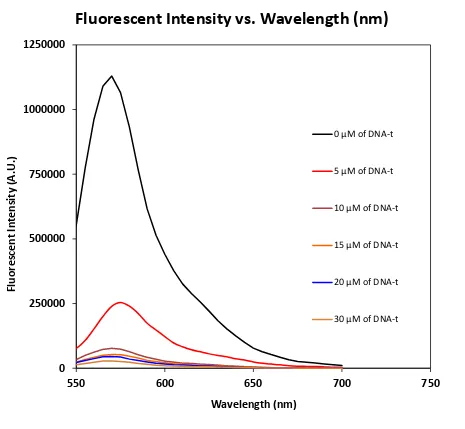
system, the fluorescence intensity changes with the concentration of DNA-t in the range of 0 to
30 µM with the limitation detection at 0.25 µM without graphene oxide; the other system can
detect DNA-t in the range of 0 to 4 µM with limitation detection at 0.41 µM. In addition, the
effect of concentration of graphene oxide on the fluorescence intensity of core-shell
nanoparticles has been investigated.
We hope that the the validation strategy by engineering the two dimensional nanostructured
system can be further applied towards more efficient Cancer diagnosis.
Keywords
Co-Authorship Statement
Chapter 1(Introduction), Chapter 2(Background and literature review), Chapter 3(Experiment
Procedures) Chapter 4 and Chapter 5 include two different design methods towards DNA
sensing from the multifunctional nanomaterials. Chapter 6 concludes with the future perspectives
and conclusion. These chapters were written by Aditya Balaji with the assistance of Professor Jin
Acknowledgments
I would like to thank several people for their guidance towards my research project and my thesis
would not have been accomplished without the gratitude from them. I would like to acknowledge
all of them.
Firstly, I would like to give a big gratitude to my supervisor Dr. Jin Zhang for her guidance and
support for my research project. The opportunities starting from the NSERC USRA scholarship
helped me elevate my interest in the engineering research that Dr. Zhang provided me, which
lead to my graduate work in Biomedical Engineering. Dr. Zhang’s support, enthusiastic
guidance, support, trust and understanding on a daily basis helped me fulfill the fundamentals of
how research unfolds which I can utilize in the future for research and development prospects.
Secondly, I would like to thank my advisory committee: Dr. Andy Sun and Dr. Jeff Carson for
their guidance and feedback throughout the whole duration of my project.
Thirdly, I would like to thank the members of the Biotron facility, Dr. Richard Gardiner and Mrs.
Karen Nygard for their assistance in using the respective equipments associated in the facility.
Next, I would like to thank all the members in the research group: LongYi Chen, Andrew Tse,
Songlin Yang, Denghuang Zhang, Yang Che, Yingqi Zhang, and Eugene Hwang for the
continuous support, encouragement and the good times we had over the duration of my project.
Lastly, I would like to thank my family for their continuous support, encouragement throughout
my life which helped me finish the thesis.
This work has been supported by the Natural Science and Engineering Research Council of
Table of Contents
Abstract ... ii
Co-Authorship Statement... iii
Acknowledgments... iv
Table of Contents ... v
List of Figures ... ix
List of Abbreviations ... xii
Chapter 1 : Introduction, Motivation, and Objectives ... 1
1.1 Brief Overview of Nanotechnology ... 1
1.2 Fluorescent Magnetic Core-shell Nanostructures ... 1
1.2.1 Fluorescent Shell Structures ... 2
1.2.2 Magnetite Core Structures ... 2
1.2.3 Role of Magnetic Structures in DNA Sensing ... 3
1.3 Applications of Fluorescent Magnetic Core-shell Nanostructures ... 3
1.3.1 Imaging ... 3
1.3.2 Biosensor... 4
1.4 Challenges Faced with Nanostructured Biosensor ... 4
1.5 Surface Modification of Nanostructures ... 5
1.6 Graphene and Graphene Oxide Derivatives ... 6
1.7 Motivation ... 7
1.8 Thesis Overview... 9
1.9 References ... 11
Chapter 2 : Literature Review ... 20
2.2.1 Electrochemical Biosensors ... 22
2.2.2 Optical Biosensors ... 23
2.2.3 Mass- Sensitive Devices ... 24
2.2.4 Magnetic Biosensors ... 24
2.3 Different Techniques Used in Different Biosensors ... 25
2.3.1 Graphene-DNA Electrochemical Sensor for Target DNA Detection 25 2.3.2 FRET and CRET in Optical Sensors ... 27
2.3.3 DNA Hybridization with Mass-Sensitive Devices ... 28
2.3.4 Magnetic Tunnel Junction Sensors on DNA Detection With Magnetic Nanoparticles ... 29
2.4 The Different Nanostructures Used in Biosensors ... 29
2.4.1 Iron Oxide Nanostructures ... 30
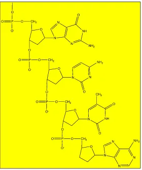
2.4.2 The Idea Behind Deoxyribonucleic Acid (DNA) ... 32
2.4.3 Graphene Oxide and Graphene ... 34
2.5 Future Perspectives and Summary ... 36
2.5.1 Future Perspectives ... 36
2.5.2 Summary ... 37
2.6 References ... 37
Chapter 3 : Experimental Methods ... 46
3.1 Synthesis of Magnetite ... 46
3.2 Synthesis of Core-Shell Structure ... 47
3.3 Synthesis of Graphene Oxide ... 50
3.4 Target-Probe DNA Loading on Iron-Core Shell Particles ... 51
3.5 Capture-Probe DNA Loading on Graphene Oxide ... 51
3.8 Amino Modification of Silica Particles... 52
3.9 Glutaraldehyde- Amino Modified Iron Oxide Silica Particles ... 53
3.10 DNA-t-Glutaraldehyde-Amino Modified Iron Oxide Silica Particles ... 53
3.11 5’ Mod DNA-c Loading on Graphene Oxide ... 53
3.12 Characterization Methods ... 55
3.13 Transmission Electron Microscopy ... 55
3.14 Fourier Transform Infrared Spectroscopy ... 55
3.15 Ultraviolet-visible Spectroscopy ... 55
3.16 Vibrating Sample Magnetometer ... 56
3.17 Fluorescence Spectroscopy ... 56
3.18 References ... 56
Chapter 4 : Development of Multifunctional Nanoparticles for DNA Sensing Using the Charging Effect ... 59
4.1 Introduction ... 59
4.2 Results ... 60
4.3 Characterization of Fe3O4 Nanoparticles ... 61
4.5 Fourier Transform (FTIR) Analysis ... 66
4.6 Vibrating Sample Magnetometer Analysis ... 69
4.7 UV Absorption Tests for DNA-c Conjugated on Graphene Oxide ... 71
4.8 Fluorescent Studies and Analysis... 72
4.9 Summary ... 79
4.10 References ... 79
Chapter 5 : Development of Multifunctional Nanoparticles for DNA Sensing Using Covalent Bonding ... 81
5.3 Fourier Transform Infrared Spectroscopy Analysis ... 86
5.4 Fluorescent Studies ... 96
5.5 Fluorescent Intensity Levels with Different Concentrations of GO ... 98
5.5 Summary ... 100
5.6 References ... 100
Chapter 6: Summary and Future plan ... 101
6.1 Summary ... 101
6.2 Future Plan ... 102
Appendices ... 104
Curriculum Vitae ... 105
List of Figures
Figure 2.1: Electrochemical Design for DNA-t Detection [7] ... 26
Figure 2.2: Oxidation and Reduction of Iron Oxide Compounds [62] ... 31
Figure 2.3: Structure of DNA ... 33
Figure 2.4: The Structure of Bases in a and b ... 33
Figure 2.5: Graphene Oxide Structure ... 35
Figure 2.6: The Structure of Biotin [82] ... 36
Figure 3.1: Iron Oxide Silica Structure ... 49
Figure 3.2: The Structure of the Hummer’s Approach [5] ... 50
Figure 3.3: The Functional Groups Associated with Graphene Oxide ... 51
Figure 3.4: 5’ Mod DNA Structure ... 54
Figure 4.1: TEM Micrograph Image of the Iron Oxide Nanocrystals ... 62
Figure 4.2: TEM Image of the Core-Shell Structures ... 64
Figure 4.3: TEM Image of the Core-Shell Structures ... 65
Figure 4.4: FTIR Spectrum of Fe3O4 Nanocrystals... 67
Figure 4.5: FTIR Spectrum of Fe3O4@SiO2 Multifunctional Nanostructures ... 68
Figure 4.6: FTIR Spectrum of Fe3O4@SiO2@DNA-t ... 69
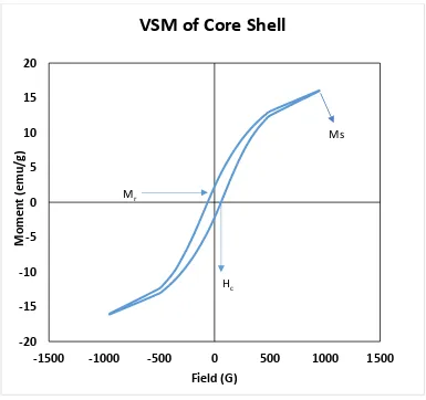
Figure 4.7: VSM of Iron Oxide Nanocrystals ... 70
Figure 4.9: UV Absorption of DNA-c on GO and GO ... 72
Figure 4.10: The Fluorescent Intensity of DNA-t on Iron Oxide Silica (Core-Shell) Nanostructures ... 73
Figure 4.11: Fluorescent Intensity vs. DNA-t Concentration ... 74
Figure 4.12: Fluorescent Intensity vs. LOG (DNA-t) ... 75
Figure 4.13: The Fluorescent Intensity on The Effect of GO ... 76
Figure 4.14: Fluorescent Intensity vs. GO Concentration ... 77
Figure 4.15: Fluorescent Intensity vs. LOG GO [M} ... 78
Figure 5.1: 5’ Modification of DNA ... 83
Figure 5.2: Imine Reaction of Amine to Glutaraldehyde ... 84
Figure 5.3: Imine Reaction of the 5’ Mod DNA to Glutaraldehyde ... 85
Figure 5.4: FTIR Spectrum of Fe3O4@SiO2 ... 88
Figure 5.5: FTIR Spectrum of Fe3O4@SiO2@NH2 ... 89
Figure 5.6: FTIR Spectrum of Glutaraldehyde ... 90
Figure 5.7: FTIR Spectrum of Fe3O4@SiO2@NH2@Glu ... 91
Figure 5.8: FTIR Spectrum of Fe3O4@SiO2@NH2@Glu@DNA-t ... 92
Figure 5.9: FTIR Spectrum of GO ... 93
Figure 5.10: FTIR Spectrum of DNA-c ... 94
Figure 5.11: FTIR Spectrum of DNA-c on GO ... 95
Figure 5.13: Fluorescent Intensity with Different 5’ Mod DNA Concentrations ... 97
Figure 5.14: The Effect of GO on the Fluorescent Intensity of Fe3O4@SiO2@NH2 with DNA-c
Hybridized on DNA-t ... 98
List of Abbreviations
Ab - Antibody
AFM - Atomic Force Microscopy
Anti CRP - Anti C-Reactive Protein
APTES - Amino-propyl-tri-ethoxy-silane
BRCA - Breast Cancer
C.E. - Counter Electrode
CL - Chemiluminescence
CRET - Chemiluminescence Resonance Energy Transfer
CRP - C- Reactive Protein
CT - Computed Topography
CTAB - Cethyltrimethylammonium Bromide
C.V. - Cyclic Voltammetry
CVD - Chemical Vapour Deposition
DNA-c - Complementary- Deoxyribonucleic Acid
DNA-t - Target- Deoxyribonucleic Acid
EDC - 1-Ethyl-3-dimethylaminopropylcarbodiimide
EIS - Electrochemical Impedance Spectroscopy
fcc - Face Centered Cubic
FL - Fluorescence
fM - femtometer
FRET - Fluorescence Resonance Energy Transfer
FT-IR - Fourier Transform- Infrared Spectroscopy
G - Gaussian
Glu - Glutaraldehyde
GO - Graphene Oxide
GPa - GigaPascal
HCl - Hydrochloric Acid
kDa - kiloDaltons
MDEA - N-methyl- diethanolamine
mK - MegaKelvin
Mr - Remanence Magnetization
MRI - Magnetic Resonance Imaging
mRNA - Messenger Ribonucleic Acid
Ms - Saturation Magnetization
NHS - N-Hydroxysuccinimide
PPi - Pyrophosphate
PTT - Photo-thermal Therapy
PVD - Physical Vapour Deposition
QD - Quantum Dot
R.E. - Reference Electrode
RITC - Rhodamine B Isothiocyanate
RNA - Ribonucleic Acid
SEM - Scanning Electron Microscopy
SPION - Superparamagnetic Iron oxide Nanostructures
SPR - Surface Plasmon Resonance
T2 - Transverse 2
TEOS - Tetraethylorthosilicate
TPa - TeraPascal
VSM - Vibrating Sample Magnetometer
UV - Ultra-Violet
W.E. - Working Electrode
Chapter 1 : Introduction, Motivation, and Objectives
1.1
Brief Overview of Nanotechnology
Nanotechnology is defined as the manipulation of matter on the atomic or molecular level where
the design is used for an application. The structures are worked between 1 nanometer and 100
nanometers in size. It refers to developing structures by top-down or bottom-up processes of
individual components. [1,2] From the definition, it acts on the emerging technologies associated
with the novel classes of therapeutics. Using the improved technology of nanotechnology, it may
be possible to improve upon Targeted Drug Delivery [3], Detection [4], Medical Instrumentation
[5] and other specific areas. Many materials will be acted upon where the nanomaterial being
used has a large surface area to volume ratio and is size dependable for many applications as
stated above.
1.2
Fluorescent Magnetic Core-shell Nanostructures
Nanostructures exhibiting both magnetic and luminescent properties are used towards many
biological applications. Nanomaterials with bifunctional properties such as luminescence and
magnetism, can be used in a wide range of applications such as high-contrast bio-imaging,
early-stage diagnostics, and more efficient therapeutics. The growing potential of the bifunctional
nanomaterials have enhanced the likelihood of nano bio-interaction, protecting the core from
aggregation, and improving the stability of the nanostructures. Silica, which is shown as the
inorganic core is a good non-cytotoxic and biocompatible material which has been shown to
provide some prime advantages for nanoparticles. The silica shell can decrease the polydispersity
of the particles to prevent flocculation of particles, thus producing a greater stability in biological
buffers. Second, it minimizes the oxidation from the magnetic core helping to maintain the
physical and chemical properties. Third, silica can be used to surface modify with other
functional groups to enhance the application in the field of study. Having silica surrounding the
1.2.1 Fluorescent Shell Structures
Magneto-fluorescent particles have been recognized as the cutting edge materials for biological
applications. Size and morphology has become a challenge in synthesizing magneto-fluorescent
nanomaterials that exhibit uniform and tunable sizes, high magnetic moment, and maximized
fluorophore coverage. To fully cover the potential of fluorescent shell structures for their optimal
performance, the design criteria has to be fulfilled: uniform and tunable sizes, high magnetic
content loading for magnetic properties, maximum loading of the fluorophore at the surface for
an optimal fluorescence signal, long-term colloidal stability and a versatile surface functionality
for the varied requirements of different applications in the biomedical sector. [10,11]
1.2.2 Magnetite Core Structures
Magnetite Core Structures possesses the chemical composition Fe3O4 where its unique properties
and applications are studied upon in the area of nanotechnology. Different syntheses processes
are involved to control the sizes for scientific and technological interest. [12,13] Fe3O4 has a
cubic inverse structure with oxygen forming a fcc closed packing where Fe cations adhere two
oxidation states of Fe+2 and Fe+3. [14] When the Fe cation is in a +2 state, the cation state can
achieve an octahedral and a tetrahedral state. As opposed to the state of +3, it only has one state
which it adheres, which is the octahedral state. The electrons move around the two oxidation
states in the octahedral state. From the different applications ranging from MRI Imaging to
Bio-sensing, it has its advantages and disadvantages which can be improved upon. The advantages of
using magnetic nanostructures in various applications are that they are chemically stable under
physiological conditions [15], low in toxicity [16], and have a good magnetic moment which
corresponds to the good magnetic properties it consists. [17] The disadvantages of using these
magnetic nanostructures in these applications are that the particles aggregate [18], have a poor
water solubility [19], and a low cellular uptake efficiency. [20] Due to the intrinsic instability
over periods of time, efforts of surface modifying the core structure is being done to minimize
the instability through gravitational force, avoid strong interaction and aggregation of the
nanostructures. [21]
but one of the conventional methods for the simplest and cheapest process is to imply the
precipitation technique. The size is dependable on the various properties as a small size in shape
implies a high surface-area-to-volume ratio which interacts with various types of chemical
species, both aqueous and gaseous. The controlled factors associated with the shape, nucleation,
growth, durability, reproducibility, scalability, dispersibility play a key role for building complex
nanostructures. Magnetic enhancement can be achieved by tailoring the diameter of the coated
iron oxide NP with the adjustment of the reduction and repeated time. Surface
chemistry/modification can be specific to certain biomedical applications making it more cell
internalized, biocompatible, lipophilic, etc. [22-25]
1.2.3 Role of Magnetic Structures in DNA Sensing
The use of magnetic structures demonstrates bifunctional properties that can be used to improve
their biocompatibility, and stability. The functionalization of silica surrounding the core structure
is one prime example that allows the attachment towards the target DNA as a better sensing
technique.
Magnetic nanoparticles owe their popularity to their numerous attributes such as their magnetic
properties that enable them to be directed by an external magnetic field, the possibility to
separate them from a reaction mixture, in addition to their low toxicity and biocompatibility. The
magnetic properties of magnetite can help separate the multifunctional particles from the target
DNA to study the quantification aspect of the target DNA. The role of magnetite also helps in the
kinetics of hybridization of oligonucleotides. [24,25]
1.3 Applications of Fluorescent Magnetic Core-shell
Nanostructures
1.3.1 Imaging
One of the major applications (SPIONS) take place in Imaging [24-27]. In MRI imaging, these
magnetic structures act on T 2 acquisitions where it can be used for better contrast imaging.
[27-29]. For better contrast imaging, nanoparticle surfaces can be conjugated with targeting species
Reduction in material needed to achieve a set contrast, long blood-pool residence times, ability to
undertake single cell tracking, reduced toxicity making it biocompatible. The precision control
over size, shape and architecture has an impact in the physical attribute to determine their ability
to provide contrast, i.e. ability to interact with the external magnetic field. [30]
One other area this technology can be used is in fluorescence imaging. The surface modification
on the multifunctional nanostructures play a vital role on the ability to determine their ability to
fluoresce. By having the ability to image fluorescent nanostructures, the species can be detected
that are not amenable to direct fluorometric imaging (such as pH, concentration, etc.) [31]
1.3.2 Biosensor
Starting with the definition of a biosensor, it is a small device which targets a specific analyte. It
contains three components to be a functional device. First, there has to be a biological
component that attaches to the analyte ,which couples to a form of transducer where the signal
processor outputs the information. One of the most utilized methods is the fluorescence-based
detection due to its high sensitivity, simplicity, and diversity. The advancements of
nanotechnology using bifunctional nanomaterials have opened up to new horizons for
fluorescence detection. The absorption as well as the luminescence peaks can be controlled to the
particle size and size distribution based on the type of method. The advantages associated in
bio-sensing: (1) silicon is abundant and non-toxic; (2) high surface-to-volume ratio of the
nanoparticles facilitates their binding to biomolecules; (3) the inclusion of the fluorescent dye
inside each nanoparticle results in excellent photo-stability due to the shielding effect of silica
from molecular oxygen, leading to high signal amplification factors during detection; (4) silica
allows for further functionalization for a wider range to see the control in the fluorescence on the
selectivity and sensitivity. [32-34]
1.4 Challenges Faced with Nanostructured Biosensor
Nanostructured materials provide an effective surface of biomolecule immobilization for the
transducer to recognize the signal. The properties from the bi-functional materials provide an
interesting platform for interfacing bio recognition elements with transducers for signal
effective surface area, functionality, adsorption capability have to be taken into consideration.
Current challenges associated with the magnetic- based nanotechnology in nanostructured
biosensors are how to control precisely the morphology and monodispersed size of the
nanoparticles to obtain high quality signals. The conformational changes of the biological agent
and analyte could lead to discrepancies in understanding the signal. Larger targets that adhere to
the analyte could be replaced due to a larger surface area and more functional groups in pursuing
the interest from the transducer. The selectivity and specificity is another area that is in need of
improvement where the suitable interface could be optimized. Another challenge that needs to be
faced is the reproducibility which depends on the stability of the bio-receptor and the fabrication
of the biosensor itself. Novel improvements can advance the technology, but the uncertainty is
unavoidable, and always a great challenge. The calibration in some biosensors have to be done
for every measurement and could be avoided if the samples are conducted in similar biological
environments. To minimize the measurement uncertainty, it is crucial to use similar medium
conditions for both standard calibrations as well as for the sample. Regeneration is another
challenge where some sensors have a difficulty in being re-used. The complex immobilization
can deteriorate the biosensor from being used multiple times and improvements are still sought
out in the future. Signal enhancement is another proposed area where challenges are sought out.
Reaction conditions such as pH and temperature can hinder the signal amplification causing a
discrepancy. [35-37]
1.5 Surface Modification of Nanostructures
Surface Modification refers to modifying the surface of the material where properties associated with physical, chemical and/or biological characteristics differ from the original surface material.
[38] Some of the prime characteristics that change upon modification include: roughness, cell
internalization, lipophilicity, aggregation, surface charge, biocompatibility and reactivity. [39]
Surface Modification can be sub categorized into two processes: Top-down Process and
Bottom-Up Process. Both of these processes are used in nanofabrication. [40]
The top-down approach is characterized by the synthesis of the etching out of crystal plane
bigger piece in a self structuring process and fabricated to the particular design. The advantages
associated with the top down approach would be the cost, better control and scalability.
Two processes that are characterized under the top-down approach: Physical Vapour Deposition
(PVD) and Chemical Vapour Deposition (CVD). [41] In physical vapour deposition (PVD), the
particles will be transformed from a solid to a gaseous state, either through the thermal
evaporation process or through resistive etching. The ejected molecules will travel from the
target to the substrate and form the thin film. The bombardment of ions takes place where the
kinetic energy is about 1-10 eV. [42-49] In Chemical Vapor Deposition (CVD), the material will
be in a gaseous state which later condenses on the substrate through chemical precursors. There
are advantages associated with the CVD process where it can enhance the hydrophilicity by
increasing the functionality of the molecule. This process depends on the surface chemistry as
the precursors involved can be toxic.
The limitations associated with the top-down approach is from the UV light where the small
wavelengths become deleterious to the material. [50-60]
A bottom up method is the process of stacking atoms onto the substrate. [58] The small buildup
of atoms happens to be crafted through covalent or supramolecular interactions. [58-59] The self
assembly process undergoes an ordered process through various supramolecular interactions (i.e.
hydrogen bonding, van der waals, electrostatic, pi-pi interactions, hydrophilic-hydrophilic, and
hydrophobic-hydrophobic interactions). The bottom-up approach technique is one of the
processes involved in biological applications. [59-62]
1.6 Graphene and Graphene Oxide Derivatives
Graphene is an allotrope of carbon which forms a 2D, atomic scale hexagonal lattice and it is
able to effectively conduct heat and electricity. The shape is made up of a hexagonal lattice of
carbon atoms in a honeycomb structure. It is made out of carbon atoms where each atom
consists of four bonds, three sigma bonds and one pi bond out of the plane. The stability of the
material is dependent on how tightly packed carbon atoms are from the sp2 hybridization. [63]
Fascinating properties of graphene arise from its high surface area combined with electronic and
area-to-volume ratio and high conductivity, it leads to significant improvements in many applications.
[63]
Due to its unique microstructures, graphene demonstrates special and always enhanced
physiochemical properties. For instance, the Young’s modulus and the intrinsic strength of
graphene are around 1 TPa and 130 GPa respectively. The electron mobility and thermal
conductivity of graphene are 2.5 × 105 cm2 V-1 s-1 and 3000 W mK-1 respectively. [64] Graphene
has been used to fabricate flexible electronics [65], high-frequency and logic transistors. [66]
Recent studies show that graphene can be applied in electrochemical and optical biosensors to
detect small levels of cancer biomarkers. [67]
Hummer’s approach is the most common one for the synthesis of graphene sheets from graphene
oxide. [68-71] The reduced form of graphene oxide is graphene through an oxidizing agent, like
hydrazine or ascorbic acid. Overall, using Hummer’s approach is one of the best methods in
producing both of these compounds.
The oxygen functional groups on the surface of graphene oxide (GO) provide good sites for a
myriad of interactions for linking molecules such as polymers, nanoparticles (NPs), etc. In GO,
the associated functional groups are epoxy bridges, hydroxyl and carboxyl groups. Due to the
disruption of sp2 bonding, it acts as an electrical insulator. The advantages of using GO for
enzyme immobilization induces many explorations of its properties and applications where
techniques, such as Atomic Force Microscopy (AFM) and Scanning Electron Microscopy (SEM)
could be used to view the immobilized structure. [72-77]
1.7 Motivation
DNA sequencing is the process of determining the precise order of the nucleotides. It determines
the order of the bases in a strand of DNA. The knowledge of DNA sequences has become
indispensable in basic biological research, and applied in applications in medical diagnosis,
biotechnology, forensic biology, and biological systematics. DNA sequencing is the standard
method utilized for initial identification of mutations. People study the DNA sequences for
serve as a reliable biomarker for the detection of Cancer as well and many methods are in place.
[78-79]
The main methods researchers are working on in DNA detection are using the polymerase chain
reaction (PCR), radioisotopes, intercalating dyes exposed with UV light, and silver staining
process.
The first method involving PCR is a powerful tool to analyze samples of DNA sequences apart
from amplifying minute amounts of nucleic acids. The drawback associated with PCR is that it is
not only a very sensitive technique, but also specific. The primers have to be directly
complementary to the target DNA for DNA sequencing detection and amplification. As the
technique is too specific, it can cause false negative results. [80,81] Using radioisotopes by
incorporating P32 into one of the dNTP can be dangerous, expensive and a long time for the
detection to occur. [82,83] The third method of intercalating dyes exposed to UV light will label
DNA but not differentiate between different amplicons. [84] The fourth method involves the
silver staining process can result in poor images from the high background noise and the expense
of the reagents. [85]
From these shortcomes from these primary methods, the use of the fluorescent detection is a
good approach for its low cost, high sensitivity, and low background noise. In particular, DNA
offers a number of potential advantages for use in this setting. One is water solubility where it is
highly soluble in biological settings, while achieving the water solubility is a challenge for small
molecules. Second is the ease of synthesis where it could be bounded to fluorescent tags and
quenchers. With all the advantages associated, the fluorescence detection is one of the ways that
leads to the objective of my thesis.
Materials like gold and quantum dots have been utilized for the application of DNA biosensors.
This project revolves around the use of nanomaterials in two different mechanisms and see the
sensitivity of the target DNA.These magnetic nanoparticles are technologically challenging to
control the size, shape, stability, and dispersibility in desired solvents. The magnetic iron oxide
NPs have a large surface-to-volume ratio where the major drawbacks of using only the core
Covalent Interaction System. The cationic bridge system involves using a cationic molecule to
bridge the interaction between the DNA with silica particles as well DNA-c on GO. The DNA
gets hybridized in solution to study how selective and sensitive it is towards DNA using an
optical sensor and study the effect of GO. Second, the covalent interaction involves modifying 5’
DNA-t and interacting it with the silica particles. DNA-c will also be modified where it interacts
with the COOH on GO. The DNA will be hybridized in solution and the DNA-t on silica
particles at different concentrations will be studied upon.
The objectives of this thesis:
• The synthesis of Iron Oxide nanostructures (Formation of the Core): (1) First process delves into the chemical synthesis; (2) Second process delves into the coating process of
the inorganic core on iron oxide; (3) Third process involves for further functionalization
onto the inorganic core.
• The synthesis of the Graphene Derivatives and further functionalization onto the material
• To compare the characterization of Iron oxide and the core-shell using Vibration Sample
Magnetometer(VSM), Transmission Electron Microscopy(TEM)
• To compare the DNA adsorption on the two different systems by looking at various characterizations as well on the effect of graphene oxide
1.8 Thesis Overview
Chapter 2 Literature review
This chapter outlines the applications revolving around iron oxide and the functionalized uses of
this material in the biomedical industry. The advantages of iron oxide when functionalized
produces better properties associated with better sensitivity and selectivity due to the magnetic
properties associated with the core material. The advantages associated with the material are
introduced to show how early it can detect the biomarker activity and act as a better biosensor.
The idea of what a typical biosensor is introduced to apply how early cancer tumor cells can be
detected. Also, the problems associated with just iron oxide is encountered to see the difference.
Different functionalized materials are discussed in the chapter and various surface modification
Chapter 3 Experimental procedure
This chapter outlines the experimental procedure for the different synthetic procedures of the
core and the shell. Also, in addition, the process to synthesize the derivatives of graphene is also
shown. In addition to this, various characterization techniques are observed in this research to
later observe the DNA adsorption onto the functionalized material for application use. The two
different mechanisms of the Cationic Bridge System and Covalent Interaction System adhere to
different synthetic processes which are explained. Different synthetic procedures are put in place
to explain the two different mechanisms which later view the difference in the two different
systems of how selective and sensitive DNA could adhere to the sensing system that the signal
processor outputs.
Chapter 4 Cationic Bridge System with Core-Shell and Graphene Oxide System as a Biosensor for DNA Sensing
The core and its shell have been synthesized by thermal decomposition and silanization
processes, respectively. In this chapter, various characterization techniques like TEM and
UV-Vis spectroscopy were used to confirm the nanomaterial coating. Other techniques like FTIR was
used to differentiate the peaks of the various graphene derivatives and the results of the DNA
adsorption as well. This chapter will derive its use on using a cationic bridge interaction system
to view the selectivity and sensitivity of DNA-t on the silica particles without graphene oxide. In
addition, the effect of concentration of graphene oxide on the fluorescence intensity of core-shell
nanoparticles has been investigated.
Chapter 5 Covalent Interaction with Core-Shell and Graphene Oxide System as a Biosensor for DNA Sensing
The core and its shell have been synthesized in the same procedure. The shell has been coated
with amino groups that surround the silica structure and later attached to glutaraldehyde that
attaches to the 5’ Modification of DNA-t that contains an amino group. The DNA-t hybridizes
with DNA-c that is covalently bonded to GO. This chapter focuses on a different type of
oxide. In addition, the effect of concentration of graphene oxide on the fluorescence intensity of
core-shell nanoparticles has been investigated.
Chapter 6 Summary and future work
This chapter gives a detailed summary and conclusions of this research. Future work on the
development of the DNA- biosensor model is discussed with other plausible design
modifications.
1.9 References
[1] Ehdaie B, “ Application of Nanotechnology in Cancer Research: Review of Progress in the
National Cancer Institute’s Alliance for Nanotechnology. Int J Biol Sci, 2007; 3(2): 108-110
[2] Saxena A, Tripathi R, Singh R, Biological Synthesis of Silver Nanoparticles By Using Onion
(Allium Cepa) Extract And Their Antibacterial Activity. Digest Journal of Nanomaterials and
Biostructures, 2010; 5(2): 427-432
[3] Singh R, Lillard J, “Nanoparticle-based Targeted Drug Delivery.” Experimental and
Molecular Pathology. 2009; 86(3): 215-223
[4] Choi Y, Kwak J, Park J. Nanotechnology for Early Cancer Detection. Sensors 2010, 10(1), 428-455.
[5] Yun Y, Eteshola E, Bhattacharya A, Dong Z, Shim J, Conforti L, Kim D, Schulz M, Ahn C,
Watts N. Tiny Medicine: Nanomaterial-Based Biosensors. Sensors, 2009; 9(11), 9275-9299.
[6] Tiwari D, Behari J, Sen P. Application of Nanoparticles in Waste Water Treatment 1. World Applied Sciences Journal. 2008; 3(3): 417-433.
[7] Vallabani N, et al. Recent Advances and Future Prospects of Iron Oxide Nanoparticles in
Biomedicine and Diagnostics. 3 Biotech. 2018; 8(6): 279
[8] Gupta B, et al. Bifunctional Luminomagnetic Rare- Earth Nanorods for High-Contrast
[9] Burns A, et al. Fluorescent Core-Shell Silica Nanoparticles: Towards “Lab on a Particle”
Architectures for Nanobiotechnology. Chem. Soc. Rev. 2006; 35: 1028-1042
[10] Nagao D, et al. Synthesis of Highly Monodisperse Particles Composed of a Magnetic Core
and Fluorescent Shell. Langmuir. 2008; 24(17): 9804-9808
[11] Ow H, et al. Bright and Stable Core-Shell Fluorescent Silica Nanoparticles. Nano Lett. 5;1:
113-117
[12] Sun S, Zeng H. Size-Controlled Synthesis of Magnetite Nanoparticles. J. Am. Chem. Soc.
2002; 124(28): 8204-8205.
[13] Itoh H, Sugimoto T. Systematic Control of Size, shape, structure, and magnetic properties of
uniform magnetite and maghemite particles. Journal of Colloid and Interface Science. 2003;
265(2): 283-295.
[14] Karim W, Kleibert A, Hartfelder U, Balan A, Gobrecht J, Bokhoven J, Ekinci Y.
Size-dependent redox behaviour of iron observed by in-situ single nanoparticle spectro-microscopy on
well-defined model systems. Scientific Reports. 2016;6:1-8.
[15] Parkinson G. Iron Oxide Surfaces. Surface Science Reports. 2016; 71(1); 272-365.
[16] Acharya G, Mitra A, Cholkar K. Emerging Nanotechnologies for Diagnostics, Drug
Delivery and Medical Devices. A volume in Micro and Nano Technologies. 2017, 217-248
[17] Wahajuddin S, Arora S. Superparamagnetic iron oxide nanoparticles: magnetic
nanoplatforms as drug carriers. Int J Nanomedicine. 2012; 7:3445-3471.
[18] Wu W, He Q, Jiang C. Magnetic Iron Oxide nanoparticles: Synthesis and Surface
Functionalization Strategies. Nanoscale Res Lett. 2008; 3(11): 397-415.
[19] Qiang Y, Antony J, Sharma A, Nutting J, Sikes D, Meyer D. Iron/ iron oxide core-shell
[20] Ramaswamy S, Greco J, Uluer M, Zhang Z, Zhang Z, Fishbein K, Spencer R. Magnetic
Resonance Imaging of Chondrocytes Labelled with Superparamagnetic Iron Oxide Nanoparticles
in Tissue-Engineered Cartilage. Tissue Eng Part A. 2009; 15(12): 3899-3910.
[21] Sun P, Zhang H, Liu C, Fang J, Wang M, Chen J, Zhang J, Mao C, Xu S. Preparation and
Characterization of Fe3O4/CdTe Magnetic/ Fluorescent Nanocomposites and Their Applications
in Immuno-labeling and Fluorescent Imaging of Cancer Cells. Langmuir. 2010; 26(2):
1278-1284.
[22] Gupta A, Gupta M. Synthesis and Surface Engineering of Iron oxide Nanoparticles for
Biomedical Applications. Biomaterials. 2005; 26(18); 3995-4021
[23] Laurent S, Forge D, Port M, Roch A, Robic C, Elst L, Muller R. Magnetic Iron Oxide
Nanoparticles: Synthesis, Stabilization, Vectorization, Physicochemical Characterizations, and
Biological Applications. Chem. Rev. 2008; 108(6); 2064-2110
[24] Lu A, Salabas E, Schuth F. Magnetic Nanoparticles: Synthesis, Protection,
Functionalization, and Application. Angew. Chem. Int. Ed. 2007; 46: 1222-1244
[25] Martin J, Nogues J, Liu K, Vicent J, Schuller I. Ordered Magnetic Nanostructures:
Fabrication and Properties. Journal of Magnetism and Magnetic Materials. 2003; 256: 449-501
[26] Hasan A, Nurunnabi Md, Morshed M, Paul A, Polini A, Kuila T, Hariri M, Lee Y, Jaffa A.
Recent Advances in Application of Biosensors in Tissue Engineering. Biomed Res Int.
2014;2014:1-18.
[27] Lapshin R, Alekhin A, Kirilenko A, Odintsov S, Krotkov V. Vacuum ultraviolet smoothing
of nanometer-scale asperities of Poly(methyl methacrylate) surface. Journal of Surface Investigation. X-ray, Synchotron and Neutron Techniques. 2010; 4:1-11.
[28] Alekhin A, Boleiko G, Gudkova S, Markeev A, Sigarev A, Toknova V, et al.
[29] Bertazzo S, Rezwan K. Control of α-Alumina Surface Charge with Carboxylic Acids.
Langmuir. 2010; 26:3364-3371.
[30] Xie J, et al. Nanoparticle-based Theranostic Agents. Adv Drug Deliv Rev. 2010; 62(11):
1064-1079
[31] Wolfbeis O. An Overview of Nanoparticles Commonly Used in Fluorescent Bioimaging.
Chem. SOc. Rev. 2015; 44: 4743-4768
[32] Zhong W. Nanomaterials in Fluorescence-based Biosensing. Anal Bioanal Chem. 2009;
394: 47-59
[33] Chinen A, et al. Nanoparticle Probes for the Detection of Cancer Biomarkers, Cells, and
Tissues by Fluorescence. Chem Rev. 2015; 115(19): 10530-10574
[34] Chen G, et al. Fluorescent Nanosensors Based on Fluorescence Resonance Energy Transfer
(FRET). Ind. Eng. Chem. Res. 2013; 52(33): 11228-11245
[35] Soleymani L, et al. Mechanistic Challenges and Advantages of Biosensor Minaturization
into the Nanoscale. ACS Sens. 2017; 2(4): 458-467
[36] Holzinger M, et al. Nanomaterials for Biosensing Applications: a review. Front Chem.
2014;2:63
[37] Bertazzo S, Zambuzzi W, Da Silva H, Ferreira C, Bertran C. Bioactivation of Alumina by
Surface Modification: a possibility for improving the applicability of alumina in bone and oral
repair. Clinical Oral Implants Research. 2009; 20:288-293
[38] London G, Chen K, Carroll G, Feringa B. Towards Dynamic Control of Wettability by
Using Functionalized Altitudinal Molecular otors on Solid Surfaces. Chemistry- An European
Journal. 2013;19:10690-10697
[39] Sabatier P. Top-Down and Bottom-Up Approaches to Implementation Research: a Critical
[40] Reichelt K, Jiang X. The Preparation of thin films by physical vapour deposition methods.
Thin Solid Films. 1990; 191(1):91-126
[41] Lyu S, Zhang Y, Lee C. Low-Temperature Growth of ZnO Nanowire Array by a simple
physical Vapour-Deposition Method. Chem. Mater. 2003;15(17): 3294-3299
[42] Boone D. Physical Vapour Deposition Processes. Materials Science and Technology. 1986;
2(3): 220-224
[43] Pauleau Y. Generation and evolution of Residual Stresses in Physical Vapour-Deposited
Thin Films. Vacuum. 2001;61: 175-181
[44] Humphreys R, Satchell J, Chew N, Edwards J, Goodyear S, Blenkinsop S, Dosser O, Cullis
A. Physical Vapour Deposition Techniques for the Growth of YBa2Cu3O7 Thin Films.
Superconductor Science and Technology. 1990; 3: 38-52
[45] Nichollsa J, Deakinb M, Rickerbyb D. A Comparison between the Erosion Behaviour of
Thermal Spray and Electron Beam Physical Vapour Deposition Thermal Barrier Coatings. Wear.
1999; 233-235: 352-361
[46] Matthews A, Lefkow A. Problems in the Physical Vapour Depositon of Titanium Nitride.
Thin Solid Films. 1985; 126: 283-291
[47] Jensen K. Chemical Vapour Deposition. Advances in Chemistry. 1989;221:199-263
[48] Archer N. Chemical Vapour Deposition. Physics in Technology. 1979;10:153-161
[49] Yu Q, Jauregui L, Wu W, Colby R, Tian J, Su Z, Cao H, Liu Z, Pandey D, Wei D, Chung T,
Peng P, Guisinger N, Stach E, Bao J, Pei S, Chen Y. Control and Characterization of Individual
Grains and Grain Boundaries in Graphene Grown by Chemical Vapour Deposition. Nature
Materials. 2011; 10: 443-449
[50] Choy K. Chemical Vapour Deposition of Coatings. Progress in Materials Science. 2003;48:
[51] Carlsson J, Martin P. Chemical Vapor Deposition. Science, Applications and Technology.
2010;3:314-363
[52] Chen Z, Ren W, Gao L, Liu B, Pei S, Cheng H. Three- dimensional flexible and conductive
interconnected graphene networks grown by chemical vapour deposition. Nature Materials.
2011;10: 424-428
[53] Mattevi C, Kim H, Chhowalla M. A Review of Chemical Vapour Deposition of Graphene
on Copper. J. Mater. Chem. 2011; 21: 3324-3334
[54] Zhou H, Yu W, Liu L, Cheng R, Chen Y, Huang X, Liu Y, Wang Y, Huang Y, Duan X.
Chemical Vapour Deposition Growth of Large Single Crystals of Monolayer and Bilayer
Graphene. Nature Communications. 2013;4:1-8
[55] Kawarada H. Large Area Chemical Vapour Deposition of Diamond Particles and Films
Using Magneto-Microwave Plasma. J. Appl. Phys. 1987;26: 1032-1034
[56] Lux B, Colombier C, Altena H, Stjernberg K. Preparation of Alumina Coatings by Chemical
Vapour Deposition. Thin Solid Films. 1986; 183: 49-64
[57] Reina A, Jia X, Ho J, Nezich D, Son H, Bulovic V, Dresselhaus M, Kong J. Large Area,
Few-Layer Graphene Films on Arbitrary Substrates by Chemical Vapor Deposition. Nano
Letters. 2009; 9:30-35
[58] Balzani V, Credi A, Venturi M. The Bottom-Up Approach to Molecular-Level Devices and
Machines. Chem. Eur. J. 2002;8: 5524-5532
[59] Shimomura M, Sawadaishi T. Bottom-up Strategy of Materials Fabrication: A new trend in
Nanotechnology of Soft Materials. Current Opinion in Colloid & Interface Science. 2001;
6(1):11-16
[60] Rosei F. Nanostructured Surfaces: Challenges and Frontiers in Nanotechnology. Journal of
[61] Wang J, Gao W. Nano/Microscale Motors: Biomedical Opportunities and Challenges. ACS
Nano, 2012; 6(7): 5745-5751
[62] Lau J, Shaw J. Magnetic Nanostructures for Advanced Technologies: Fabrication,
Metrology and Challenges. Journal of Physics D: Applied Physics. 2011; 44: 1-43
[63] Zurutuza A, et al. Challenges and opportunities in Graphene Commercialization. Nat
Nanotechnology. 2014; 9:730-734
[64] Nair RR, Blake P, Grigorenko AN, Novoselov KS, Booth TJ, Stauber T, Peres NMR, Geim
AK. Fine structure constant defines visual transparency of graphene. Science. 2008; 320:1308
[65] Gorbachev RV, Jalil R, Belle BD, Schedin F, et al. Field-effect tunneling transistor based on
vertical graphene heterostructures. Science. 2012;335:947–50.
[66] Britnell L, et al. Field- effect Tunneling Transistor Based on Vertical Graphene
Heterostructures. Science. 2012; 335:947-950
[67] Ma HM, et al. Graphene-based optical and electrochemical biosensors: a review. Anal Lett.
2013;46(1):1–17
[68] Yin P, et al. Design, synthesis, and characterization of graphene–nanoparticle hybrid
materials for bioapplications. Chem Rev. 2015;115:2483–531
[69] Li D, et al. Processable aqueous dispersions of graphene nanosheets. Nat Nanotechnol.
2008a;3:101–5
[70] Chen J, et al. An improved Hummers method for eco-friendly synthesis of graphene oxide.
Carbon. 2013;64:225–9
[71] Toh S, et al. Graphene production via electrochemical reduction of graphene oxide:
synthesis and characterization. Chem Eng J. 2014; 251:422–34
[72] Zhu Y, et al. Graphene and graphene oxide: synthesis, properties, and applications. Adv
[73] Yin P, et al. Design, synthesis, and characterization of graphene–nanoparticle hybrid
materials for bioapplications. Chem Rev. 2015; 115:2483–531
[74] Dreyer D, et al. Harnessing the Chemistry of Graphene Oxide. Chem. Soc. Rev. 2014; 43:
5288-5301
[75] Chen J, et al. An improved Hummers method for eco-friendly synthesis of graphene oxide.
Carbon. 2013;64:225–9
[76] Toh S, et al. Graphene production via electrochemical reduction of graphene oxide:
synthesis and characterization. Chem Eng J. 2014; 251:422–34
[77] Zhu Y, et al. Graphene and graphene oxide: synthesis, properties, and applications. Adv
Mater. 2010; 22:3906–24
[78] Shendure J, et al. Next-generation DNA Sequencing. Nature Biotechnology. 2008; 26:
1135-1145
[79] Sanger F, et al. DNA Sequencing with Chain-Terminating Inhibitors. 1977; 74: 5463-5467
[80] Grompe M. The Rapid Detection of Unknown Mutations in Nucleic Acids. Nature Genetics.
1993; 5: 111-117
[81] Hayashi K. PCR-SSCP: A Method for Detection of Mutations. Genetic Analysis:
Biomolecular Engineering. 1992; 9: 73-79
[82] Liu R, et al. Label-Free DNA Assay by Metal Stable Isotope Detection. Anal. Chem. 2017;
89: 13269-13274
[83] Weisshart K, et al. Coordinated Regulation of Replication Protein A Activities by Its
Subunites p14 and p32. The Journal of Biological Chemistry. 2004; 279: 35368-35376
[84] Stengel G, et al. High Density Labeling of PCR Products with the Fluorescent Analogues
[85] Duan L, et al. Rapid and Simultaneous Detection of Human Hepatitis B Virus and Hepatitis
C Virus Antibodies Based on a Protein Chip Assay Using Nano-Gold Immunological
Chapter 2 : Literature Review
The use of nanotechnology is widely used in many applications, particularly in Cancer
Detection. This review of different DNA biosensors is presented with the applications explained.
With the idea of how these biosensors work, different techniques are presented for DNA
detection leading to Cancer applications. From some of the techniques from each biosensor,
different nanostructures are used. The concept of implementing nanostructures have been great
starting materials used in biosensors. The use of different nanomaterials is discussed to enhance
the selectivity and sensitivity in biosensors.
1.1
2.1 Nanotechnology in Cancer Applications
According to World Health Organization (WHO), over 8.8 million people worldwide died from
cancer in 2015, and it represents one of the major leading causes of death in the United States
[1]. Cancer is caused by the uncontrolled growth and spread of abnormal cells. Cancer cells can
evade apoptosis as these malignant tumor cells keep dividing and undergo different stages. [2]
Firstly, there is proto-oncogenesis that initiate the cell division and mutation of these genes to
generate cancer related genes. Secondly, mutated tumor-suppressor genes lead to cancer
formation. Thirdly, mutations of genes regulated by apoptosis tend to be carcinogenic. Lastly,
mutations of the DNA repairing genes also increase the chances of leading to cancer. These
mutations that occur may arise from: deletion, duplication, or insertion of the nucleotides. [3]
General cancer treatment techniques are normally associated with delineating the cancer cells at
the early stages like chemotherapy, surgery and radiation. However, traditional diagnostic
tools, including magnetic resonance imaging (MRI), computed tomography (CT), and X-ray
scan, are expensive and normally require a long waiting time to access. Furthermore, traditional
diagnostic tools require several million cells for accurate clinical diagnosis. [4] The challenges
of early diagnosis and effective treatment of cancer requires a sensitive sensor to detect a small
amount of samples with high sensitivity and selectivity. For instance, an ideal molecular imaging
is expected to correctly diagnose early-stage tumor of approximately 100–1000 cells. [3,5,6]
Table 2.1 shows the target molecules with the recognizing elements to target different Cancer
Table 0.1: Target Molecules with Recognizing Elements in Cancer Applications Targeted Molecules Surface Modification and Recognizing Elements
Disease Reference
DNA-t C and DNA-r.AuNP
Breast Cancer Rasheed P., et al. Sensors and
Actuators B. 2014;
204: 777-782. [7]
Nucleolin Aptamers, eg.
AS1411
Any type of Cancer Feng L., et al. Biomaterials.
2011; 32: 2930-2937.
[8]
Anti-CRP Antibody CRP Antibody Lung Cancer,
Colorectal Cancer,
Myleoma Cancer,
Prostate Cancer
Zhu C. et al, 2D Mater. 2015;
2: 032004-10. [9]
PCG PPi Melanoma Cancer Muthuraj B., et al.
Biosens.
Bioelectron. 2017;
89:636-
644. [10]
Folate Receptor Folate Modified
Hydrophilic
Epithelial-Derived
Tumors
2.2 DNA Sensors
Biosensors are small devices where a biological reaction detects a specific target analyte. [13]
These devices engage the coupling reaction of the biological recognition element with the target
analyte using a physical transducer that translates the bio-recognition event into a useful
electrical signal. Different types of transducer elements are electrochemical, optical or
mass-sensitive devices that generate current, light or frequency signals, respectively. From these types
of signals, the signal processor can output the information to readable data from the respective
signals. These devices have a selective binding towards the target analyte through a confined
ligand partner (e.g. antibody, oligonucleotide). The immobilized enzyme used for recognizing
the target substrate is used for many biological applications such as towards the goal of rapid,
simple and inexpensive testing of infectious diseases, detection of DNA damage and interactions,
etc.
2.2.1 Electrochemical Biosensors
The electrochemical design consists of a three-electrode system: The Working Electrode (W.E.),
the Counter Electrode (C.E.), and the Reference Electrode (R.E). [14] The electrolyte plays a
vital role in having a chemical substance conjugating onto the specific material. Cyclic
Voltammetry (CV) is where the voltage gets tested between the reference electrode and the
working electrode Another electrochemical technique involved is Electrochemical Impedance
Spectroscopy (EIS) where the applications range from studying the corrosion of metals,
adsorption and desorption to electrode surface, electrochemical synthesis of materials, catalytic
reaction kinetics, and ions mobility in energy storage devices such as batteries and Polymers
B. 2016; 4: 2972-2983.
[11]
Anti- CRP Antibody HRP, Antii-CRP
Antibody
Lymphoma Cancer Zhu Y., et al.. Adv. Mater.
coating and the metal substrate through the use of built in electrical circuits such as resistors and
capacitors. [15-17]
Electrochemical devices have proven to be useful for sequence-specific bio-sensing of DNA.
The electrochemical DNA sensing strategy is based on the reduction and oxidation of DNA. The
amount of DNA reduced or oxidized would reflect the amount of DNA captured.
Electrochemical measurements such as Cyclic Voltammetry and the Electrochemical Impedance
Spectroscopy are used to develop methodologies for detecting DNA. [18]
2.2.2 Optical Biosensors
Optical biosensors use the interaction between light and matter to report the presence of analyte.
A form of spectroscopy is used to isolate the signal due to the analyte, including Fourier
Transform Infrared (FTIR) spectroscopy and Ultraviolet-Visible (UV-Vis) spectroscopy. One of
the main techniques is fluorescence. At room temperature most molecules occupy the lowest
vibrational level of the ground electronic state, and on absorption of light they are elevated to
produce excited states. Excitation can result in the molecule reaching any of the vibrational
sub-levels associated with each electronic state. From achieving the excited states, the molecule
rapidly loses energy by collision and falls to the lowest vibrational level of the excited state.
From the level of excitation, the molecule can return to any of the vibrational levels of the
ground state, emitting in the form of fluorescence. The electronic structures that allow for
excitation and emission of light are referred to as fluorophores. Species exposed to minimal
fluorescence when exposed to a particular wavelength of light is labeled as a fluorophore to
enable detection based on the intensity and spectrum of emitted light. The fluorescence signal is
isolated using optical filters to eliminate background and excitation light. [19,20]
One of the most common fluorescence bio-sensing is the sandwich assay. This experiment shows
the analyte is selectively bound to the surface of the targeting molecule which has been
immobilized through some sort of interaction. By having a fluorescent tag, its surface
concentration can be measured via highly sensitive fluorescence spectroscopy. With the use of a
fluorescent label, the use of the emission signal offers a great promise for direct detection of
For optical sensors, different types of mechanisms involving energy transfers are involved such
as Forster Resonance Energy Transfer, Fluorescence Energy Transfer, Resonance Energy
Transfer, or Electronic Energy Transfer. Theodor Forster developed this technique where the
mechanism influences energy transfers between two light-sensitive molecules. For example,
when a donor chromophore is in its high excitation state, energy is transferred to the acceptor
chromophore through dipole-dipole interactions. The criteria for the stated energy mechanisms
involve the distance between the donor and acceptor chromophore, and the orientation of the
chromophores. The methods used in these energy transfers help in identifying how surface
modification will take place. The FRET mechanism is between two fluorophores used as donor
(D) and acceptor (A). The energy transfer efficiency (E, i.e. the fraction of energy transferred) is reverse proportional to the distance of two fluorophores as shown in Equation 1. [22-25]
𝐸 = 1
[1+(𝑟
𝑅𝑜)6]
(1)
where r is the distance between two fluorophores, R0 the distance at which 50% E was achieved.
R0 is a characteristic parameter for given partners at given medium.
2.2.3 Mass- Sensitive Devices
The use of quartz crystal microbalance (QCM) devices allow the dynamic monitoring of
hybridization events. The DNA is immobilized onto the quartz crystal where the increased mass
associated with the hybridization results in a decrease of oscillating frequency.. QCM
transducers can also be used for the investigation of other DNA interactions, including
protein-DNA binding.
2.2.4 Magnetic Biosensors
A different type of biosensor uses change in the magnetic properties to detect a species of
interest. Functionalized superparamagnetic nanoparticles can bind specifically to an analyte upon
exposure to a sample or injection into an organism. The particles can be designed in a way to
interact with the analyte through polyvalent bonding which can amplify the contrast in magnetic
A common type of magnetic biosensor uses materials whose resistivity changes with applied
magnetic field. Changes in the current across these devices can be measured as analyte
molecules labeled with ferromagnetic nanoparticles specifically adsorb to the sensor surface and
introduce magnetic fields. With the help of magnetic nanoparticles bonded to target DNA, the
magnetoresistance changes can be applied for DNA detection. [27]
Several drawbacks have been present in this technology and have to be improved upon. Few
biological molecules can be exploited in magnetic resonance or magneto-resistive biosensors.
Another disadvantage associated is that nonspecific interactions can occur between magnetic
nanoparticles and other materials. Also, aggregation in solution onto the sensor surface can lead
to false measurements. [28]
2.3 Different Techniques Used in Different Biosensors
With different biosensors widely used for DNA detection, different techniques associated have
been implemented. Different nanomaterials have been used for different systems to test out the
selectivity and sensitivity. The same techniques and procedures can be sought out with different
materials used using these methods. In table 2.1, surface modification techniques of
nanomaterials have been used to
2.3.1 Graphene-DNA Electrochemical Sensor for Target DNA
Detection
Breast Cancer 1 (BRCA 1) gene is a tumor suppressor gene that is expressed in breast cells and
other tissues. Mutations associated with this gene lead to high risk of breast cancer. This
technology can detect the concentration level of BRCA 1 levels within the human body. [30]
Breast Cancer 2 (BRCA 2) gene is another tumor suppressor gene that is expressed. Mutations
associated with BRCA 1 and BRCA 2 resulted in 54% and 23% for ovarian cancer, respectively.
[31-36]
The CV took measurements from ranging targeted DNA (DNA-t) concentrations on
GCE/graphene/DNA-r|DNA-t|DNA-AuNP electrode and the oxidation peaks could be analyzed
peaks on the CV could be detected. [37] The CV could target 1 fM BRCA1 gene which is the
biomarker of breast cancer. The gold nanoparticles have a big impact on the hybridization factor
with DNA enhancing the levels of oxidation. [7]
Another design on the three-electrode cell is established where the working/sensing electrodes
consist of modified MDEAs, Ag/AgCl as the reference electrode, and BSA/anti- CRP
antibodies/MPA/rGO-NP/ITO on the counter electrode. Eight circular electrodes are
immersed onto the Indium Titanium Oxide electrode. [8]
Using the chronoamperometry analysis, the redox current had a linear proportion with increasing
DNA-t concentration. When 10 fM of DNA-t was deposited, it showed a high current value as
opposed to the 3 base mismatch complementary probe DNA-t. This system proved that the
sensor is selective towards DNA and can be utilized for detecting mismatches in BRCA 1 gene
mutations. [7, 37-40]
The detection capability of the GCE/Gr/DNA-c|DNA-t|DNA-r.AuNP with different DNA-t
concentrations were monitored at 1.1 V. With an increase in concentration of DNA-t, the change
was detectable up to 100 aM DNA-t. [7]
Figure 2.1 : Electrochemical Design for DNA-t Detection [7]
compositions involved where Nafion was used to immobilize the nanocomposite layer, a lower
Ret value was achieved compared to the involvement of using an aptamer. With a higher
impedance value, cancer cell detection based on aptamer-graphene-modified electrode is suited
the best. The technique implemented provides the high binding affinity of AS 1411 to the
nucleolin surface of cancer cells. The EIS assists in indicating the affinity level of the aptamer to
the cancer cells compared to normal cells. [8, 41-43]
HeLa cells, K 562 cells, MDA 231 cells, and NIH 3T3 cells were tested in this work. The cells
were measured using EIS and found that the breast cancer cell line, MDA-231, had the highest
Ret value. From this, the conclusion is that the MDA-231 cells monitored the cancer cells much
better than other type of cells using the cell culture technique. [8]
The detection capability of the GCE/Gr/DNA-c|DNA-t|DNA-r.AuNP with different DNA-t
concentrations were monitored at 1.1V. With an increase in concentration of DNA-t, the change
was detectable up to 100aM DNA-t. [7]
2.3.2 FRET and CRET in Optical Sensors
Here, we are focusing on two major optical biosensors, i.e. Fluorescence Resonance Energy
Transfer (FRET), and Chemi-luminescence Energy Resonance Transfer (CRET).
The distance-dependent energy resonance transfer between donor and acceptor makes them offer
great benefits in accurately detecting biomolecules/cells in vivo and in vitro.
Fluorescent amino acid (histidine) functionalized perylenediimide (PDI-HIS) is a technique
where the “turn-off and turn-on” can detect Cu2+ ions. The disaggregation of PDI-HIS-Cu2+ of
the fluorescence quenching helps detect the PPi levels. [10]
A unique optical approach on detecting the concentration of pyrophosphate (PPi) has a direct
correlation with the cancer diagnosis. The fabrication technique of using the fluorescent probe
of PDI-HIS, copper ion and graphene oxide (GO) enhances the selectivity and sensitivity for
nanocomposites made of PCG (PDI-His+GO+Cu+2) have a low detection limit (LOD), 1 fM, for
PPi in comparison to PDI-HIS-Cu+2.
In addition, FRET technique by utilizing quantum dots for the chemotherapy of ovarian cancer
has been reported. The FRET technique transfers energy to the drug molecule from the Quantum
Dot (QD) as they are attached on graphene. The fluorescence emission was recorded and the
quenching indicates the release of Doxorubicin (DOX) from QD. Some reports show that
graphene or graphene oxide-based FRET sensor incorporating the design with
antibody-DNA-AuNP can be used for detecting DNA. [44]
CRET techniques using luminescence organic chemicals to excite an acceptor in CRET pair. The
interaction between anti- C-Reactive Protein (CRP) and the C-Reactive Protein (CRP) can be
detected in the graphene-based CRET. Such immune-sensor can accurately detect the C-reactive
protein level.
CRP (C- Reactive Protein) have been investigated to primarily look at the diseases closely
related to the heart. The amount of CRP with respect to the normal levels is usually less than 3
mg/L. The concentration of CRP significantly increases when there is an infection associated
with cardiovascular disease, in this case, the primary issue is focused towards Lymphoma
Cancer. Higher CRP concentrations have been reported towards lung, pancreatic, breast, ovary,
esophagus, liver, biliary tract, stomach and multiple myeloma. [44,45]
The surface modified DNA-PBMC and the CRP-capturing ability is examined. The new
innovation drives as a stepping stone fluorescence imaging towards the detection of CRP has
been examined. The new surface modified engineering application is a new innovative idea
towards cancer treatment. The DNA-PBMC complex had a recognition towards different
concentrations towards CRP and had an impact towards the fluorescence intensity levels. As
the concentrations of the CRP increased, the fluorescence intensity increased. [46]