Effect of Losses in Printed Rectangular Coils for Compact Wireless
Power Transfer Systems
Sarawuth Chaimool1, *, Chawalit Rakluea2, Prayoot Akkarathalin2, and Yan Zhao3
Abstract—Development and optimization of printed spiral coils have significant impacts on the power transfer efficiency (PTE) and operating range for magnetic resonant wireless power transfer (WPT) applications. In this paper, the effects of different material losses (substrate and conducting coating) of printed coils are considered and experimentally studied. For the purposes of comparison and finding the dominating losses, lossy loaded capacitors with equivalent series resistances have also been investigated. A four-coil system with an external capacitor-loaded (ECL) magnetic resonant WPT system is considered, and a self-resonant coil is designed and compared. Results show that the ECL resonant coil has higher PTE than the self-resonant coil with the same size and distance between the transmitting and receiving coils. Through observing the simulated results and analyzing experimental data, it can be concluded that the dominant cause of the decrease in PTE of this ECL-WPT system is the strip resistive loss of coil of 57% (0.891 dB) and the ohmic loss in ECL of 37% (0.568 dB). Meanwhile, the substrate loss significantly impacts on the PTE of the self resonant coil. The overall measured PTE is about 66% of the ECL coil at a distance of 50 mm when the above loss factors are considered. The measured results are in good agreement with the analysis and simulations.
1. INTRODUCTION
Nowadays, planar magnetics are important for many applications such as microelectronics, inductors, radio-frequency identification (RFID), and wireless power transfer (WPT) [1]. For WPT systems, planar spiral coils are often used for both inductive and magnetic resonant couplings especially in kilohertz (kHz) and megahertz (MHz) bands. It is certain that proper designs of transmitting and receiving coils are essential for a compact magnetic resonant WPT system. Generally, there are two types of resonant coils, which are self-resonant coils and coils with lumped capacitors or loaded capacitors. Self-resonant coils achieve resonance based on the interaction between coil-distributed inductance and capacitance. The capacitance of self-resonant coils is mostly provided by the spacing between turns of wire (strip). Thus, self-resonant coils usually have a very small self-capacitance and hence are sensitive to external objects and difficult to be tuned to a targeted common resonant frequency for both transmitter and receiver [2, 3]. To deal with this issue, resonators using a coil with a loaded capacitor to adjust the resonant frequency are proposed for tuning [4, 5] which are suitable for dynamic WPT platforms.
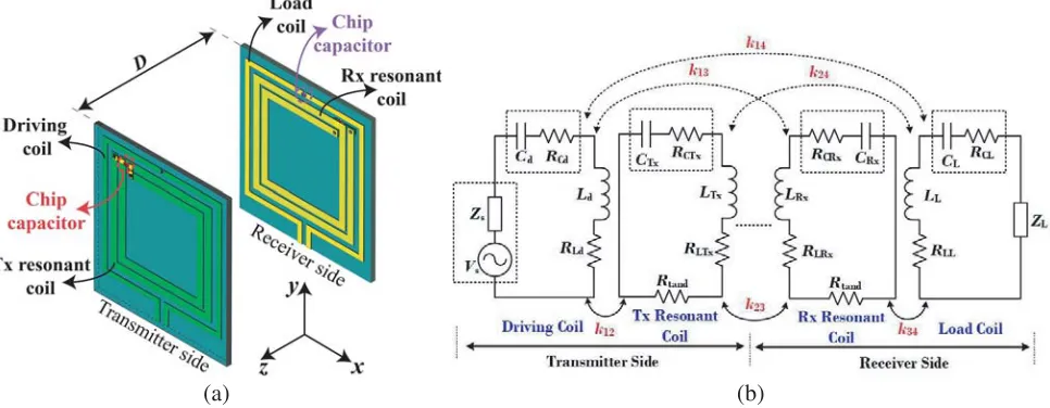
A typical configuration for magnetic resonance-based mid-range WPT systems has four coils, namely (i) a driving coil, (ii) a resonant transmitting coil (Tx), (iii) a similar resonant receiving coil (Rx), and (iv) a load coil as shown in Fig. 1(a). Usually, the WPT performance, commonly measured by the power transfer efficiency (PTE), is referenced to the distance between transmitter and receiver in the order of operating wavelength as well as the dimensions of transmitting and receiving coils [6].
Received 26 September 2019, Accepted 23 November 2019, Scheduled 7 December 2019
* Corresponding author: Sarawuth Chaimool ([email protected]).
1 Electrical Engineering, Faculty of Engineering, Khon Kaen University, Thailand. 2 Electrical and Computer Engineering, King
(a) (b)
Figure 1. (a) Schematic of the investigated configuration of a four-coil system and (b) its considered equivalent circuit.
The quality factor (Q) for each coil and the coupling coefficient k between the coils are two critical parameters for long distance operations with high PTE. However, high-Q does not necessarily imply highk, especially if Tx and Rx coils are not equally sized. The size and geometry of the coils significantly impact Q and k independently. Hence, the modeling of Tx and Rx coils is important to quantifying their performance.
To design coils and enhance the PTE, many techniques have been proposed, such as changing the coil topologies [7–9] and increasing coil sizes [10, 11]. Therefore, different shapes and calculation methods of planar spirals are proposed [12–14]. Due to geometric limitations, increasing Q is one approach to improving the overall PTE when the overall size of the coil is restricted. High-Q resonators are typically made from low-loss conductors and components (low equivalent series resistance), exhibiting low radiation losses. In order to improve Q, moreover, resistance minimization in rectangular and circular spiral coils using track width variations is demonstrated [15]. However, a coil with a larger
Q has a narrower bandwidth. Moreover, in printed circuit board (PCB) manufacturing industry, to ensure solderability and avoid oxidation and corrosion, a PCB surface finish is required. If a surface finish is necessary for a particular RF/microwave circuit design, several issues should be considered because it can impact insertion loss, impedance, and radiation loss. Unfortunately, few papers have been concerned about conducting coated media [16, 17], but they are limited for only wire coils.
In this paper, we consider and analyze power losses in self-resonant coils and external capacitor-loaded (ECL) resonant coils in terms of PTE and transmission coefficient. The contribution of different loss mechanisms is examined. In order to compare the main effect of decreased PTE, we pay more attention to three important parameters: the substrate loss, capacitor resistive loss, and loss from coating materials on copper traces as expressed by the equivalent series resistances (ESRs) as shown in Fig. 1(b). We also construct and utilize our model from a well-established lumped element circuit model [18] to investigate and design a compact WPT system. However, the theoretical calculations of
Q and k are quite complex. Hence, we use the quasi-circuit analysis by using simple approximations of circuit extraction. Our aim is to analyze the factors that cause the power loss and impact on the compact WPT.
2. SYSTEM CONFIGURATION AND ANALYSIS
Rx coils isD. In a conventional four-coil WPT system, both driving and load coils are single loops with or without an external capacitor. In this study, a capacitor is added on the driving coil for adjusting capacitance for impedance matching while the 2TSR coil has been modeled as a series resonant circuit with the external capacitor for the resonant condition. For matching to the 50-Ω system impedance, a chip capacitor, Cd (CL at Rx side), is loaded in the middle of the arm opposite to the feeding point of the driving coil (load coil). A well-established equivalent circuit representation [18] is shown in Fig. 1(b), where each k stands for the respective coupling coefficients, while R represents equivalent series resistances, and L denotes self-inductance of the four coils. Also, C is the capacitance of the external capacitors except in the case of self-resonant coil, which stands for the parasitic capacitance. In order to separately study the distributed losses, we define three main contribution losses by using three ESR groups namely, Rcd, Rcl, RLd, RLL, RLT x, RLRx, RCT x, RCRx, and Rtanδ. The first group of Rcd and Rcl is the capacitor resistive loss in driving and load capacitors while RCT x and RCRx are in the capacitor resistive loss of 2TSR. The second group of RLd, RLl,RLT x, and RLRx is related to strip resistive loss of driving and 2TSR coils, respectively. The last group,Rtanδ, is related to the dielectric
substrate loss. Here, we fix Zs = ZL = 50 Ω. This proposed WPT system is also modeled by taking all mutual coupling coefficients among all four coils; k12, k23, k34, k13, k24, and k14. However, it is often
desirable to simplify the model, and cross coupling coefficients (k13, k24, andk14) can be ignored due to
their very small values.
Although the transmission efficiency and range of WPT systems are limited by the quality factor and coupling coefficient of Tx and Rx coils used, we concentrate on the contribution of power losses in terms of the ESRs which is directly related to the quality factors. Initially, the proposed coils are fabricated on an FR-4 substrate with a dielectric constant of 4.3 and loss tangent of 0.025. The thicknesses of substrate and bare copper are 1.6 mm and 35.6µm (1-oz copper), respectively. The detailed design process of the coils is similar to the resonator in [19]. All the chip capacitors used in this research are from KEMET, thus ESRs in capacitors are from KEMET’s data sheet [20]. The designed resonant frequency of 13.56 MHz is set for both Tx and Rx coils. Here, we define PTE as the ratio of the power dissipated in the 50-Ω load to the available power at the Tx input. The PTE between Tx and Rx coils is calculated and estimated with matched impedance (|S11| ≈0) using the following equation.
P T E= |S21|
2
1− |S11|2 ≈ |
S21|2 (1)
Moreover, the parametric analyses are performed to identify the effects of dominated loss parameters on the transmission efficiency and PTE by using a fullwave electromagnetics simulator CST Microwave Studio [21].
2.1. Self-Resonant Coil and External Loaded Capacitor Coil
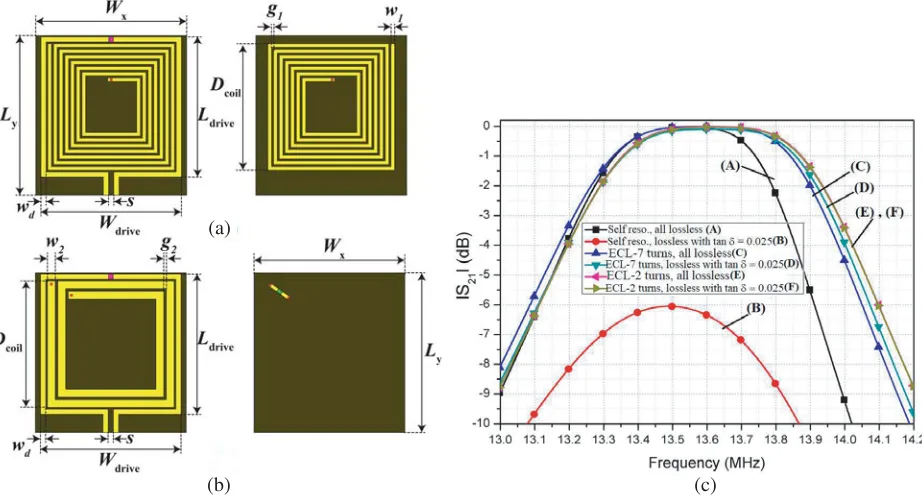
We begin with the design evolution starting from the self-resonant coil and compared to the ECL coil with the same size. There are three cases: (i) self-resonant coil, (ii) two-turn spiral coil, and (iii) seven-turn spiral coil. We design the self-resonant coil using a double-sided seven-turn spiral resonator as shown in Fig. 2(a). For the ECL coils as shown in Fig. 2(b), a lumped chip capacitor is loaded to the coils in series for the resonance at 13.56 MHz. In the current stage, an ideal lossless case is modeled, with all materials losses set to zero, i.e., tanδ = 0 for substrate, PEC (perfect electric conductor) for strip coil, and zero loss in capacitors (ESRs = 0 Ω in case of ECL). In addition, we also compare the lossless case (PEC, ESRs = 0 Ω) with the case of FR-4 substrate with tanδ = 0.025. The detailed dimensions and extracted lumped parameters of all coils are shown in Fig. 2(a), Fig. 2(b), and Table 1, respectively. The comparison of transmission characteristics (|S21|) for the self-resonant coil and the
ECL resonant coils at a distance of 50 mm is shown in Fig. 2(c). It is observed that the magnitude of
|S21|for three lossless cases (A, C, and E) and two cases (D, F) of ECL coils on an FR-4 substrate are
(b) (c)
Figure 2. (a) Geometry of the double-sided seven-turn self-resonant coil. (b) Geometry of the ECL two turns spiral coil when Wx = 58, Ly = 61.5, Ldrive = 54,Wdrive = 54, wd = 2, s= 2, Dcoil = 48.7,
w1 = 1.4, w2 = 3, g1 = 0.79, g2 = 1 (unit: mm.), and (c) comparison of transmission characteristics
(|S21|) of lossless and FR4 substrate cases for self-resonant coil and capacitor-loaded resonant coil at a
distance of 50 mm.
It is also observed in Fig. 2(c) that the transmission bandwidths of all cases are slightly different. Both two-turn coils with lossless (case E) and dielectric loss (case F) have the largest bandwidth of 0.52 MHz. The bandwidth is defined by PTE at 80% or about −1 dB of |S21|. The bandwidths in
descending order are the lossless seven-turn coil, case C (0.514 MHz), the seven-turn coil on FR-4, case D (0.5 MHz), and the lossless self-resonant coil, case A (0.41 MHz). It is well known that the bandwidth is directly related toQof the system. Although all ESRs have zero value for lossless cases, the bandwidth can be considered and calculated using the lossless bandpass filter theory [22, 23]. For this WPT system, the basic mechanism is similar to a two-pole bandpass filter. Fig. 3 shows the calculated transmission coefficient using two-pole bandpass filter technique compared with the simulated result by the CST simulator. In general, the comparison shows good agreement, and the slight difference is due to the extracted parameters being not accurate especially the coupling coefficients. In summary, although the self-resonant coil is more cost effective than external capacitor-loaded coils, Qis largely dependent on the substrate loss, and the resonant frequency is difficult to tune. Based on this characteristic of self-resonant coil, it can be considered as an electrically small antenna with very low radiation efficiency.
2.2. Impact of Substrate Loss
The next parameter to investigate is the substrate loss in terms of dielectric loss tangent (tanδ) of PCB. Basically, the dielectric loss occurs when there is a potential difference between two strips. Therefore, the substrate loss has higher impact on coils with a larger number of turns as shown by the comparison between two and seven turn coils in Fig. 2(c) although the difference is only 0.4 dB. In other words, the dielectric loss can be reduced by decreasing the number of turns. However, when the number of turns is reduced, the magnetic field will also be weakened. Thus, further studies are needed in order to evaluate the effect of substrate loss, especially for the self-resonant double-side coil. A further study for both self-resonant coil and ECL resonant coil is performed by increasing tanδ values and observing the changes in the magnitude of transmission coefficient. Fig. 4(a) shows the change in|S21| as a result of
Figure 3. Comparison of transmission characteristics (|S21|) using the two-pole bandpss filter
technique [22] and simulated by using CST. All extracted parameters are from Table 1.
Table 1. The extracted coil parameters (Fig. 1(b)) of self-resonant coil (Fig. 2(a)) and ECL resonant coil (Fig. 2(b)) for ideal lossless cases when tanδ = 0, PEC strip coil (RLd =RLL=RLT x=RLRx = 0) and no ESRs in capacitors (Rce =Rcl =RCT x=RCRx= 0). Note that all capacitors are added lumped elements except for the case of self-resonant coil.
Cases
Extracted parameters
(units: pF forC and µHfor L) Simulated CST Ref. [24] & [25], [26]
Case I:
Self resonance Double-side 7-turn
Ld=LL= 0.162,
Cd=CL= 330,
CT x=CRx= 21.95,
LT x=LRx= 6.275
Ld=LL= 0.165,
Cd=CL= 330,
CT x=CRx = 22.29,
LT x =LRx= 6.180
Ld=LL= 0.162, Ld=LL= 0.165,
Case II: LT x=LRx= 0.335, LT x=LRx= 0.335, 2-turn coil+C-loaded Cd=CL= 200, Cd=CL= 200,
CT x =CRx= 411 CT x =CRx= 410.48
Ld=LL= 0.162 Ld=LL= 0.165,
Case III: LT x=LRx= 2.277, LT x=LRx= 2.291, 7-turn coil+C-loaded Cd=CL= 240, Cd=CL= 240,
CT x=CRx = 60.5 CT x =CRx= 60.13
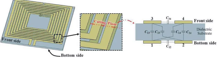
impacts the transmission coefficient. The transmission level decreases from 0 to −12 dB where tanδ is increased from 0 to 0.05, and the PTE is reduced to 6.31% when the PCB has tanδ of 0.05. The reason behind is described as follows. It is well known that the self or parasitic capacitance of a planar spiral coil depends on the relative permittivity of the PCB and configurations of the coil such as the strip width, number of turns, and pitch. As illustrated in Fig. 2(a), parasitic capacitance is introduced by four metal plates as a capacitive coupler, and the circuit model of the four-plate capacitive coupler is depicted in Fig. 5. There are six coupling capacitances, which are created between every two neighboring plates. It is also observed that four capacitances (C13, C23, C14 and C24) are directly coupled through
dielectric substrates. For the sake of simplicity, the substrate loss can be modelled with an equivalent ESR, which is given by ESReqiv= ωCtanδ
eqiv =
1
(a) (b)
Figure 4. Effect of the varying dielectric loss tangent (tanδ) of PCB substrate. (a) Self-resonant coil and (b) external capacitor-loaded resonant coil. Both coils have seven turns.
Figure 5. Parasitic capacitors formed using four-plate capacitive coupler and its circuit model.
For this reason, therefore, the resistive loss of self-resonant double-side coil is considerably affected due to the substrate loss. Thus, as the capacitances come from the gap between the turns and double-sided metal strips, the quality factor of the capacitor is usually very low. As we know, the total quality factor (QT) of the spiral resonant coils is composed of two components, and it is defined as Q1
T =
1
QC +
1
QL
or QT = QQCQL
C+QL, where QL and QC are the quality factors of spiral inductor and spiral capacitor for
self-resonant coil, respectively. Therefore, the totalQT of self-resonant spiral resonator is dominated by
QC of the parasitic capacitor.
In order to increaseQc, therefore, lumped capacitors can be used to decrease the number of coil’s turns. Then, a higher PTE can be achieved as the totalQT is increased. In other words, the capacitor-loaded resonant coil can deliver a larger proportion of the input power from transmitter to receiver in comparison to the self-resonant coil and is less affected by dielectric loss as shown in Fig. 4. In summary, the substrate loss affects the self-resonant coil more than the ECL resonant coil. Therefore, many researchers choose acrylic substrates for implementing WPT systems, because substrate loss does not impact their systems much. However, if the self-resonant coil is needed, low-loss PCBs are required.
2.3. Impact of Capacitor Resistive Loss
capacitors for the ECL resonant coil. Normally, the ESRs in chip capacitors depend on capacitance values and suppliers. The ESR with small capacitance is usually high ESR for the same type of capacitor. For example, the ESR in a 200 pF capacitor is about 0.17 Ω while it is 0.59 Ω for a 60 pF capacitor. This implies that the power efficiency of using a smaller capacitance is lower than using a higher capacitance. Thus, a coil with more turns along with a series matching capacitor is less practical since the required capacitance can be practically too small, and its ESR results in higher loss. In order to clarify the effect of ESR in capacitor, we have designed eight coils with different capacitance values. The ESR values in capacitors are obtained from the chip capacitor’s manufacturers. From the proposed structure, we have two capacitors for each side; one is for matching impedance at the driving loop and the other for tuning resonance at Tx (Rx) coil. In order to compare the effects of ESRs in both capacitors, we study two designs with seven- and two-turn coils. Thus, the capacitance at Tx (Rx) for the two-turn coil is higher than that for the seven-turn coil with the same resonance at 13.56 MHz. It means that the ESR for the two-turn coil is lower. However, the capacitance at the driving coil is opposite. For the case of the seven-turn coil, the capacitance of Tx is 60.5 pF with an ESR of 0.59 Ω, and for the driving coil, the capacitance is 240 pF with an ESR of 0.135 Ω, while for the two-turn coil the capacitance is 411 pF (ESR = 0.07 Ω) and 200 pF (ESR = 0.17 Ω) for Tx and the driving coil, respectively. Fig. 6 shows the|S21|variation with different ESRs in capacitors. It can be seen that two response groups are
observed. The first group has a lower loss of−0.2 dB when either both ESRs of the driving and Tx coils are zero, or the ESRs are zero only at the Tx coil. In contrast, when ESRs at the Tx coil are present, the losses of |S21| are obviously increased by 0.6 dB. The driving coil is the source/load coil, which is
used to couple magnetic field to Tx/Rx coil. Then, magnetic field intensity is mainly generated from Tx/Rx Coil. Therefore, the ESR in capacitor of Tx/Rx coil has more impact on the overall loss than the driving coil. It means that the ESRs in capacitors at the Tx (Rx) coil have impact on the overall losses whereas ESRs in capacitors at the driving coil only have a slight effect as shown in Fig. 6.
Figure 6. |S21| variation with different equivalent series resistances (ESRs) in capacitors of driving
and Tx (Rx) coils.
2.4. Impact of Strip Conductor and Finish Coating Media
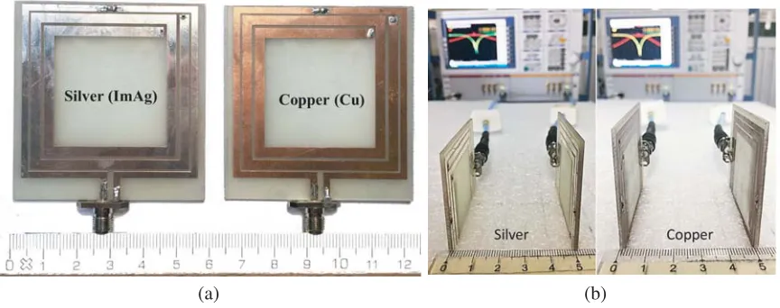
All the above results are conducted with the assumption that all conductors are ideal PEC, while no ideal conductor exists in real applications. In this section, therefore, four types of the conductive media on printed spiral coils used in industrial PCB, including copper (Cu), aluminum (Al), silver (ImAg), and gold (ImAu), are chosen and investigated. Consequently, the surface resistance of coating conducting media on strip coil is not zero, which will cause the loss in system. The general relationships that illustrate the influence ofRs on conductor losses areZs=Rs+jωL,Rs= 1/σδandδ =
2
ωμσ, whereδ
(a) (b)
Figure 7. Effect of different conducting media and the varying thicknesses for the case of capacitor-loaded resonant coil: (a) different conducting media and (b) varying thicknesses.
ESRs) and exhibit low radiation losses. However, since the total coil lengths (33 cm) are much smaller than the wavelength (22 m), the radiation loss is negligible. Accordingly, the conduction power loss could be reduced effectively by increasing the cross-sectional area and reducing the number of turns.
Figure 7(a) shows the comparison of|S21|with five different coating media: PEC, Al, Ag, Au, and
Cu. No noticeable differences in level and bandwidth are observed for the four real coating media (Al, Ag, Au, and Cu). Moreover, they have similar maximum transmission characteristics of−1.6 dB which is lower than the PEC case of−0.6 dB. It means that the coating media do not have obvious effects on both magnitude and bandwidth. In addition, the thickness of the coating layer has also been studied. It is expected that thicker coating media will shift the resonance frequency to higher bands whereas
|S21|changes insignificantly as shown in Fig. 7(b). It may be concluded that the efficiency loss caused
by coating conductors could be ignored in practice.
Moreover, we should further study the characteristics of the whole WPT system with various loss mechanisms for practical applications. Fig. 8 depicts the variation of transmission coefficient with different loss mechanisms for the ECL resonant coil, and Table 2 represents the investigation of the effect of each particular loss. The equivalent circuit parameters, detailed dimensions, and extracted parameters are displayed in Fig. 1, Fig. 2, and Table 1, respectively. It is observed that three line groups are separated. The first group has the highest loss including no. VII and VIII, where all loss parameters are considered. The difference between no. VII and VIII is from the circuit model and EM
Table 2. Comparison for each loss mechanism. The equivalent circuit parameters, detailed dimensions and extracted parameters are displayed in Fig. 1(b), Figs. 2(a), 2(b) and Table 1, respectively.
No. RLd &RLL RLT X &RLRX Rtanδ ESRs in Capacitors |S21|@13.56 MHz
I 0 0 0 No −0.024
II 0 0 0.0026 No −0.04
III 0.501 0 0 No −0.112
IV 0 0 0 Yes −0.592
V 0 0.110 0 No −0.865
VI 0.501 0.110 0 No −0.955
VII 0.501 0.110 0.0026 Yes −1.535
Figure 8. Variations of transmission coefficient versus frequency with different loss mechanisms.
simulator (CST). Both curves achieve 72% (−1.5 dB) efficiency. The second group has medium losses including lines no. IV, V, and VI. In no. IV, only ESRs in capacitors are considered whereas no. V only includes loss in the Tx coil. It is seen that the magnitude of no. V and VI is nearly the same, and no. VI has combined losses in both driving and Tx coils. From this results, again, it can be concluded that the loss in the driving coil is less significant. The last group is the lowest loss (no. I, II and III). Line no. I is the ideal case without any loss. Line no. III has no dielectric, Tx, or capacitor resistive losses and achieves 98% efficiency (−0.11 dB). Line no. II has loss only in the dielectric substrate. Between no. I and VII, we obtain a contrast ratio of −1.5 dB. It is seen that the simulated transmission coefficient is consistent with those predicted by the equivalent circuit model. All results are also tabulated in Table 2.
3. DESIGN VERIFICATION AND RESULTS
To validate our study, several rectangular printed resonant coils with and without loaded capacitors are fabricated and tested. The sizes of all transmitting and receiving coils are identical as 58×61 mm2 on an FR-4 substrate with a thickness of 1.6 mm and loss tangent of tanδ = 0.025. Even though gold (ImAu) shows a possibility of achieving a compact WPT design, the material is quite expensive, and also the simulated results show that it is not significantly different from silver (ImAg). For the PCB with coating media of standard industrial finish, only bare copper and ImAg of 7µm thickness are fabricated.
(a) (b)
(a) (b)
(c)
Figure 10. Comparison of simulated and measured results for copper (Cu) and silver (Ag) conducting coils. (a)|S21|, (b)|S11|and (c) efficiency.
The fabricated prototypes with its measurement setup are shown in Fig. 9 with 50-Ω port impedance. The extracted capacitances are 411 pF and 200 pF for CT x (CRx) and Cd (CL), respectively. These capacitances are also fine tuned in full-wave CST simulations due to the tolerance of chip capacitors. In this case, a 200 pF KEMET chip capacitor is chosen as Cd and CL and 411 pF as CT x and CRx, which result in a Q-factor at 13.56 MHz about 345 and 408, respectively. The chip capacitors are measured with an RLC meter to be 197 pF and 410 pF, respectively. The detailed dimensions are the same as simulations as shown in Fig. 2(b). However, all measurements are restricted for varying only one parameter with others kept unchanged and with all losses included. Several experiments have been conducted to evaluate the transmission coefficient and PTE by measuring the scattering parameters of the Tx and Rx coils as shown by the measurement setup in Fig. 9. The performance of considered coils is measured using a vector network analyzer (VNA) Rohde & Schwarz ZVB20. The measured
S-parameters and PTE are plotted with the results obtained from simulations as shown in Fig. 10 with good agreement. In Fig. 10(a), the simulated results are only 0.33 dB higher than measured ones. The measured|S21|values of both bare copper and ImAg are close to−1.87 dB from 13.3 to 13.8 MHz, which
Table 3. All losses for capacitor-loaded coil at 13.56 MHz. The extracted resistive parameters are RLd = RLL = 0.501 (0.533 Cu), RLT x = RLRx = 0.109 (0.116 Cu) and Rcd = Rcl = 0.17,
RCT x =RCRx= 0.07,Rtanδ= 0.0026 Ω.
Loss Types Magnitude of Loss Copper (Cu) Silver (Ag)
2TSR Coil 0.891 dB 0.840 dB
ESRs in Capacitors 0.568 dB 0.568 dB Drive/load loop 0.094 dB 0.088 dB
tanδ= 0.025 0.020 dB 0.020 dB
Simulation (all losses) 1.573 dB 1.516 dB
Measurement 1.873 dB 1.834 dB
4. CONCLUSION
In this paper, the effects of three dominant loss factors including substrate loss, capacitor resistive loss, and conductive loss on compact magnetic resonant WPT systems are considered and analyzed. From simulated and measured results, it is demonstrated that all three aspects could influence the transmission coefficient and PTE, and cause the decrease in PTE considerably. More specifically, the power loss caused by the dielectric substrate loss can impact the self-resonant coil. Thus, it is recommended that low-loss PCBs are used. On the other hand, the capacitor resistive loss in terms of ESRs and conductive loss contributes to the main losses in loaded resonant coils. To reduce the capacitor resistive loss, a higher capacitance with high-Q is preferred because it usually has a smaller ESR than a small capacitance. Moreover, the transfer efficiency of the whole WPT system with the above three loss factors is 66%. We hope that the presented results could help design highly efficient and compact WPT systems.
ACKNOWLEDGMENT
This work was supported by the young research development project of Khon Kaen University, the Thailand Research Fund under Grant RSA6280056, the Thailand Research Fund through the TRF Senior Research Scholar Program under Grant RTA 6080008, and Chulalongkorn University: CU-GR 61 023 21 002.
REFERENCES
1. Jolani, F., Y. Yu, and Z. Chen, “A planar magnetically coupled resonant wireless power transfer system using printed spiral coils,”IEEE Antennas and Wireless Propagation Letters, Vol. 13, 1648– 1651, 2014.
2. Stein, A. L. F., P. A. Kyaw, and C. R. Sullivan, “High-Q self-resonant structure for wireless power transfer,”IEEE Applied Power Electro. Conf. and Exposition, 3723–3729, Tampa, FL, 2017. 3. Stein, A. L. F., P. A. Kyaw, J. Feldman-Stein, and C. R. Sullivan, “Thin self-resonant structures
with a high-Qfor wireless power transfer,”IEEE Appl. Power Electro. Conf. and Exposition, 1044– 1051, San Antonio, TX, 2018.
4. Li, C. J. and H. Ling, “Investigation of wireless power transfer using planarized, capacitor-loaded coupled loops,”Progress In Electromagnetics Research, Vol. 148, 223–231, 2014.
Raleigh, NC, 2016.
11. Waters, B. H., B. J. Mahoney, G. Lee, and J. R. Smith, “Optimal coil size ratios for wireless power transfer applications,”IEEE Inter. Sym. Circuits Sys., 45–2048, Melbourne, VIC, 2014.
12. Kim, D. H. and Y. J. Park, “Calculation of the inductance and AC resistance of planar rectangular coils,” Electron. Lett., Vol. 52, No. 15, 1321–1323, 2016.
13. Tang, S. C., S. Y. Hui, and H. S. H. Chung, “Characterization of coreless Printed Circuit Board (PCB) transformers,” IEEE Trans. Power Electro., Vol. 15, No. 6, 1275–1282, November 2000. 14. Qian, G., Y. Cheng, G. Chen, and G. Wang, “New AC resistance calculation of printed spiral coils
for wireless power transfer,”Inter. Sym. Quality Electron. Design, 286–289, CA, 2018.
15. Cove, S. R. and M. Ordonez, “Practical inductance calculation for planar magnetics with track-width-ratio,”IEEE Energy Conversion Cong. Exposition, 3733–3737, Denver, CO, 2013.
16. Supriyanto, T., A. Wulandari, T. Firmansyah, and Suhendar, “Design and comparison wireless power transfer base on copper (Cu) and aluminium (Al) rings loop magnetic coupling,” Inter. J. of Infor. Electro. Eng., Vol. 6, No. 2, 110–113, March 2016.
17. Jeong, I. S., B. I. Jung, D. S. You, and H. S. Choi, “Analysis ofS-parameters in magnetic resonance WPT using superconducting coils,” IEEE Trans. Appl. Superconductivity, Vol. 26, No. 3, 1–4, April 2016.
18. Nair, V. V. and J. R. Choi, “An efficiency enhancement technique for a wireless power transmission system based on a multiple coil switching technique,” Energies, Vol. 9, No. 156, 1–15, 2016. 19. Kim, D. H. and Y. J. Park,“Design of a rectangular coil for an effective magnetic resonance wireless
power transfer system,”IEEE Transport. Electrification Conf. Expo. Asia-Pacific, 680–683, Busan, 2016.
20. http://www.kemet.com/capacitors.
21. CST Microwave Studio, Computer Simulation Technology, Framing-ham, MA, 2015.
22. Imura, T., H. Okabe, and Y. Hori, “Basic experimental study on helical antennas of wireless power transfer for electric vehicles by using magnetic resonant couplings,”IEEE Vehi. Power Propulsion Conf., 936–940, Dearborn, MI, 2009.
23. Hunter, I.,Theory and Design of Microwave Filters, The Institution of Engineering and Technology, UK, 2001.
24. Zhao, J., “A new calculation for designing multilayer planar spiral inductors,” Electron. Design, 37–39, July 2010.
25. Mohan, S. S., M. Hershenson, S. P. Boyd, and T. H. Lee,“Simple accurate expressions for planar spiral inductances,”IEEE J. Solid-State Circuits, 1419–24, October 1999.
![Figure 3.Comparison of transmission characteristics (|S21|) using the two-pole bandpss filtertechnique [22] and simulated by using CST](https://thumb-us.123doks.com/thumbv2/123dok_us/1910124.1250363/5.612.131.486.375.595/figure-comparison-transmission-characteristics-using-bandpss-ltertechnique-simulated.webp)