Omnidirectional Conformal Patch Antenna at S-Band
with 3D Printed Technology
Paula P. Sanchez-Dancausa, Jose L. Masa-Campos*, Pablo Sanchez-Olivares, and Eduardo Garcia-Marin
Abstract—A conformal patch array antenna with omnidirectional pattern in the azimuth plane at S-band is presented. A theoretical study of the generated ripple in the omnidirectional radiation pattern according to the number of faces that conform the array has been computed. A six-faced regular prism 3D structure has been chosen following a maximum 3 dB ripple criteria in the omnidirectional radiation pattern. A rectangular microstrip patch fed by a microstrip line has been designed as single radiating element. An equal power divider has been designed as feeding network in microstrip technology to feed each radiating element. Several prototypes have been manufactured and measured to validate the theoretical and simulated results. The entire conformal array has been assembled on a hexagonal regular prism manufactured in PolyLactic Acid (PLA) material using a 3D printer. In spite of the complexity of the proposed antenna structure, the used manufacturing processes, such as microstrip and 3D printing, allows to perform a low cost, low weight and compact final antenna. A higher radiated field ripple than the expected one is generated due to small deviations between experimental and theoretical critical parameters such as the feeding network performance or the 3 dB beam-width of the single element radiation pattern. A maximum ripple value of 4 dB has been experimentally obtained in the omnidirectional radiating pattern.
1. INTRODUCTION
Conformal antennas are designed to take form in several surface shapes either to be integrated in different structures as airplanes [1, 2] or to obtain special angular coverages [3, 4]. Usually, a conformal array antenna is cylindrical [5], conical [6] or spherical [7], and the radiating elements are integrated into the curved surface. Likewise, conformal antennas using printed-circuit technology have been used for several applications in aerospace, or satellite communications due their advantages in terms of low profile, lightweight, low cost or ease of fabrication [8]. Nevertheless, in this kind of antennas the bending of the dielectric substrate can produce a notable efficiency reduction, especially for a large microstrip antenna array [9]. In order to reduce this effect, the curved surface of the conformal array can be approximated by planar faces of an equivalent prism, pyramid or a regular polyhedron [10]. In addition, the difficulty and high cost of the holding structure mechanization can be significantly reduced using 3D printing technology.
On the other hand, one of the possibleE-field patterns to be achieved by these antennas is a 360◦ coverage, either with a narrow beam electronically scanned over the whole azimuth plane or with an omnidirectional beam. This type of conformal arrays has been used in radar or mobile communication systems (base stations). Wider angular coverage and frequency bandwidth, as well as no boresight error due to radome effects have been achieved in comparison to planar arrays [11–13].
Received 24 February 2016, Accepted 18 April 2016, Scheduled 10 May 2016
* Corresponding author: Jose Luis Masa-Campos (joseluis.masa@uam.es).
The proposed antenna consists of a conformal patch array with omnidirectional pattern in the azimuth plane operating at S-band for WiMAX communications [14]. The single radiating element is a rectangular microstrip patch directly fed by a microstrip line ended with a 50 Ω SMA connector. The physical dimensions of the final antenna have been optimized using the conformal array theory to obtain a maximum ripple of 3 dB in the omnidirectional pattern. Therefore, each single radiating element has been positioned on each face of a hexagonal regular prism. In addition, the holding structure has been manufactured in PolyLactic Acid (PLA) material by using a 3D printer, with a significant reduction of both fabrication cost and weight. Finally, a six-way equal power divider as feeding network is designed and manufactured in microstrip technology. The feeding network output ports are connected to the array single elements by means of RG402 coaxial cables.
This conformal array has been designed as a preliminary step of a complex active electronically scanned antenna. An omnidirectional pattern can be achieved using simpler and conventional antennas as monopoles or dipoles. Nevertheless, the proposed design offers a great modularity to easily achieve high gain by accumulating radiating patches in the vertical faces of the prism (maintaining the omnidirectional azimuth pattern), pyramidal arrays with main beam tilt in the elevation plane or enhance the versatility of the antenna by using an electronically switched feeding network to obtain an omnidirectional or sectorial coverage.
In Section 2, the design of the single radiating element and the feeding network, as well as the basic applied theory of the conformal array is described. In Section 3, the experimental results of the whole antenna structure are presented. Finally, the main conclusions and future research are presented in Section 4.
2. CONFORMAL ARRAY STRUCTURE 2.1. Overview
An N-faced regular prism conformal array antenna (Fig. 1) has been set in order to accomplish an omnidirectional pattern in the azimuth plane. Rectangular microstrip patches as single radiating elements have been disposed on each face of the regular prism. A preliminary theoretical design of the conformal array is developed. The distance between the center of the prism and the center of each single element aprism (geometrically this value corresponds to the apothem), the number of prism
faces (N) and the radiated E-field of each single element En(θ, φ) are computed to determine the omnidirectional radiation performance of the final conformal antenna. Finally, an equal power divider as feeding network has been designed in microstrip technology to achieve the required feeding distribution of the final conformal antenna. The final goal of this patch topology in the next future is to enhance the versatility of the conformal antenna using an electronically switched microstrip feeding network. A directive beam instead of the omnidirectional coverage could be then used to aim the antenna in the desired azimuth direction depending on the activated radiating elements.
2.2. Single Radiating Element
A rectangular microstrip patch has been designed and manufactured on a TACONIC RF-35 substrate (εr= 3.5) with 0.762 mm of thickness as single radiating element. A 50 Ω SMA coaxial connector is used to feed the rectangular printed patch through a microstrip line impedance transformer. The dimensions of the rectangular patch are 29.6×22.5 mm while the overall size of the substrate is 52.5×52.5 mm. The width and length of the feeding microstrip line are 1.7 and 26 mm, respectively.
The radiating element has been designed at 3.50 GHz using CST Microwave Studio. The simulated and measured matching coefficient shows a slight shift of the resonance frequency from 3.50 to 3.53 GHz due to the tolerances of the specified dielectric constant by the substrate supplier (Fig. 2(a)).
On the other hand, theH-plane andE-plane normalized radiation pattern is presented in Fig. 2(b). The 3 dB-beamwidth value of the H-plane radiation pattern is 85.6 deg. This parameter has been used to decide the number of faces of the prism for an adequate omnidirectional array radiation and becomes one of the most restrictive parameter in the conformal structure design. TheE-plane response shows an undesirable ripple in the radiation pattern, which is caused by edge effects of the finite ground plane of the single element. Finally, the cross-polarization level is below−15 dB for both main radiation planes.
(a) (b)
Figure 2. Single radiating element. (a) Simulated and measured matching coefficient. (b) Measured normalized radiation pattern.
2.3. Regular Prism Selection
The main difference between the calculated E-field of conformal and planar arrays resides in the single elements orientation (φn), which are not aiming in the same direction in the conformal case. By
including this aspect in the formulation [15], the radiated E-field of the conformal arrayEtot(θ, φ) can be expressed as (1) indicates:
Etot(θ, φ) = ΣNn=1
En(θ, φ)Inej[2λπ·aprism·sinθ·cos(φ−φn)+αn], (1) whereλis the wavelength at the design frequency,N the number of array elements, aprism the apothem
of the prism, andEn(θ, φ),In,αnare respectively the normalized radiatedE-field as well as the feeding current amplitude and phase of then-th single radiating element (N-faced prism scheme in Fig. 1).
Equation (1) has been used as a first theoretical approach to the final radiation pattern in order to obtain the desired omnidirectional behavior in the azimuth plane (θ = 90 deg according to axes in Fig. 1). A regular prism ofN faces has been chosen under the criteria of minimum number of faces that provides a maximum ripple value of 3 dB in the normalized radiation pattern. In this preliminary simple approach, the single element radiatedE-field has been modeled asEn(θ, φ) = cos1.12(φ), emulating the measured H-plane patch beam-width in Fig. 2(b). In addition, an equal amplitude and phase (In=1,
Only even-base prisms have been chosen to compare the different omnidirectional radiation performance of the conformal array. The theoretical results for a four, six, eight and ten faced prism are shown in Fig. 3. In all cases, the length of the side of the prism is minimized by fixing its value to the side of a single radiating element (52.5 mm). Therefore, the number of elementsN can be increased without excessively enlarging the apothem. Thus, a reduction of the radiation pattern ripple can be achieved. The hexagonal prism is the first one to achieve the 3 dB ripple requirement. Therefore, due to simplicity reasons, a six-faced regular prism (N = 6) has been chosen as the shape of the conformal array structure.
Figure 3. Normalized radiation pattern comparison with different number of faces (azimuth plane).
2.4. Microstrip Feeding Network
A six-way equal power divider has been designed and manufactured as feeding network in microstrip technology (Fig. 4(a)). Port 1 represents the feeding network input and the output ports, labeled as 2 to 7, are used to inter-connect the radiating single elements. The same radiating element substrate, TACONIC RF-35 (thickness = 0.762 mm, εr = 3.5, tanδ = 0.002), has been used for the feeding network.
The measured S-parameters are presented in Fig. 4(b). The input matching coefficient (|S11|) is
below −20 dB from 3.3 to 3.7 GHz. The theoretical equal signal distribution performance should be achieved in the mentioned frequency band (|Sj1| ≈ −7.78 dB withj = 2 to 7). Nevertheless, both the
manufactured errors and the substrate dielectric losses, as well as the physical asymmetries of the power divider due to the circuit hexagonal shape, generate degradations in comparison with the amplitude theoretical distribution. A peak difference of ±11 deg is obtained in the phase transmission coefficients
(a) (b)
(phase (Sj1)) of the power divider. The minimum and maximum amplitude values of the transmission
coefficients are −7.77 and−8.26 dB, corresponding to parameters|S41|and|S71|respectively. Finally, the measured feeding network losses are 0.3 dB at the design frequency 3.5 GHz.
3. FINAL INTEGRATION AND EXPERIMENTAL RESULTS
Both the feeding network (microstrip six-way power divider) and the single radiating elements (six rectangular microstrip patches) have been joined to produce the final conformal array antenna (Fig. 5). To achieve an accurate fastening of all the radiating elements, a hexagonal regular prism was built in PolyLactic Acid (PLA) using a 3D printer.
Figure 5. Manufactured conformal array antenna.
The 3D printed structure thickness is 3 mm and includes several drills for the correct assembly of the radiating patches. In addition, four vertical branches holding a platform have been also printed to the right positioning of the feeding network. Likewise, the radiating rectangular patches and the output ports of the feeding network are connected by means of RG402 coaxial cables. All of them have been manually manufactured with the same length in order to keep the phase feeding distribution of the microstrip power divider. The feeding network port 1 (Fig. 4(a)) corresponds to the input port of the complete antenna.
The whole conformal array antenna prototype is shown in Fig. 5. Such as was previously described, the radiating elements and the feeding network as well as the holding structure have been manufactured using microstrip and 3D printing technologies, respectively. Therefore, in spite of the typical mechanization complexity and high price of the conformal antennas, a low cost, low weight and compact antenna has been manufactured.
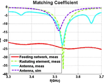
The final prototype has been measured in order to experimentally validate the antenna performance. The measured matching coefficients of the conformal array, the feeding network (Section 2.4) and the radiating single element (Section 2.1), as well as the CST simulation of the entire antenna, are compared in Fig. 6. The measured conformal array matching coefficient is quite similar to the one of the radiating element, keeping the same impedance and bandwidth response. The resonance frequency shift from 3.50 to 3.53 GHz (compared to the antenna simulation) is also observed in the array antenna matching performance due to the tolerances of the substrate dielectric constant, as was described in Section 2.1. Figure 7(a) shows the simulated directivity and the measured realized gain radiation patterns in the azimuth plane (θ= 90 deg) at the measured resonant frequency (3.53 GHz). In addition, the theoretical and the estimated directivities have been also presented. The theoretical calculation uses Equation (1) by approximating theE-field radiation patterns (En(θ, φ)) as sin1.18(θ) and cos1.12(φ) respectively in both
Figure 6. Measured and simulated matching coefficients of the conformal antenna. Measured matching coefficients of the radiating element and the feeding network.
(a) (b)
Figure 7. (a) Radiation pattern in azimuth plane at 3.53 GHz: theoretical directivity, estimated directivity, simulated realized gain and measured realized gain. (b) Normalized radiation pattern in elevation plane at 3.53 GHz.
experimental power distribution (Fig. 4(b)) are used in this case. Sixtyφradiation cutting planes were taken into account in the integration process to obtain the directivity for both theoretical and estimated calculations.
As Fig. 7(a) shows, the maximum points of the simulated and measured realized gain patterns as well as the theoretical directivity are approximately situated in the same angular positions and present similar values. Nevertheless, a slight degradation of the measured pattern due to small deviations in the manufacturing of the feeding network has been detected. As Fig. 4(b) results demonstrate, these manufacturing errors cause an alteration in the feeding phase distribution of the power divider. In addition, slight differences in the length of the six interconnection coaxial cables also affect to the feeding phase performance of the array radiating elements. These effects are confirmed by the estimated directivity curve where the measured single patch radiation pattern and the measured feeding distribution are used to calculate the final pattern. Therefore, a maximum ripple of 4 dB has been obtained in the measured omnidirectional radiation pattern. Likewise, six peak gain values of approximately 2 dBi can be observed, which are almost located in front of each radiating patch of the conformal array.
4. CONCLUSION AND FUTURE RESEARCH
A conformal array antenna at S-band with an omnidirectional pattern in the azimuth plane has been designed, manufactured and measured. The single radiating element consists of a microstrip rectangular patch. A theoretical study of the ripple in the radiation pattern has been carried out depending on the number of faces that conforms the array. Following a maximum 3 dB ripple criteria in the omnidirectional radiation pattern, a hexagonal prism has been chosen as conformal array structure, which has been built in PLA material with a 3D printer. An equal power divider has been designed as feeding network in microstrip technology to feed each one of the single radiating elements. Finally, the whole antenna has been assembled over the 3D printed holding structure connecting both the feeding network and the single elements by means of RG402 coaxial cables. The conformal array antenna has been measured showing maximum ripple of 4 dB in the omnidirectional radiation pattern. This effect is due to the slight deviations in both the manufacturing of the feeding network and the lengths of the interconnection coaxial cables.
Future work in this area includes improvement of the antenna bandwidth using double-stacked rectangular patches as radiating elements. On the other hand, the versatility of the conformal antenna has not been fully analyzed. Using a switched feeding network, the behavior of the antenna in the azimuth plane can be controlled, aiming only in the desired direction instead of an omnidirectional pattern. By enabling only the adequate elements the beam-width of the conformal array can be modified depending on the number of activated radiating elements.
ACKNOWLEDGMENT
This work has been supported by the Spanish Government, Ref. TEC2013-47106-C3-2-R (Project TECOAMP) and Madrid Region Government, Ref. S2013/ICE-3000 (Project SPADERADAR).
REFERENCES
1. Knott, P., C. L¨oker, and S. Algermissen, “Antenna element design for a conformal antenna array demonstrator,” IEEE Aerospace Conference, 1–5, Big Sky, MT, 2011.
2. Steyskal, H., “Pattern synthesis for a conformal wing array,” IEEE Aerospace Conference Proceedings, Vol. 2, 2-819–2-824, 2002.
3. Yang, P., F. Yang, Z.-P. Nie, B. Li, and X. Tang, “Robust adaptive beamformer using interpolation technique for conformal antenna array,”Progress In Electromagnetics Research B, Vol. 23, 215–228, 2010.
4. Athanasopoulos, N. C., N. K. Uzunoglu, and J. D. Kanellopoulos, “Development of a 10 GHz phased array cylindrical antenna system in corporating IF phase processing,”Progress In Electromagnetics Research, Vol. 59, 17–38, 2006.
5. Sahnoun, N., I. Messaoudene, T. A. Denidni, and A. Benghalia, “Integrated flexible UWB/Nb antenna conformed on a cylindrical surface,”Progress In Electromagnetics Research Letters, Vol. 55, 121–128, 2015.
6. Wang, Q. and Q.-Q. He, “An arbitrary conformal array pattern synthesis method that include mutual coupling and platform effects,” Progress In Electromagnetics Research, Vol. 110, 297–311, 2010.
7. Mandri´c, V., S. Rup˘ci´c, and D. Pilski, “Experimental results of spherical arrays of circular waveguide and microstrip antennas,” ELMAR, 2011 Proceedings, 345–351, Zadar, 2011.
8. Shama, A. and S. Dev Gupta, “Design and analysis of rectangular microstrip patch antenna conformal on spherical surface,” 2015 International Conference on Signal Processing and
Communication (ICSC), 366–369, 2015.
10. Huang, M. D. and S. Y. Tan, “An improved spherical antenna array for wideband phase mode processing,” Progress In Electromagnetics Research, Vol. 66, 27–40, 2006.
11. Wang, P., G. Wen, H. Zhang, and Y. Sun, “A wideband conformal end-fire antenna array mounted on a large conducting cylinder,”IEEE Transactions on Antennas and Propagation, Vol. 61, No. 9, 4857–4861, Sept. 2013.
12. Masa, J. L., J. M. Serna, and M. Sierra, “Circularly polarized omnidirectional parch array for millimetre application,”XIX URSI/COST, 284, Sept. 2004.
13. Zhang, Z., X. Gao, W. Chen, Z. Feng, and M. F. Iskander, “Study of conformal switchable antenna system on cylindrical surface for isotropic coverage,” IEEE Transactions on Antennas and Propagation, Vol. 59, No. 3, 776–783, Mar. 2011.
14. IEEE 802.16 Working Group, “IEEE Standard for Local and Metropolitan Area Networks,”IEEE, New York, USA, Dec. 2005.