Energy Management in Multi-Microgrid Sytstems –
Evaluation and Development
Shaik Nadia Yasmin& P.Sarala [Mtech]
1 P. G. Scholar , Department : M.Tech.(E.P.S), 2Associate Professor,Dept Of EEE
1,2 Dr.K.V.Subba Reddy Women's Engineering College, Kurnool, Andhra Pradesh
INTRODUCTION
The structure of conventional distribution frameworks is changed essentially over the previous decades. The presentation of dispersed vitality assets, alongside cutting edge metering, communication and control technologies at the distribution level, has changed the conventional distribution
frameworks into multi-micro grid
frameworks which are typically quicker,
increasingly controllable and solid.
Conceivably, there are a few sorts of vitality assets and vitality customers in multi-micro grid frameworks. The nearness of vitality assets, (from fixed and dispatchable capacity to probabilistic and discontinuous nature DGs), and vitality purchasers, (from fixed and non-controllable to hourly and probabilistic variable burdens), in the framework, have showed the requirement for ideal administration of vitality in multi-micro grid frameworks.
Vitality the executives in present day
distribution frameworks has been a
fascinating exploration region for as long as decades. A few undertakings have been distributed on various vitality the executives choices in brilliant grids, from ideal planning of vitality assets to request side vitality the executives. With the expanding limit and assortment of them, electric stockpiling units have been an engaging subject for performing vitality the board. In addition, the quantity of electric vehicles is expanding in distribution frameworks, which likewise raised a few research openings, particularly as far as vitality the board.
A few specialists have additionally been distributed in vitality the board on micro grid] with multi-operator or potentially multi-level control structures. For instance, the creators in proposed a two-level engineering for dispersed vitality asset the board for multiple micro grid utilizing multi-operator frameworks. A symmetrical task issue dependent on innocent sale calculation is utilized in their undertaking so as to coordinate the purchasers and dealers in the vitality advertise.
Keywords: Microgrid, Energy, Electrical, Storage.
1.2 LITERATURE SURVEY
In the literature survey of “ENERGY MANAGEMENT IN MULTI MICRO GRID SYSTEM – EVALUATION AND DEVELOPMENT”
IN 2015 W. TUSHAR; B. CHAI; C. YUEN;"Optimal Energy Scheduling for Residential Smart Grid with Centralized Renewable Energy Source" the sustainable power source offers a less expensive and cleaner vitality supply, it acquaints supply vulnerability due with the instability of inexhaustible source. It is along these lines of useful significance to research the ideal misuse of sustainable power source dependent on the supply-request structure of future brilliant grids, where the vitality suppliers (or the vitality clients) adaptively alter their vitality provisioning (or vitality requests) as indicated by some framework state data that considers the unpredictability of inexhaustible energy.[6]
In 2015 Y.S.FO EDDY, H.B. GOOI,
"MULTI AGENT SYSTEM FOR
MICRO GRID" Solar and wind vitality are the main answers for the developing vitality emergency on the planet. The discontinuous idea of the sustainable power source impacts the elements and strength of the micro grid. Keeping up a dependable and stable grid will necessitate that these elements be adjusted continuously. The current grid is insufficient to adapt to the high entrance of discontinuous sustainable power source and complex control choices because of the absence of adaptability and extensibility. Reconciliation of sustainable power source on to the electrical grid requires dynamic vitality the executives abilities due to its irregularity. The significance of having progressively solid, effective, shrewd frameworks is getting more mindfulness and open consideration. Developing technologies help enhance productivity and lessen natural effects of vitality generation and consumption.[7]
In 2015 W.Tushar,B.chai, "Three-Party
Energy Management With
DistributedEnergy Resources in Smart Grid" the advantages of dispersed energyresources (DERs) are considered in a vitality managementscheme for a savvy network comprising of a vast numberof private units (RUs) and a common office
controller (SFC).A non-agreeable
Stackelberg amusement among RUs and the SFCis proposed so as to investigate how the two elements can profit, interms of accomplished utility and limiting all out expense respectively,from their vitality exchanging with one another and the grid.[8]
In 2017 SEYED ALI AREFIFAR,
"Arranging AND OPERATION OF
SMART GRIDS", This undertaking speaks to that the keen grid's intricacy will develop after some time require new technologies for effective, dependable and secure activity and control as the interest for power
increments. Enhancement for frameworks effectiveness and the utilization of inexhaustible sources are a few points to take a shot at to lessen anthropogenic ozone harming substance outflows, due that micro grid, loads demonstrating power quality".
Such appraisal incorporates into
advancement of intensity quality and assessment of micro grid system.[10]
THEORETICAL ORIENTATION 2.1 THE CONCEPT OF MICRO GRID Many research groups far and wide are spearheading different microgrid ideas, likewise composed as micro grids, as an elective methodology for coordinating little scale distributed vitality assets (DER of < approx. 1 MW) into low-voltage power frameworks. Numerous different terms are in like manner use to depict comparable ideas, for example virtual power plants, minigrids, keen grids, savvy distribution networks, embedded generation, distributed or dispersed generation.
Customary ways to deal with inserting generation at low-voltages center around limiting the ramifications for security and grid execution of what are thought to be a
moderately modest number of
independently interconnected DER, for instance suggesting, that they should quickly disengage in case of framework blackout. At the end of the day, allowed neighbourhood control of gadgets is exceptionally restricted, and they can work autonomously, or islanded, just under uncommon conditions, for example amid power outages after the nearby framework is completely detached from the large scale grid. Paradoxically, µGrids would be intended to work semi-freely, generally working associated with the full scale grid yet isolating (islanding) from it, as practical
or fundamental for dependability or
A Micro grid is a semiautonomous grouping of creating sources and end-use sinks that are set and worked to assist its individuals, which might be one utility "client," a grouping of a few locales, or dispersed destinations that in any case work in a planned style. The supply sources may incorporate responding motor generator sets, micro turbines, power devices,
photovoltaic and other little scale
sustainable generators, stockpiling gadgets, and controllable end-use loads. Every single
controlled source and sinks are
interconnected in a way that empowers gadgets to play out the µGrid control capacities pointless for conventional DER. For instance, the vitality equalization of the framework must be kept up by dispatch, and non-basic burdens may be shortened or shed amid times of vitality shortage or mind-boggling expenses. While equipped for working autonomously of the full scale grid, the µGrid for the most part works interconnected, buying vitality and auxiliary administrations from the large scale grid as monetary, and conceivably moving back now and again.
Three key potential highlights of the µGrid are:
1. its plan around all out framework vitality necessities
2. its arrangement of heterogeneous
dimension of intensity quality and dependability to end-employments 3. its introduction to the large scale grid as
a solitary controlled element
2.1.1 Design around Total System Energy Requirements
It infers that to the degree financial or wanted for natural purposes, the µGrid shares warmth and control and ideal
recuperation of waste warmth by
consolidated warmth and power (CHP) gadgets. While little scale warm generation of power is probably not going to be
focused with focal station generation, the drastically enhanced prospects for helpful waste warmth recuperation, particularly in assimilation cooling frameworks, can tip the monetary scales towards DER. The course of action of µGrids develops from the need
to streamline the general vitality
arrangement of the endues, and since transportation of warmth is ordinarily more restricting than transportation of power, the area of warmth loads is probably going to rule.
2.1.2 Provision of Heterogeneous Level of Power Quality and Reliability
It recommends a focal objective of µGrids concerns fitting PQR to the necessities of endues, an obviously unexpected guideline in comparison to the arrangement of all inclusive reliable administration quality, which is the objective of micro grids. The µGrid is fabricated and worked so basic burdens are secured and high-control quality is guaranteed where it is vital, while different burdens are presented with PQR
similar with their significance and
additionally reschedulable. The arrangement
of heterogeneous PQR can enhance
generally speaking unwavering quality of basic gear while bringing down expenses due to the penance of non-basic ones.
2.1.3Presentation to the Micro grid As a Single Controlled Entity
It concerns the µGrid's introduction to the encompassing distribution grid as a solitary controlled framework, much the same as a present client, or alternately to a little embedded generation source. The µGrid engineering guarantees that its electrical effect on the distribution grid isn't just as a decent subject that does no damage yet in addition conceivably as a model native, adding advantages to the distribution
framework, for example, lessening
voltage backing, and reacting to fast changes in burden levels. Regardless, the key normal for a µGrid is the presence of nearby control free of the large scale grid. This control could be executed by different technologies and be of variable multifaceted nature, however its reality characterizes the µGrid.
2.2 ENERGY MANAGEMENT IN A MICRO GRID WITH DISTRIBUTED
ENERGY MANAGEMENT
A brilliant grid control framework with sustainable power source assets and distributed energy storage indicates critical enhancement in the power framework's
emanation decrease, dependability,
productivity, and security. A micro grid is a shrewd grid in a little scale which can be remain solitary or grid-tied. Multi micro grids structure a system with energy the
executives and operational arranging
through two-way control stream and communication. To thoroughly assess the execution of a micro grid, an execution metric is proposed with thought of the power value, outflow, and administration quality, every one of them is given a weighting factor. In this way, the execution metric is adaptable as per the purchasers' inclination. With the weighting factors set in this execution metric is additionally connected on micro grids worked as remain solitary, grid-tied, and arranged. Each micro grid comprises of a sun powered board, a hydrogen energy component stack, an electrolyze, a hydrogen storage tank, and a heap. For an independent framework, the heap expectation lets down the day by day power utilization about 5.7%, and generally execution lists increment with the sun oriented board estimate. In a grid-tied MG, the heap forecast significantly affects the day by day expended power which drops 25% in 4 days, sometime in the not so distant future time loads are moved to the
evening time, and the limit of hydrogen tank is lower than that in an independent MG.
2.3 OPTIMUM MICRO GRID DESIGN FOR ENHANCING RELIABILITY
Micro grids are known as bunches of distributed energy assets serving a group of distributed loads in grid-associated and secluded grid modes. These days, the idea of micro grids has turned into a key subject in the shrewd grid zone, requesting a deliberate methodology for their ideal development. As indicated by the huge distribution frameworks can be bunched into various micro grids to encourage amazing control and activity infrastructure in future distribution frameworks. In any case, grouping substantial frameworks into a lot of micro grids with high dependability and security isn't accounted for in current writing. To round out this hole, shows a precise and upgraded methodology for
planning micro grids considering
framework unwavering quality and supply-security-related aspects. It is seen that, by expanding the quantity of hours that have 10% forecast blunders for burden and generation, the determined mistake for EMSI and day by day costs will increment. Besides, the blunder in determined EMSI and day by day costs is somewhat bigger if the mistake is in the measure of intensity anticipated to be created by the DGs.
The ideal plan thinks about continued and transitory shortcomings, for framework unwavering quality through a consolidated probabilistic dependability record, and genuine and responsive power balance, for supply security. The heaps are thought to be variable and diverse distributed generation
(DG) technologies are considered.
framework. The impact of optimization coefficients on the structure and the strength of the calculation are examined utilizing affectability ponders.
2.4 DEMAND-SIDE MANAGEMENT
VIA DISTRIBUTED ENERGY
GENERATION AND STORAGE
OPTIMIZATION
Distributed generation technologies have risen against terrible condition and energy emergency, and they have been created well as of late. Bunches of individuals have given careful consideration to keen grid at home and abroad. The essential job of the
distributed power generation in the
advanced system's security and unwavering quality, especially the application and improvement of distributed generation (DG)
in the shrewd grid. Request Side
Management (DSM) must adjust the
inconsistencies between the supply
framework and utilization, as a developing force generation industry, the fundamental element is that they are near the clients and can work autonomously or grid-associated.
Request side administration, together with the reconciliation of distributed energy generation and storage, are viewed as progressively fundamental components for executing the keen grid idea and adjusting enormous energy creation from sustainable sources. A savvy grid in which the interest side involves conventional clients just as clients owning some sort of distributed energy sources as well as energy storage gadgets. By methods for multi day-ahead optimization process managed by a free focal unit, the last clients expect to lessen their money related energy cost by delivering or putting away energy instead of simply buying their energy needs from the grid. In this, we detail the subsequent grid optimization issue as a noncooperative
diversion and investigate the presence of ideal techniques. Moreover, we present a distributed calculation to be kept running on the clients' shrewd meters, which gives the ideal creation and additionally storage systems, while protecting the security of the clients and limiting the required motioning with the focal unit. At last, the proposed day-ahead optimization is tried in a practical circumstance.
Optimization of Energy Systems completely portrays the thermodynamic displaying, examination and optimization of various kinds of energy frameworks in different
applications. It gives another
comprehension of the framework and the way toward characterizing appropriate target capacities for assurance of the most
reasonable structure parameters for
accomplishing upgraded productivity, cost viability and manageability.
Storage optimization is the aggregate procedure, systems and technologies that empower the proficient utilization of storage infrastructure and assets. It is a wide idea that works over all the innovative and the board layers of storage the board to guarantee existing storage assets are working in a proficient and financially savvy way.
Storage optimization fundamentally limits the disk/storage use over all storage levels and assets. Ordinarily, the objectives of storage optimization are to decrease storage equipment and organization costs, solidify existing storage assets through server
virtualization, and this guide to
based storage mechanization are a portion of the procedures and technologies utilized in storage optimization.
THE CONCEPT OF ENERGY
MANAGEMENT AND ITS ELEMENTS
FIG. 3.1. PROPOSED VERSUS EXISTING ENERGY MANAGEMENT SCENARIOS
3.1 THE ANAYLIS
The results of several interesting research projects have been published in the energy management area], the literature does not report the development of a systematic approach for combining and comparing a variety of energy management options in a multi-micro grid system, where each micro grid, simultaneously, has different types of DGs, storage units, EVs and demand responses. Moreover, the issue of assessing different energy management scenarios in distribution systems in order to provide insights that will contribute to the success of different available energy management programs is not resolved yet. Given the importance of energy management in smart grids, this project formulates a day-ahead planning strategy for performing optimized and coordinated energy management in multi-micro grid systems. As shown in Fig.3.1.1, such planning will simultaneously supervise several energy resources and energy consumers in multi-micro grid systems that include dispatchable and non-dispatchable intermittent nature DGs, energy storage units, large numbers of electric vehicles and demand response. With this plan, all the controllable generation/consumption
devices in different micro grids are controlled by a central energy management system and operate in accordance with each other (either in the same or in different micro grids) to minimize operational costs. Due to the presence of probabilistic nature DGs and loads in the system, to calculate the total operational costs and show how an energy management scenario will affect operational costs, a new probabilistic index is defined to measure the success of energy management process. A case study is also presented to compare and decide between different options for performing energy management in a multi-micro grid system. Energy management is then performed for different energy generation/consumption units individually and collectively.
3.2 THE CONCEPTS AND SYSTEM COMPONENTS
Thus, implementing certain measures to manage the generation/consumption devices can enormously reduce the costs for reaching the balance. In this project, the load-generation balance in a multi-micro grid system is achieved with the objective of minimizing the utility costs, the load and generation uncertainties in the micro grids are predicted for the next 24 hours and by considering the hourly price of electricity, the optimum state and amount of power generation/consumption by the controllable devices are determined. Regardless of which energy management approach is selected for a multi-micro grid system, the process can be performed hourly or in shorter periods, e.g., every 10 minutes, in order to achieve more accurate and continuous results. Moreover, if the predicted data is not available for 24 hours, the same approach can be implemented for a shorter period of time as well (e.g. 10 hours). The following subsections explain
the models of typical energy
generation/consumption units in a multi-micro grid system and how they can be managed in order to reduce the utility costs.
3.2.1 DISTRIBUTED GENERATION UNITS
The DG units are essential components in micro grids and are modeled in this project as a combination of PV modules, wind turbines and biomass generators, which are the typical components of the most commonly, used DGs in distribution systems.
3.3 PROBLEM FORMULATION
The probabilistic representation of load-generation states and the steps for
formulating the proposed energy
management success index are presented in this section.
3.2.1PROBABILISTIC
REPRESENTATION OF LOAD-GENERATION STATES
The DG types presented in this project have probabilistic, intermittent probabilistic and
constant power natures, which
mathematically covers the models used for all types of DGs. Therefore, any other type of DG, such as CHP, etc. can be modeled using a similar approach. The output of each PV Module depends on the amount of solar irradiance, the ambient temperature and the characteristics of the module itself. The output power of wind turbines depends on the wind speed and the parameters of the turbine’s wind-power conversion curve. Detailed approaches for modeling such DGs are explained. The biomass generators provide stable firm generation with constant but controllable output powers, and are not affected by uncertainty.
In case of uncertainty in the factors that affect the availability of biomass, such as rain, the biomass DGs’ output powers can be modeled in a similar way to those of wind turbine generators. For the purposes of energy management, the wind turbine and PV modules output powers are predicted for the next 24 hours by using the short-term forecast data for weather conditions. Using such data and the price of electricity for the next 24 hours, the optimum output power of the biomass DGs is predicted hourly for up to the next 24 hours.
3.2.2 ENERGY STORAGE UNITS
discharging time periods. The optimal schedule for the operation of the storage units will be determined in this research based on the cost of energy, the cost of operating storage units, etc., for the next 24 hours. A constraint has been introduced on the amount of power generated by the storage units, which should be less than total loads at any time. This constraint ensures that, even during off-peak hours, the real power of storage units is less than total demand and guarantees that the reverse power flow, if any, can be modified by controlling the DGs’ output power only.
3.2.3 ELECTRIC VEHICLES
Electric vehicles (EVs) add enormous uncertainty to the analysis of micro grid systems. EVs can be considered as loads
during charging periods or as
loads/generators if they are participating in V2G programs. From a different point of view, EVs can be charged at home in residential areas or be connected to aggregate EV charging stations. As shown in, during charging periods, the EVs can be modeled as probabilistic loads with a Normal distribution function in residential communities, while in EV aggregate charging stations they can be modeled probabilistically using the Weibull distribution function. In this research, all four scenarios are considered, which are
EVs being charged in residential areas, modeled as probabilistic loads with Normal distribution,
EVs being charged in aggregate EV stations, modeled as probabilistic loads with Waybill distribution,
EVs being discharged through V2G program in residential areas, modeled as probabilistic generators with Normal distribution,
EVs being discharged in V2G program in aggregate EV stations, modeled as probabilistic generators with Waybill distribution.
TABLE.3.1 SELECTING
NUMBER OF STATES FOR
PROBABILISTIC STUDY
3.2.4 LOADS
The first two scenarios are modeled as controllable loads for which we can determine the time of charging based on a specified time period, e.g., night hours. The last two scenarios are considered as controllable loads/generators for which we can determine the timeframe and amount of their consumption/generation depending on the selected energy management strategy. In order to determine the probability density functions of EVs, the probability distribution parameters (normal or Waybill) of the EVs can be assumed to be constant or, similarly to the peak EV load pattern, can be predicted by using the historical data. The loads in micro grids are modeled considering in this system, the hourly peak load is presented as a percentage of the daily peak load. In order to gain more accurate energy management results, the prediction techniques could also be used for modeling the loads probabilistically or hourly. Some of the loads are assumed to be controllable and available for demand side management purposes. Such loads are considered as transferable from time to time, e.g., from on-peak to off-peak hours.
3.3 PROBLEM FORMULATION
The probabilistic representation of load-generation states and the steps for
formulating the proposed energy
management success index are presented in this section.
3.3.1 PROBABILISTIC REPRESENTATION OF LOAD-GENERATION STATES
continuous probability density function of the output power of the wind turbines and PV modules, and the EVs charge/discharge pattern for each hour of the day, is divided into a number of states. The selected number of states affects the accuracy and complexity of the formulation. Selecting a small number expedites the calculation process but lowers the quality of results, while selecting a large number increases the quality of results at the expense of calculation time Therefore, for each hour of the day we select 12 wind-speed states (NW), 12 solar-irradiance states (NS), and 12 EV charge/discharge states (NEV). In this research, the wind speed and solar irradiance and the Eves’ behavior are modeled independently for each hour based on their historical distribution; therefore, the inter-temporal or any other correlations are not considered. Assuming that solar irradiance, wind speed and the Eves’ charge/discharge states are independent, the probability of any combination of load and generation is obtained by multiplying all the probabilities.
Each load-generation state has its own probability of occurrence. If the inter-temporal correlations of wind speed and solar irradiance are to be considered, the probability of each state cannot be calculated by simply multiplying the probability of each state of wind speed and solar irradiance. In fact, the only difference between considering or not considering the correlations will be in the method of calculating the probability of each load- generation state. In the former scenario, the probability of each generation state should be calculated by convolving the two probabilities of wind speed and solar irradiance; however, in the latter scenario, the probability of each state can be calculated by simply multiplying the two probabilities. This may slightly affect the
computational tractability in terms of the calculation of probabilities; however, since the formulations of the problem and solution algorithms will remain the same, the proposed method is still practical and useful in high-renewable systems.
3.3.2 ENERGY MANAGEMENT OBJECTIVE FUNCTION
The aim of performing energy management in a multi- micro grid system is mainly to reduce operational costs. This section explains the calculation of total operational costs and introduces an index to show how an energy management scenario affects operational costs in a micro grid full of probabilistic parameters. The overall costs or EMSI is then calculated by deterministically calculating the costs or EMSI for each load-generation state and its accumulation considering the probability of the states.
The steps to calculate the operational costs and the EMSI for the simultaneous consideration of all energy management options, as well as for the individual consideration of each energy management scenario, are explained in the following. It should be noted that, since the purpose of this project is to assess different energy management scenarios, only the costs that will be affected by energy management process (operational costs) are investigated, and other costs, such as planning costs, are not considered in this research.
(PDG) to a number of loads instead of purchasing power from the upstream system (third part of (3)). The upstream system is part of the system that supplies each micro grid. It could be the grid itself, if the micro grid is directly connected to the distribution substation, or it could be another micro grid that connects the specified micro grid to the network
where Plush is the total system losses at time h; Czech is the cost of energy at time h; PDG_kh is the output power of kth DG at time h; CDG is the cost of generation for the biomass DGs and NDG is the number of dispatchable DGs in the system. In this project, the dispatchable DGs are set as biomass-based and the cost of generation is assumed to be the same for all generators. The electricity generated by such DGs is usually costlier than that generated by large power plants; therefore, CDG could be larger than Czech.
It is assumed that, before energy management, the DGs are working at nominal power and, after that, the output powers of DGs are determined through an optimization process. The total operational benefits/costs of storage units (TCESS_j) at jth load-generation state, before and after energy management, can be calculated from, which is different for the charge and discharge period of the storage units.
Czech is the cost of energy at time h, PESS_kh is the real power (charge or discharge) of kth storage unit at time h, CESS is the cost of charge/discharge for the storage units, ηESS is the efficiency of the storage units and NESS is the number of storage units in the system. It is assumed
that, before energy management, the storage units are not in service and, after energy management, the charge/discharge amounts and periods are determined by the optimization process.
The total operational benefits/costs of performing demand side management (TCDSM_j) at jth load-generation state, that will be affected, arise from energy losses, which cost different amounts at different hours and are calculated.
where Plush is the total system losses at time h; and Czech is the cost of energy at time h. In a long-term vision, the demand side management may postpone some system upgrades that should be performed by the utility and will reduce the utility costs.
The electric vehicles, whether charged through EV aggregate or residential buses, can be treated as controllable loads and storage units simultaneously. However, there are some restrictions that should be considered. Firstly, the behavior of EVs is not deterministic; the charging and discharging scenarios, as well as whether the EVs are parked or on the road, is probabilistic. For this research, it is assumed that 50% of EVs are participating in the V2G program, which means that they can also be considered as generators as long as they are not being charged, and the probability that the car is parked in EV stations or at houses follows the probabilistic model presented in therefore, as was done with the formulations regarding storage units, the total operational benefits/costs of the utility that are related to the operation of EVs (TCEV_j) at jth load-generation state, can be calculated. The only difference between EVs operating as storage units and the storage units is that the cost of charging the EVs will be paid by the vehicle owners and not by the utility; therefore, the total cost will equal zero at charging periods and the period of charging for the EVs will only affect the system losses which cost different amounts at different hours.
Also, it is assumed that if the vehicles are participating in V2G program, the utility is already compensating their participation during discharge periods; however, the compensation can also be considered separately for taking control over charging periods, and can be added as a cost for the utility du ring this period as well.
where Plush is the total system losses at time h; Czech is the cost of energy at time
h; PEV_kh is the discharged power of kth EV bus; Cobh is the cost of buying electricity from EV owners at time h; dev. is the percentage of EVs participating in the V2G program, and NEV is the number of EV buses in the system. After calculating total operational costs for all the devices including DGs, ESSs, DSM and EVs, the utility’s total operational costs for each load-generation state can be formulated as:
The EMSI can then be calculated by using above equation and by calculating the costs before and after performing energy management.
3.4SOLUTION ALGORITHM
best solutions previously found using other
approaches. There are also some
disadvantages, e.g. many parameters must be determined to reach the global optimum and the number of iterations could be large.
Considering the advantages and
disadvantages of TS and the nature of the formulated problem, TS will be an appropriate and efficient solution algorithm. The steps needed to solve the optimization problem using the TS algorithm are shown in Fig. 3.4.1 and explained in the following sub-sections.
TABLE 3.4 SELECTION OF NUMBER OF ITERATIONS
3.4.1 NEIGHBOURHOOD DEFINITION IN TS
The first step in TS is to select the starting point, and the process continues iteratively until a certain criterion, which is usually the maximum iteration numbers, is reached. Selecting a small number as the maximum number of iterations will affect the final results. However, if the maximum number of iterations is selected properly, the whole search space will be covered and examined. The maximum iteration number depends on the nature of the problem and decision variables. One approach to setting the maximum iteration number is to increase it continuously until there is no improvement in the objective function value, as was done in the research described in the. Table II shows the effect of selecting different maximum number of iterations on the objective function for a simple optimization problem with the objective of optimizing EMSI (Section V-C). It is seen that, by increasing the number of iterations, the objective function will improve up to a certain value.
The starting point can be selected as a decision variable with arbitrary but feasible values. For example, the values of PDG, PST, PDM, and PEV could be all set as zero or 0.5 pp. to start the process. The interesting fact about the Taboo search is that the final solution is not dependent on the starting point at all and, by using long-term memory, the search process jumps into new regions whenever no improvements is seen in a specific region. Therefore, it will be possible to select any value as the starting point without leading to different solutions. The decision variables for performing energy management by using the kth system component for the next 24 hours can be shown as the following vectorswhere the components of PDG_k, PST_k, LDM_k and PEV_k represent the output power of DGs, output/input power of storage units, load percentage to be supplied and charge/discharge power of EVs for the next 24-hour time period, respectively. The next step is to make sets of neighbors for all the starting points. Each neighbor is selected by changing a number of components of each vector and checking its feasibility in terms of the constraints which are voltage and current limits and DGs capacities. This number is chosen based on the size of the decision variable vectors. A small number will make the neighborhood more homogeneous and a large number makes it more diverse.
changing three components to make a new neighbor is appropriate. Selecting the maximum number of neighbors will affect the final results. The effect of selecting a different number of neighbors on the objective functions for the same case study. It is seen that, by increasing the number of neighbors, the objective function will improve up to a certain value.
F.I.G.3.4.1 THE FLOW CHART OF ENERGY MANAGEMENT
Next, the best neighbor is set as the new starting point and the process continues until the maximum number of iterations is reached. Different memory structures, such as short-term (Taboo list), intermediate-term and long-term memories, are implemented to diversify and intensify the search process and reach the global optimum more effectively.
3.4.2 TABOO LIST AND ASPIRATION
To avoid stopping in a local optimum, and to prevent cycling around it, some Taboo restrictions should be imposed by using a short-term memory called Taboo List (TL). This list, which has a FIFO (first in first out) structure, keeps track of the best solutions that have been visited in previous moves, or the moves that have resulted in the optimum point in previous regions, and
avoids revisiting them. The length of TL depends on the size of the problem and is usually determined experimentally. In our problem, we have made the TL from the best recently visited solutions. For this purpose, a quantity, which is unique for each set of parameters, is saved in the TL as shown in:
It shows the effect of selecting different TL values on the objective function for a simple optimization problem with the objective of optimizing EMSI. It is seen that, by increasing the TL, the objective function will improve up to a certain value and then will worsen. The reason again is that selecting a large number as TL will prevent the search from concentrating in a specific region to find the local optimum (potentially global optimum). An aspiration criterion is a rule that releases the valuable members of Taboo list. This relaxation is allowed when the newly met solution point has better properties than the optimum point reached so far. This phenomenon will make the search process more intelligent and prevent it from missing higher quality results.
3.4.3 INTENSIFICATION AND DIVERSIFICATION IN TS
By focusing on demand-side load management applied to the residential sector. A home automation system controlling household energy is proposed. It is decomposed into three layers: anticipation, reactive and device layers. This paper deals with an anticipation layer that allocates energy by taking into account predicted events. It consists in computing both the starting times of some services and in determining set points of others while satisfying the maximal power constraint. A constraint satisfaction problem formulation has been proposed. Because the complexity is NP-hard, a Tabu search is used to solve the problem. It maximizes user comfort and minimizes energy cost.
Two memory structures are used in TS to avoid random search, namely, Intermediate-Term Memory (ITM) and Long-Intermediate-Term Memory (LTM). The ITM memorizes the common features of sub-optimal solutions for a number of iterations and then tries to search for the optimum point with similar features in that region. This intensification process will guide the search in each region to identify the high-quality solutions rather
than to make random undirected
movements. During the search process, the LTM is used to diversify the search by jumping to a new region and allows the algorithm to go through all the possible solutions to find the global optima. If the maximum number of iterations is selected properly, the whole search space will be covered and examined.
The two types of memories have been implemented for each decision vector by using two sets of vectors with the same length as the decision variables. Each component of the ITM vectors will represent the number of times the associated component has been changed in the sub-optimal solutions. Thus, the next movements or neighborhoods will be selected so that the components that are thought less likely to be the optimum have a
higher chance of being changed. The long-term memory is also implemented in a similar way. As a sub-program, the forward-backward power flow algorithm is also a well-known method used for power flow calculations in radial distribution systems.
During the optimization process, the AC forward-backward power flow is run for each load-generation state and the results, such as energy losses or EMSI, are accumulated by considering the probability of the states. It should be noted that in this project, it is assumed that the distribution system is radial; therefore, the best option for performing power-flow would be the
forward-backward method. However,
selecting a different power flow method will not affect the proposed energy management scheme.
F.I.G.3.4.2MULTIMICRO GRID
SYSTEM AND LOCATION OF
COMPONENTS
of the system, the micro grids are connected together and to the grid. Therefore, the grid power is also covering part of the energy required by the loads inside the micro grids. However, the same formulations and approach can be used in cases where the micro grids are operating in islanded or off-grid mode. The reactive sources are modeled as fixed generation installed on specific buses. The reactive sources could be fixed capacitors (e.g. bus 5) and their location and capacity are predetermined based on the construction of the micro grid. In cases where there are variable reactive sources, they may also be used for voltage/line loading control. In such cases, the generation capacities of reactive sources can be considered as decision variables for optimization problems, in a similar approach to that taken with active power
ASSESSMENT OF ENERGY MANAGEMENT OPTIONS
The system under study and the energy management approaches proposed for a multi-micro grid system are presented in this section.
MULTI-MICRO GRID ISOLATED ENERGY MANAGEMENT
At this stage, the holistic energy
management process covering all
generation/consumption devices is
implemented for each micro grid separately, and the results are presented. The
operational costs for each
generation/consumption unit are explained in details in Section VI. The variation of EMSI and daily costs for different micro grids with different numbers of controllable units (0 to 6). It is seen that for all micro grids, having more units under control will result in larger EMSI index and less operational costs. For some micro grids,
increasing the number of controllable units in the system does not affect the EMSI because the controllable unit is not located in that micro grid. For this system, the summation of daily costs related to energy management in micro grids are reduced from $32 to $-51 per day. The negative values mean that performing energy management will not only reduce the costs, it will also benefit the system. It should be noted that the costs that are considered in this research are only those that will be affected by performing energy management scenarios, such as costs of losses or operation ofDGs, storage units and purchasing electricity from EV owners. Other costs related to the system, including all planning costs, are not considered here.
MULTI-MICRO GRID GROUP ENERGY MANAGEMENT
In this section, the proposed energy management process is implemented for the whole multi-micro grid system. The total operational costs for each load-generation state are calculated using, and the EMSI for the system is calculated. It is assumed that, at each stage, one unit from all controllable devices comes under control. The EMSI and daily costs reduction for increasing the number of units under control from 0 to 6. It is shown that by increasing the number of units under control, the EMSI increases
ASSESSMENT OF ENERGY MANAGEMENT OPTIONS
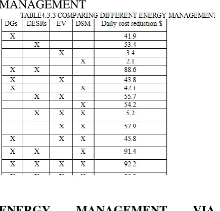
At this stage, each energy management scenario is applied in the multi-micro grid system individually for different cases, and the results in terms of EMSI and total operational costs are investigated.
ENERGY MANAGEMENT VIA DISPATCHABLE BIOMASS
performing energy management. It is seen that optimally controlling the biomass DGs with capacities ranging from 0 to 600 kW, can increase the EMSI from 0 to 88.91%. When all the DGs are optimally controlled for energy management purposes, the daily costs for the utility of operating the DGs only, will be reduced from $319.69 to $35.44, which is a considerable reduction for a single day. If we assume almost the same amount of savings for a period of a whole year or more, we can see that the savings will be great. In order to see how the output of DGs varies during 24 hours in the optimum energy management scenario, the output power of the third and sixth generators are plotted as samples for a case where all six generators are optimally controlled.
ENERGY MANAGEMENT VIA STORAGE UNITS
In this section, only the storage units are considered as control variables to perform energy management. It is assumed that the efficiency of the storage units is 80%, with one charge/discharge cycle occurring every 24 hours at a cost of 0.005$/kWh. It should be noted that, since the purpose of this research is to assess different energy management scenarios, only the costs related to the operation of the devices are minimized and other costs, such as replacements, fixed O&M, etc., are not considered. As shown, by increasing the number of controllable storage units, the EMSI increases.
ENERGY MANAGEMENT VIA DEMAND SIDE MANAGEMENT
The demand-side management is considered as a control option in this section. It is assumed that up to 30% of the loads connected to buses mentioned in Table VII are controllable and can be shifted for up to 6 hours. At each stage, one of the loads is added to the controllable loads, and its impact on the EMSI. It is seen that by increasing the number of
controllable loads, the EMSI increases from 0 to 12.1%. The total daily costs related to the shifting of loads are also reduced from $20.48 to $18.37. The reduction in daily costs is related to the costs that the utility has to pay and clearly the customers’ saving at the controllable buses will be much greater due to the difference in the price of electricity during off-peak and on-peak hours.
TABLE4.3.3
COMPARING DIFFERENT ENERGY
MANAGEMENT
ENERGY MANAGEMENT VIA ELECTRIC VEHICLES
In this section, only the electric vehicles charging and discharging periods for the V2G program are considered as control variables. The V2G program cannot be successful without the active participation of vehicle owners, and the active participation of vehicle owners cannot be obtained without reasonable price incentives.Through the application of the V2G program, the EVs can be ordered to act as generation sources and/or as responsive loads depending upon the state of the power system and of the EVs battery storage systems
ROBUSTNESS OF THE ENERGY MANAGEMENT PROCESS
values of loads and generation for the next 24 hours to plan for the generation and consumption of devices in the multi-micro grid system. This section investigates the sensitivity of the plan in terms of the EMSI and total costs to the prediction error.DGs is 0.12$/win this section, only the dispatchable DGs are considered as control variables for performing energy management.
The prediction error occurs when the actual load/generation data for the next 24 hours differs from what we predicted. For instance, if we assume the load will be 1pu in hour H but it is actually 1.05%, we have a 5% error in load. Therefore, an increase in load/generation prediction error is modeled by increasing- /decreasing the actual load/generation by X% from the predicted load/generation data for each system component. The EMSI is then calculated by using the settings of load/generation devices derived from predicted data by using the actual load/generation data that solar irradiance, wind speed and the Eves’ charge/discharge states are independent, the probability of any combination of load and generation is obtained by multiplying all the probabilities.
The prediction error is considered as both excess and deficit (up or down shift) compared to predicted values of all loads and generation units in the system, and the EMSI and daily costs for the worst cases are plotted in the figures. As shown in Fig. 16, by increasing the load prediction error from 0% to 15%, for the case that all the units are under control, the EMSI. Also, for the same case, by increasing the load prediction error, the total daily costs are increased from $-63 to $- 52. It is seen that by increasing the generation prediction error from 0% to 15%, the EMSI reduces and the daily costs increase. For the case that all devices are under control, the EMSI reduces and the total daily costs are increased from $-63 to $-45 per day.
4.3.4 ENERGY MANAGEMENT VIA ELECTRIC VEHICLES
In this section, only the electric vehicles charging and discharging periods for the V2G program are considered as control variables. The V2G program cannot be successful without the active participation of vehicle owners, and the active participation of vehicle owners cannot be obtained without reasonable price incentives.Through the application of the V2G program, the EVs can be ordered to act as generation sources and/or as responsive loads depending upon the state of the power system and of the EVs battery storage systems
4.4 ROBUSTNESS OF THE ENERGY MANAGEMENT PROCESS
The day-ahead energy management plan, proposed in this project, used the predicted values of loads and generation for the next 24 hours to plan for the generation and consumption of devices in the multi-micro grid system. This section investigates the sensitivity of the plan in terms of the EMSI and total costs to the prediction error.DGs is 0.12$/win this section, only the dispatchable DGs are considered as control variables for performing energy management.
generation is obtained by multiplying all the probabilities.
The prediction error is considered as both excess and deficit (up or down shift) compared to predicted values of all loads and generation units in the system, and the EMSI and daily costs for the worst cases are plotted in the figures. As shown in Fig. 16, by increasing the load prediction error from 0% to 15%, for the case that all the units are under control, the EMSI. Also, for the same case, by increasing the load prediction error, the total daily costs are increased from $-63 to $- 52. It is seen that by increasing the generation prediction error from 0% to 15%, the EMSI reduces and the daily costs increase. For the case that all devices are under control, the EMSI reduces and the total daily costs are increased from $-63 to $-45 per day.
CHAPTER 5
SIMULATION RESULTS
5.1 THE HOURLY PRICE SELLING AND BUYING ELECTRICITY
The result that is acquired between “Hours of the day on x-axis and Cents/kw on y-axis” manifest that the hourly prices for purchasing electricity from vehicle owner varies in different peak loads i.e., off peak, on peak, mid peak.
F.I.G. 5.1THE HOURLY PRICE SELLING AND BUYING ELECTRICITY
5.2VARIATION OF EMSI BY CHANGING NUMBER OF CONTROLLABLE UNITS
The result that is acquired between “Number of units under control on x-axis and emsi (%) on y-axis “its manifest that the variation of EMSI and daily costs for different micro grids with different numbers of controllable units
F.I.G.5.2 VARIATION OF EMSI BY CHANGING NUMBER OF
CONTROLLABLE UNITS
5.3 DAILY COST BY CHANGING NUMBER OF CONTROLLABLE UNITS
The result that is acquired between “Number of units under control on x-axis and daily cost” on y-axis its manifest that the variation of EMSI and daily costs for different micro grids with different numbers of controllable units.
F.I.G 5.3 DAILY COST BY
CHANGING NUMBER OF
CONTROLLABLE UNITS
5.4 EMSI AND DAILY COST BY CHANGING NUMBER OF CONTROLLABLE UNITS
F.I.G.5.4 EMSI AND DAILY COST BY
CHANGING NUMBER OF
CONTROLLABLE UNITS
5.5 DAILY ENERGY LOSSES BY CHANGING NUMBER OF CONTROLLABLEUNITS
The result that is acquired between “Number of units under control on x-axis and daily losses (Kwh) on y-axis” its manifest that the application of the V2G program, the EVs can be ordered to act as generation sources and/or as responsive loads depending upon the state of the power system and of the EVs battery storage systems.
F.I.G 5.5 DAILY ENERGY LOSSES BY CHANGING NUMBER OF
CONTROLLABLE UNITS
5.6 HOURLY VARIATION DG3 AND DG6
The result that is acquired between “Hours of the day on x-axis and dg’s output power(kw) on y-axis” its manifest that the hourly variation of total system loads before and after performing energy management for a case in which six aggregate and six residential EV buses are under control
F.I.G.5.6 HOURLY VARIATION DG3 AND DG6
5.7 EMSI AND DAILY COST CHANGING OF CONTROLLABLE EV BUSES
The result that is acquired between “Ev buses under control on x-axis and emsi (%) on y-axis” its manifest that the EMSI is then calculated by using the settings of load/generation devices derived from predicted data by using the actual load/generation data.
F.I.G.5.7 EMSI AND DAILY COST CHANGING OF CONTROLLABLE EV
BUSES
5.8 VARIATION OF LOAD AT BUS 48 BEFORE AND AFTER DEMAND SIDE
MANAGEMENT
F.I.G.5.8 VARIATION OF LOAD AT BUS 48 BEFORE AND AFTER DEMAND SIDE
MANAGEMENT
5.9 EMSI AND DAILY COST BY CHANGING THE LOAD PREDICTION ERROR
The result that is acquired between “Hourly 10% generation prediction error on x-axis vs emsi error (%) on y-axis”. Its manifest that the total daily costs are increased from $-63 to $52. The impact of generation prediction error on the EMSI.
F.I.G.5.9EMSI AND DAILY COST BY CHANGING THE LOAD PREDICTION
ERROR
CONCLUSIONS AND FUTURE SCOPE
In this undertaking, an enhanced technique for performing energy the board in multi-micro grid frameworks is exhibited. The
examination venture makes new
commitments to the field as far as characterizing another probabilistic record (EMSI) to evaluate the achievement of energy the executives alternatives, considering all energy the board choices (counting probabilistic DGs, DESRs, DSM and EVs) at the same time with the end goal of energy the executives, taking care of the
energy the executives issue for multi-micro grid frameworks and performing appraisals for various energy the executives situations. A contextual analysis is introduced to think about two distinctive energy the board choices for multi-micro grid frameworks. It is appeared in a multi-micro grid distribution framework, performing energy the executives for the entire framework at the same time would be progressively valuable contrasted with performing it independently for each micro grid. It is demonstrated that the all out framework's energy misfortunes will be greatly brought down when energy the executives is performed by and large.
Moreover, through a few affectability examines, it is appeared much of the time, performing energy the board in a multi-micro grid framework does not just cover the controlled gadgets' operational expenses, yet in addition gives the utility money related advantages that may take care of the establishment costs over a significant lot of time. In addition, by all the while performing distinctive energy the board situations (e.g., controlling all generation-/utilization units), the EMSI will increment further and the operational costs will be diminished essentially.
The contextual investigations displayed in this task give an understanding to utility specialists to 1) think about the diverse energy the executives situations in a multi-micro grid framework, and 2) select the suitable energy the board alternative, in view of their necessities, for usage in a multi-micro grid distribution framework.
REFERENCE
[2] Y. Ma; T. Houghton; A. Crude; D. Infield, “Modeling the Benefits of Vehicle-to-Grid Technology to a Power System," IEEE Trans. Power Syst., vol.27, no.2, pp.1012,1020, May 2012.
[3] S. Salinas; M. Li; P. Li; Y. Fu, "Dynamic Energy Management for the Smart Grid with Distributed Energy Resources," IEEE Trans. Smart Grid, vol.4, no.4, pp.2139, 2151, Dec. 2013.
[4] S.ii-keun;J.won-wook; “operaatin schemes of smart distrubition network with distributed energy resources for loss reduction and service restorstion,”IEEE
Trans .smart
grid,vol.4no.1pp367,374,march 2013. [5] I.Atezi;l.g Ordonez;g.sctutari;d.p, “Deamand side management via distributed energy generation and storage optimization,
“IEEE Trans.smart
grid,vol4,no2.,pp866,876,June 2013.
[6] Y. Wu; V.K.N. Lau; D.H.K. Tsang; P. Q. Li; M. Limin, "Optimal Energy Scheduling for Residential Smart Grid With Centralized Renewable Energy Source," IEEE Systems Journal, vol.8, no.2, pp.562,576, June 2014.
[7] Y.S. Foo Eddy, H.B. Gooi, S.X. Chen, "Multi-Agent System for Distributed Management of Microgrids," in Power Systems, IEEE Transactions on, vol.30, no.1, pp.24-34, Jan. 2015.
[8] W. Tushar; B. Chai; C. Yuen; D. Smith; K. Wood; Z. Yang; V. Poor, "Three- Party Energy Management with Distributed Energy Resources in Smart Grid," IEEE Trans. Ind. Electronics, vol.62, no.4, pp.2487,2498, April 2015.
[9] MARTIN ORDONEZ “transaction on power electronics Power electronics is the application solid electronics to the control and conversion of electric power” IEEE
trans.The energy research on applied
science, June 2017
[10] I SEYED ALI AREFIFAR, “planning and operation of smart grids” represents that the smart grid’s complexity will evolve over
time require new technologies for
efficient,IEEE trans.Natural
resourses.,2017.
[11] F. Glover, “Taboo search—P1,” ORSA J. Compute., vol.1, no.3, pp.190– 206, 1989.
[12] F. Glover, “Taboo search—P2,” ORSA J. Compute., vol. 2, no. 1, pp. 4– 32, 1990.
[13] D. Shirmohammadi; H.W. Hong; A. Semlyen; G.X. Luo, "A compensation- based power flow method for weakly meshed distribution and transmission networks," IEEE Trans. Power Syst., vol.3, no.2, pp.753-762, May 1988.
[14] S.A. Aeriform; Y.A.I. Mohamed; T.H.M. El-Foully, “Optimum Micro grid Design for Enhancing Reliability and Supply-Security," IEEE Trans. Smart Grid, vol.4, no.3, pp.1567,1575, Sept. 2013.
[15] F. Kennel; D. Gorges; S. Liu, “Energy Management for Smart Grids with Electric Vehicles Based on Hierarchical MPC," IEEE Trans. Ind. Informatics, vol.9, no.3, pp.1528, 1537, Aug. 2013
[16] M. Zhang; J. Chen, “The Energy Management and Optimized Operation of Electric Vehicles Based on Micro grid," IEEE Trans. Power Delivery, vol.29, no.3, pp.1427, 1435, June 2014.
[17] S. Gao; K. Chau; C. Liu; D. Wu; C. Chan, "Integrated Energy Management of Plug-in Electric Vehicles in Power Grid with Renewable," IEEE Trans. Vehicular Technology, vol.63, no.7, pp.3019,3027, Sept. 2014.
[18] J. Soares; H. Morays; T. Sousa; Z. Vale; P. Farai, “Day-Ahead Resource Scheduling Including Demand Response for Electric Vehicles," IEEE Trans. Smart Grid, vol.4, no.1, pp.596, 605, March 2013.