P a g e
|
390
Design Of Vertical Ballistic Pendulum For Impulse Measurement
1G. Sri Sai Krishna Yadav, 2DR.J. Suresh kumar
1PG Scholar, MTech, Dept of Mechatronics, JNTUHCEH, Hyderabad, T.S.
2Professor, Dept of Mechanical Engineering, JNTUHCEH, Hyderabad, T.S.
ABSTRACT:
This paper presents the design of Vertical Ballistic pendulum for Impulse measurement. The purpose of this pendulum
is to determine the impulse load imparted on the target plate on detonation of buried charge. Landmines are a major
threat to survivability of light weight vehicles. They present a significant challenge to protect platforms because of
the large impulse loads induced from the buried charge. To overcome this problem, the design of survivable platforms
requires the ability to withstand the impulse generated from buried mines. The impulse load that a buried charge
applies on a target plate on detonation is characterized in terms of Vertical Impulse. The vertical impulse is a
function of the size of the charge, its depth of burial, i.e. the distance between the soil surface and the target plate.
The Vertical ballistic pendulum is used to measure the vertical impulse generated. The design structure of pendulum
has to withstand the loads when the target plate is subject to explosion of landmine buried under dry construction
sand. The target plate is clamped with the Vertical Ballistic Pendulum and an arrangement is made between the
supporting structure and ballast pendulum by placing a compression spring to measure the vertical
impulse generated after detonation.
KEYWORDS: - vertical impulse, detonation, size of charge. Etc.
1)Introduction:
-
The presence of landmines in both military areas of war and civilian countryside presents a substantial threat to
human life. Active and passive measures are used to counter these indiscriminate killers. The platforms of the
lightweight vehicles should be protected from large impulse loads, which are generated from the buried charges. The
design of the bottom plate should withstand the large impulse loads when it is exposed to landmine blasts. There is a
need to measure the amount of impulse load imparted on to the bottom plate.
Vertical Ballistic Pendulum is used to measure the impulse load. A test plate of some desired dimension is taken
and attached to a Vertical Ballistic Pendulum,
which is suspended via a tensioned linear spring over the buried charge. The response of test plate is characterized in
terms of vertical impulse. The vertical impulse is a function of the size of the charge, its depth of burial, the distance
between the soil surface and the target, and the properties of the soil in which it is buried. Vertical ballistic pendulum
is thus designed to measure the impulse load. The design made is applicable for different types of loads and used
under various types of environment conditions.
2)Design Procedure:
P a g e
|
391
I= A √kma clamped perimeter of 40 mm width. The target plate is attached to a vertical ballistic pendulum
that is suspended via a tensioned linear spring over the buried charge.
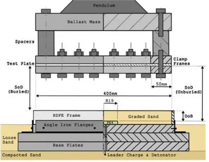
The test setup is shown in the below figure.
The stand-off distance (SoD) is defined as the distance between the target plate and the surface of the sand for
the buried tests, and as the distance between the plate and the top of the explosive for the unburied tests. The
depth of burial (DoB) of the explosive is defined as the height of the sand above the upper face of the explosive
charge.
The explosive charges were buried under dry construction sand. A 420x420 mm frame made 8 mm thick
HDPE (High Density Poly Ethylene) is placed on top of thick steel base plates to create a control volume for the
sand in the experiments. The height of this frame is equal to the sum of the DoB and the height of the explosive
disc. The frame is located on to the base plate by small angle iron flanges.
Cylindrical PE4 ( 21.6% oxygen balance) plastic explosive charges with a constant diameter of 38 mm were
used. The explosive disc is placed flush on the base plate, with the detonator and a 1 g PE4 leader charge located
in a machined hole underneath the disc. The base plate provides a consistent, rigid reflective surface. The 1 g
leader charge ensures consistently
good contact between the detonator and the main explosive charge.
The vertical displacement (A) of the pendulum is recorded by four tracing pens and is used to calculate the
impulse (I) imparted onto the target plate from the explosion (spring stiffness k, pendulum mass m). The below
figure shows the test setup fully configured for a buried charge experiment and ready for detonation. The pendulum,
which is free to rotate, is aligned with the base plate by small HDPE strips placed in opposite corners of the HDPE
P a g e
|
392
I = impulse load to be calculatedA = vertical displacement of the pendulum K = spring stiffness
m = mass of the pendulum
K= mg L0−La
M = mass or load, G = gravity of earth,
Lₒ = final length of spring
Effect of soil on impulse:
The experimental values for impulse and deflection are very less than the predicted values. A number of
factors can explain the large difference between the predicted and measured values. The good agreement found by
Morris (Ref.14) seems to indicate that the mathematical model for the impulse is accurate. However, it is well known
that the effectiveness of the blast mine is extremely sensitive to the soil conditions including temperature, moisture
content, and type of soil (e.g. sand and clay). Higher
water content, for example, results in a stiffer, more incompressible soil that directs more of the explosive energy
upwards. Soil with lower density absorbs more energy of the blast resulting in less damage to the structures over
detonation. It is indicated that the ground shock wave intensity varies by two orders of magnitude depending on the
soil and the moisture content.
3)
Progress till date: -
Scaling of the variable parameters:
As we have the formula to calculate the vertical impulse on a horizontal plate due to buried charges, we need
the values for the variable. The Buckingham 𝜋-theorem is used to generate a complete set of dimensionless 𝜋-terms,
P a g e
|
393
for the independent variables of the ICV are used to calculate the scaled values of same variables for the apparatus.
Parametric values for the ICV:
S = 450 mm D = 100 mm
Mass of TNT charge = 8 kg
Assumptions:
1. The plate used in the ICV is of aluminium foam. The plate, which serves as blast deflector in the mine blast
pendulum, is assumed hypothetical members, which is perfectly rigid and has same material properties as that of
aluminium foam including the density
.
2.In the real case when the blast takes place, the plate made of any material undergoes deflection and absorbs some
part of the energy that is imparted to the plate as impulse during explosion.
3.Since the main objectives of this project is to design the spring, it is assumed that plate does not absorbed energy
that is the plate is completely rigid and as there is no information regarding which plate is going to be used, the
properties of the material are assumed to be same as that of aluminium foam.
4. Since the impulse is directly properties to square root of the soil density, lager impulse will be witnessed for higher
density soil. Hence, it has been searched for the maximum density of the density of the naturally available soil. It has
been found that the density is 2235kg/m3.
5.The TNT charge assumed to be cylindrical in shape with a height that is on third of the diameter.
6. It is assumed that the axis of the charge cylinder coincides with the geometric center of the horizontal plate.
7. The total energy imparted onto the plate during explosion is converted into gravitational potential energy of the
plate and potential energy in the spring at the maximum deflection point. the losses in the foam of the sound are
neglected
SCALING:
On using the equality of the dimension 𝜋– term and the above assumption, the scaled parametric values are
Mass of TNT = 1 gm SoD = 178.65 mm DoB = 22.5 mm
Spring Design Material Selection:
Chrome Vanadium is used as the spring material because it is
P a g e
|
394
Compression Spring:From the fundamental understanding of the free body diagram of a compression spring one can see that any
section of the spring is experiencing a torque and a force. Shear force will always be associated with the bending
moment. However, in an ideal situation when the force is acting at the center of the circular spring and the coils of the
spring are almost parallel to each other, no bending moment would result at any section of the spring. Compressive
axial loads are applied. Though the load on the spring is compressive, the spring wire is under torsion, as the load on
any coil tends to twist the wire about its axis.
The allowable stress of a spring that has been set is significantly higher than that of an as-wound spring. Ks is
used to calculate the stress in a set spring
because for static loading the yielding during setting relieves the curvature stress concentration. The curvature effect
is nullified on set removing. In some cases, residual bending stress are present as well. In such cases bending stress
becomes negligible after set is removed.
If a spring is compressed to a given stress level and released instantaneously, the maximum spring velocity
is the stress divided by 35.5. Similarly, if the spring is loaded at known velocity, the instantaneous stress can be
calculated by the conventional equation. This will limit design performance. Since the surge wave travels the length
of the spring, springs loaded at high velocity often are subjected to resonance.
Assumptions:
1.Closed coil helical compression spring is used.
2.Spring is set removed.
3. A clash allowance of 15% is used for spring stability.
4.The spring is squared and grounded.
5.A maximum deflection of 156 mm is assumed.
6. Though the spring experiences impact loading, design has been done for the static loading case with the load to be
the force on the spring at maximum deflection. The velocity of the plate initially is 8.225 m/s and it is zero at the
maximum deflection point. So due to surging, the spring experience maximum stress at the initial stage and
instantaneous stress is 291.99 Mpa and the spring with stand this stress if the allowable stress is more than this
value.For Chrome Vanadium Steels with wire diameter more than 12 mm, the Ultimate Tensile Strength is between
1300 Mpa and 1450 Mpa. Sut is taken to be 1300 Mpa.
REFERENCES
P a g e
|
395
2. „The response of quadrangular plates to buried charges‟, International Journal on Impact Engineering.
3. Westine, P.S., Morris, B.L., Cox, and Polch, E.Z., “Development of computer Program for Floor Plate
Response from Land Mine Explosion”, Technical Report No. 13045, US Army Tank-Automotive Command,
Warren, MI, January, 1985.
4. „A numerical analysis of the effect of surrogate Anti-Tank Mine Blasts on the M113‟, DREV TM-2000-07,
by K. Williams,
K. Poon.
5. „Impulse on Blast Deflectors from a Landmine Explosion‟, DREV-TM-9814, by
J.E. Tremblay.
6. „Scaling of the deformation histories for clamped circular plates subjected to blast loading by buried
charges‟, International Journal Of Impact Engineering, by Xing Zhao.
7. „Standard handbook of Machine Design‟, by Joseph E. Shigley.
8. „Machine Design, an Integrated Approach‟, by Robert L. Norton.
9. „Numerical Analysis of the Buried Mine Explosions with Emphasis on Effect of soil Properties on Loading‟,
Defence College of
Management and Technology, Cranfield University.
10. „Impulsive Loading Events and Similarity Scaling‟, I.M. Snyman, Journal on Engineering Structures.
11. „Vertical Impulse Measurement of mine Buried in Saturated sand‟, „Frag blast: International Journal for Blasting
and Fragmentation‟, LC Taylor, RR Skaggs and W Gault.
12. „Impulse Loading Resulting From Shallow Buried Explosive in Water-Saturated sand‟, M Grujide, B
Pandurangan, Y Huang, B A Cheesemen, W N Roy, R R Skaggs.
13. „Dynamic Response of Compressor Valve Springs to Impact Loading‟, O. Yang, P. Engel, B.G. Shiva Prasad,
D. Woollatt.
14. Morris, B.L., “Analysis of Improved Crew Survivability in Light Vehicles Subjected to Mine Blast, Volume 1 –
Technical Report”, SwRI Project No. 06-5095, Technical Report to U.S. Army Belvoir Research, Development