SHAPE RECOGNITION OF SHALLOW BURIED METAL-LIC OBJECTS AT X-BAND USING ANN AND IMAGE ANALYSIS TECHNIQUES
D. Singh, N. K. Choudhary, and K. C. Tiwari
Department of Electronics and Computer Engineering Indian Institute of Technology Roorkee
Roorkee 247667, India
R. Prasad
Department of Applied Physics Institute of Technology
Banaras Hindu University Varanasi, India
Abstract—A robust algorithm has been developed for improving the backscattered signal and recognizing the shape of the shallow buried metallic object using Artificial Neural Network (ANN) and image analysis techniques for remote sensing at X-band. An ANN with image analysis technique based on tangent analysis is proposed to recognize the shape of metallic buried objects and minimize the orientation effect of buried object. The experimental setup has been assembled for detecting the buried metallic objects of any size at different depths in the sand pit. The system uses only one pyramidal horn antenna for transmitting and receiving microwave signals at X-band (10.0 GHz). All the data to be processed by this algorithm has been received by moving the transmitter/receiver to different locations at a single frequency in X-band in the far field region. ANN technique has been found to be very efficient. An effective training technique has been used to improve the effectiveness of the algorithm. The retrieved result of shape is in good agreement with original shape.
1. INTRODUCTION
A lot of researchers from various fields (like archaeology, criminology, military, geophysical exploration, submarine detection etc.) are involved in the detection of buried objects. Microwave radar is known to be the most likely answer to these detection problems except submarine detection where acoustic detection finds maximum use [1–3]. Brunzell [4] describes use of pulse radar for detecting buried object. In subsurface detection, when exploring with X-band of microwave, the nearest target is usually at a distance of about 1 meter, maintaining the sanctity of the far field antenna. Hence pulse radar must have extremely high precision in time domain, making it quite expensive. CW radar with low frequency modulation can be used for subsurface detection, keeping system cost low. However CW radar does not provide range information. FM-CW radar is a cheaper alternative to pulse radar, if information about depth of object is needed. Yamaguchi [5–7] described the use of FM-CW radar for detecting human body buried in wet snow pack. Carin [8] described the use of polarimetric synthetic aperture radar (SAR) radar for detecting landmines.
All the above mentioned investigation mainly concentrated on detecting buried objects. Considering the problem of detecting landmines with the help of data obtained by radar, there are possibilities of a large number of false alarms due to stones, tree roots etc. A typical war field will usually contain many metal fragments. These objects will interfere with the detection of landmines. Some method is needed which will classify the detected objects. Various image processing techniques have been found extensive use and have increased the confidence in detection of the shape of object, and hence classify them. However these techniques are found to be ineffective when backscattered signal quality is poor (i.e., includes noise with surroundings) [1–8].
distributed computing platform that does not need programming like conventional computers. Instead neural networks learn from sample examples and due to generalization property, they are able to correctly solve instances of problems not used during learning. The complexity of the problem increases because of the lossy nature of the medium between air and the dielectric object under consideration. The precise detection of land mines, unexploded ordnances, plastic pipes etc. are some of the major challenges to the researchers [13, 14]. Since mechanical probing of soil is not possible in every case and is impractical in some of the cases. That’s why the importance of GPR (Ground Penetrating Radar) has greatly increased. But the distance from the object is limitation of GPR.
of the present paper.
2. METHODOLOGY
2.1. System Overview and Measurement Procedure
Isolator PAD
Sand pit Circulator Movable Platform
Microwave Source
Power meter
1.5 m
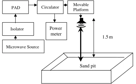
Figure 1. Schematic diagram of monostatic scatterometer.
A monostatic radar (scatterometer) has been used for the detection of buried object as shown in Figure 1 and specifications are given in Table 1. Any radar that measures the scattering or reflective properties of surfaces or volumes is called a scatterometer. Thus a scatterometer may be radar specifically designed for backscattering measurement; or it may be radar designed for other purposes such as imaging or altimetry, but calibrated accurately enough so that scattering measurements with it is possible [16, 17]. Scatterometers may be designed to make measurements at a particular angle,
Table 1. System parameters.
Central Frequency 10.0 GHz Frequency Band Width 0.8 GHz
Antenna type Dual Polarized Pyramidal Horn Antenna Beam Width 18.5 degree
Antenna Gain 20 dB
frequency, and polarization. All the observations have been taken at a frequency of 10.0 GHz with a plane polarized wave (Horizontal-Horizontal polarization) incident normally on the target. A pyramidal horn antenna has been used as both transmitter and receiver. It has been mounted on a movable platform which can scan the region under investigation in two dimensional spaces in steps of 5 cm. These objects were buried at the center of the sandpit which dimension was 2.0 m ×2.0 m. The size of the object (Aluminum sheet) was 59.2×59.2 cm2. The same sample was kept at different depths (0.5 cm to 2.5 cm at interval of 0.5 cm) into the sandpit. Every time care was taken to fill-up the sandpit and levels it up and leveling was done by the level profiler. Adequate care is taken every time in filling the sand pit and leveling it up. The surface is assumed smooth at 10.0 GHz frequencies and sand was dry with dielectric constant approximately 3.5 during whole experiment. The observations were taken in far field zone. The calibration of the system was checked before and after each scan with a view to ascertain the truthfulness of collected data [16]. The back scattered signals received have been processed to get better image of buried object.
2.2. Image Enhancement
An ANN (Artificial Neural Network) technique has been used for the processing of signals received. A neural network is network of a number of simple processors with a small amount of local memory. These processors are connected by unidirectional communication channels that carry numerical data. It is like brain as knowledge is acquired by the network through a learning process. It is a parallel distributed network with following features [18–20]:
• A set of processing units.
• An activation state for each unit, which is equivalent to the output of the unit.
• Connection between units. Each connection is defined by a weight wjk that determines the effect that the signal of unitj has on the
unitk.
• A propagation rule, which determines the effective input of the unit from its external inputs.
• An activation function, which determines the new level of activation based on the effective input and the current activation.
• An external input (bias, offset) for each unit.
• A method for information gathering (learning rule).
A neural network has three types of units as shown in Figure 2 [19]:
Output Layer
Input Layer
Figure 2. A single-hidden-layer multilayer perceptron neural network (MLPNN).
• Input units: Receives data from outside of the network.
• Output units: Send data out of the network.
• Hidden units: Its input and output signals remain within the
network.
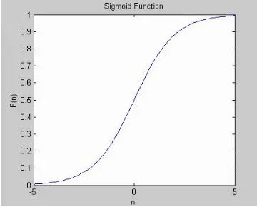
Sigmoid function has been used as activation function. It is easy to differentiate and thus it can easily reduce the computation burden for training. It provides the output level in the range of 0 to 1 as shown in Figure 3.
Figure 3. Sigmoid function.
F(n) = 1
The Error Back Propagation (EBP) algorithm in ANN has been used in this paper which is as following [18–20]:
Step1: Initialize the weights wij. Set learning rate η(0 < η ≤1). It determines how quickly the back propagation algorithm converges toward the solution.
Step2: Set bias input as unity.
Step3: Outputs at the nodes of hidden layer and output layer.
Uj =F
K
k=1
WjkX(k)
(2)
and
Ui =F ⎛ ⎝J
j=1
WijUj
⎞
⎠, (3)
whereF is sigmoid function.
Step4: Errors for each node is calculated as:
δi = (O−Ui)Ui(1−Ui) (for the output cell) (4)
δj = I
i=1
(Wijδi)Uj(1−Uj) (for hidden cell) (5)
Here O is the desired output and Ui is the actual output of the output layer. Wij is the weight connecting jth node to ith node Uj is the input to the jth node and I is the number of output
nodes.
Step5: Weights are updated to minimize the error as follows: W∗
ij = Wij∗ +ηδiUj (Hidden to output layer) (6)
Wjk∗ = Wjk∗ +ηδjX(k) Input to hidden layer (7)
Step6: Test stopping criteria:
Continuous update: Weights are updated for each input output
pair.
Ec = 0.5∗
m
i=1
[O−Ui]2 (8)
Batch update: Weights are updated after the presentation of all input output pairs in the training set.
Eb = N1 N
n=1
If error is smaller than a specific tolerance or the number of iterations exceeds a specific value then stop otherwise go to Step 3.
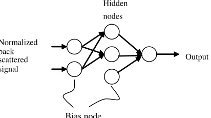
The proposed system consists of one input node, one output node and a hidden layer with two nodes as shown in Figure 4. Input to the system is a normalized back scattered and output is the signal with reduced noise level in backscattered signal.
Normalized back
scattered Output
Hidden nodes
Bias node
signal
Figure 4. Network used for reducing noise level in backscattered signal.
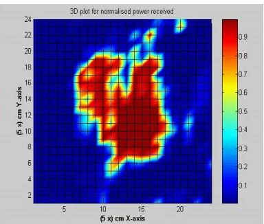
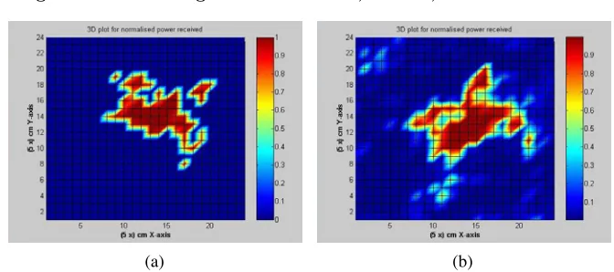
the system is efficient enough to know the desired level of output for a given input signal. This technique has been found to be very efficient in estimating the back scattered signal up to a satisfactory level. The reduction of noise in backscattered signal can be seen by observing the Figures 5 and 6, where depth of object was 2.0 cm. It is clearly observe that the noise is quite reduced in Figure 6. Weights obtained for this case are as following:
Parameters
Connection between Input Layer and Hidden Layer (Numbers of input nodes = 1
and hidden nodes = 2)
Connection between Hidden Layer and Output layer (Numbers of hidden nodes = 2
and output nodes = 1)
Weights −5.3294, 5.1258 6.7058, 6.2467
Bias 2.4197,−2.4402 −0.0448
Figure 5. Original back scattered signal received by the monostatic scatterometer.
2.3. Shape Recognition
Determining the shape of the buried object or the area over which the objects are buried is one of the major challenges to the researchers. Determining shape, dimension, area etc. of the mine fields are urgent requirements for military purposes. It’s usually very tough to get an idea about shape of the buried objects or distribution of pipes when the area to be scanned is very large.
algo-Figure 6. Back scattered signal after processing with ANN technique.
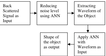
rithm is also less and has been found to be very efficient in determining shapes of the buried objects. The major advantage to this algorithm is that ANN is used which learns through instances. The system has been trained for different shapes by extracting the property of wave-form of each object. Each object provides different wavewave-form according to its shape. Another advantage to this system is that the system is not restricted only to the recognition of ordinary shapes like square, rectangular or circular but can be used to recognize any type of shapes. Since each object provides different type of waveform, so a particular type of waveform can be used for recognizing a particular shape. At first all the backscattered signal obtained by scanning the target in 2D space are processed by ANN and then stored in a 2D matrix. To extract the waveform, every element in the rows and then the columns are added. Now a graph may be obtained as the summed value of ele-ments vs. rows and columns. This waveform will provide the identity of the shape of a buried object. This waveform will be fed to the sys-tem as input for determining the shape of the object. Since each shape provides different waveform and thus the system can be trained with different waveform for different objects. The accuracy of the system is almost in user’s hand. Better is the training data better will be the system. Figure 7 shows the flow chart to detect the shape with ANN and image analysis approaches.
Back Scattered Signal as Input Reducing noise level using ANN Extracting Waveform of the Object Apply ANN with Waveform as Input Shape of the object as output
Figure 7. Block diagram of the system for recognizing the shape of the metallic shallow buried object without consideration of orientation effect.
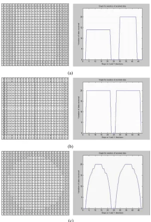
ANN with one hidden layer with two nodes has been used. The number of output nodes depends upon the types of different shapes like square, rectangle etc. to be recognized and the number of input nodes depends on the total number of columns and rows of the matrix of the backscattered signals received by scanning the target. Now the weights obtained after training the system for square and rectangular shapes are as following:
Parameters
Connection between Input Layer and Hidden Layer (Numbers of input nodes = 48
and hidden nodes = 2)
Connection between Hidden Layer and Output layer (Numbers of hidden nodes = 2
and output nodes = 2)
Weights
1.0000, 1.0000, 7.3678, 7.4076,−2.5339,−0.8830,
−1.3309,−1.2697, 1.8762, 0.7028,−11.1180, 3.5080,
−10.2019, 15.6419,−15.6419,
−1.9240,−3.0137,−1.4876,
−1.6238 13.7175,−0.2046, 9.7369, 10.9103, −2.2610, 0.7892,−0.3943,−1.6595,
−7.9682,−8.0080,−1.1081,
−0.7258,−0.7258, 1.8606, 2.9162, 4.8335, 5.8013,
6.1469, 7.3304 6.3104, 5.1210, 3.2435,−3.1432, 3.0779,−5.0559,−6.2529,
−10.4535,−4.1448,−3.3301
7.4835,−7.4835, 7.4835, and 7.4835
(a)
(b)
(c)
One of the major hurdles in recognizing the shape of the buried object is orientation of the object. It is almost impossible to have the object in desired orientation while scanning the target. If, it is tried to find the waveform of such an object then it will be completely different from desired one and will be unable to recognize the shape of the object. That’s because of the fact that the waveforms which have been used for training, are for a particular orientation of the object. This problem can be solved by bringing the object in required orientation from which all the training data have been obtained.
The tangent calculation technique has been proposed for finding orientation of the buried target.
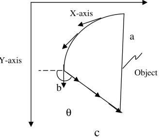
Firstly outer boundary of the image has been obtained and then tangent has been calculated at each point. This will help in determining any straight line in the image. As shown in the Figure 9, an object abc has been considered and is placed in a 2D space. Now tangents have been calculated at each point and adjacent slopes are matched with each other. From a to b slopes are constantly changing but for b to c the change in slope is constant. This helps in determining a straight line and its slope. A threshold may be set for the number of equal slopes to determine the straight line. The main advantage of this technique is that we need not to track the whole boundary of the image and thus avoid unnecessary calculations. As soon as one gets the straight line, the algorithm will terminate.
X-axis
a
Object
b
Y-axis
c
θ
Figure 9. An object placed in 2D space.
P*(x*,y*)
Y- axis P(x,y)
X- axis
θ ϕ
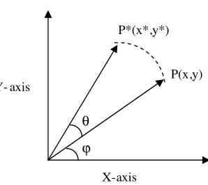
Figure 10. Rotation of point P to pointP∗.
Considering any point P(x, y) making any angle with X-axis as shown in Figure 10. Now the new point obtained by rotating P(x, y) by an angle of θ, will beP∗(x∗, y∗) where,
x∗= (xcosθ−ysinθ) (10) and
y∗= (xsinθ+ycosθ) (11) This transformation has been applied to each and every pixel of the image. The image can be easily rotated to the desired position. The proposed algorithm is shown in Figure 11 and it is giving satisfactory results even after rotating the image by an angle of θ. Figure 12(a) shows the image before any rotation and Figure 12(b) shows the image obtained after rotation and both images represent the similar type of shape. A clear shape of the sheet is not visible because of the possibility of errors in the leveling of the sheet or some error in observations but in the program output, it clearly tells about shape i.e., square rectangle or circle.
Back Scattered Signal as Input
Reducing noise level using ANN
Extracting Outer Boundary of the Image
Searching for Any Straight Edge in the Image
Getting the Slope of the Straight Edge Rotating the
Image by that Slope Extracting
Waveform of the Object Apply ANN
with Waveform as Input Shape of
the object as output
(a) (b)
Figure 12. (a) Enhanced image obtained without rotation, (b) Enhanced image obtained after rotation.
3. CONCLUDING REMARKS
The fusion of image analysis techniques with ANN approach have been developed to recognize the shape of shallow buried metallic objects at 10.0 GHz which is buried in sand and upper surface is assume smooth at 10.0 GHz frequency. The use of lower frequency may provide more accurate information regarding the exactness of the buried objects because attenuation increases with increasing in the frequency. The orientation effect of buried target has been neutralized by proposing tangent calculation technique. A quite good agreement of retrieved shape and real shape has been obtained. The proposed algorithm is useful to any size and maximum shapes of the buried metallic target.
ACKNOWLEDGMENT
The authors would like to thank the ARMREB, Government of India, Ministry of Defense, Armament Research Board, Delhi, India for their financial support in performing the measurements and developing the R & D facility in the department.
REFERENCES
1. Ulbay, F. T., R. K. Moore, and A. K. Fung, Microwave Remote Sensing (Active and Passive), First Ed., Vol. 3, Ch. 14, Addision-Wesley, New York, 1981.
V. T. Nguyen, and A. Eriksen, “Automatic detection of buried utilites and solid objects with GPR using neural networks and pattern recognition,”Journal of Applied Geophysics, Vol. 43, 157– 165, 2000.
3. Carosi, S. and G. Cevini, “An electromagnetic approach based on neural networks for the GPR investigation of buried cylinders,”
IEEE Geoscience and Remotes Sensing Letters, Vol. 2, No. 1,
2005.
4. Brunzell, H., “Detection of shallowly buried objects using impulse radar,”IEEE Trans. Geosci. and Remote Sensing, Vol. 32, No. 2, 875–886, March 1999.
5. Yamaguchi, Y., Y. Maruyama, A. Kawakami, M. Sengoku, and T. Abe, “Detection of object buried in wet snowpack by FM-CW radar,”IEEE Trans. Geosci. and Remote Sensing, Vol. 29, No. 2, 201–208, March 1991.
6. Franceschetti, G. and R. Lanari, Synthetic Aperture Radar Processing, CRC Press, 1999.
7. Yamaguchi, Y., M. Mitsumoto, M. Sengoku, and T. Abe, “Synthetic aperture FM-CW radar applied to the detection of objects buried in snowpack,” IEEE Trans. Geosci. and Remote Sensing, Vol. 32, No. 1, 11–18, January 1994.
8. Carine, L., R. Kapoor, and C. E. Baum, “Polarimetric SAR imaging of buried landmines,” IEEE Trans. Geosci. and Remote Sensing, Vol. 36, No. 6, 1985–1988, November 1998.
9. Christodoulou, C. and M. Georgiopoulos, Application of Neural
Networks in Electromagnetics, Artech House, Boston, London,
2001.
10. Yoshida, T. and S. Omatu, “Neural network approach to land cover mapping,” IEEE Trans. Geosci. and Remote Sensing, Vol. 32, No. 5, 1103–1109, September 1994.
11. Tsintikidis, D., J. L. Haferman, E. N. Anagnostou, W. F. Karjew-ski, and T. F. Smith, “A Neural network approach to estimating rainfall from spaceborne microwave data,”IEEE. Geosci. and Re-mote Sensing, Vol. 35, No. 5, 1079–1093, September 1997.
12. Bischof, H. and A. Leonardis, “Finding optimal neural networks for land use classification,” IEEE Trans. Geosci. and Remote Sensing, Vol. 36, No. 1, 337–341, January 1998.
13. Morrow, I. L. and P. Gendern, “Effective imaging of buried dielectric object,” IEEE Trans. Geosci. and Remote Sensing, Vol. 40, 943–949, 2002.
“Ultrawide-band synthetic aperture radar for detection of unexploded ordinance: Modeling and measurement,”IEEE Trans.
Antennas Propagat., Vol. 48, 1306–1315, September 2000.
15. Tiwari, K. C., D. Singh, and M. K. Arora, “Development of a model for detection and estimation of depth of shallow buried non-metallioc landmine at microwave X-bang frequency,” Progress In Electromagnetic Research, PIER 79, 2008.
16. Currie, N. C., Editor, Radar Reflectivity Measurement:
Tech-niques and Application, Artech House, Norwood, MA, 1989.
17. Ulbay, F. T., R. K. Moore, and A. K. Fung, Active and Passive
Remote Sensing, Vol. 1, Artech House, Norwood, MA, 1982.
18. Simon, H.,Neural Networks, Prentice Hall, New Jersey, 2001. 19. Zurada, J. M., Introduction to Artificial Neural Systems, 2nd
edition, Ch. 4, 163–219, Jaico Publishing House, Mumbai, 1997. 20. Hassoun, M. M., Fundamentals of Artificial Neural Networks,
Ch. 6, 284–295, Prentice-Hall of India, New Delhi, 1999.