A Proposed Control Strategy to Improve the Low Voltage Ride
through Capability of Pv System
Dipak Soni
& Dr. Samina Elyas Mubeen
1
P.G Scholar, EEE Department, Radharamam Engineering College, Bhopal
2
H.O.D, EEE Department, Radharamam Engineering College, Bhopal.
Abstract:
In modern electric power systems, the dependence on solar power is increasing. The grid connected applications are very important with the deficit in conventional power stations due to fuel shortage. This paper focuses on controller design and implementation in grid connected PV systems for low voltage rid through (LVRT) in distribution power systems, this paper proposes a control method to keep the dc-link voltage of PV system constant during low voltage rid through (LVRT). This is done by changing the operating point on the I/V curve of the PV cell from the MPPT point to another point, the active power output of the PV will decrease from the maximum to the needed value. The proposed control system is evaluated under different fault scenarios to test the validity of the control system. The results show that the proposed control system gives the expected performance. The PSCAD package is used for simulating this study.
Keywords
Control system, Photovoltaic systems, Low voltage ride through, Distribution system, PSCAD
1.
Introduction
In recent years, more efforts have been made on the integration of PV systems into the grid in order to meet the imperative demand of a clean and reliable electricity generation. Electric power generation through solar energy process is one of the more methods available at the moment, during the operation of solar energy systems do not generate any greenhouse gas pollution of the environment [1]. The high penetration of PV energy into the power system has resulted in power system operators revising the grid codes requirements for interconnection of this type of generation.
A special focus in these requirements is drawn to the PV fault ride-through capability (LVRT), which addressed primarily the design of the PV controller in such that PV is able to remain connected to the network during abnormal operation condition as well as can contribute to voltage support during and after the abnormal operation conditions. LVRT capability is defined as the PV system should stay connected to the grid in the event of grid failures and injects reactive power to help the grid during the grid fault [2].
There are many researches dealt with the performance of grid-connected PV system under various fault conditions. In [3], the high penetration of PV have effect
on the reactive power supplied by the PV plant. During the fault, the control strategy makes the PV system is capable ride the drop voltage and support the grid by injecting the reactive current. As a result to inverter limit, the active current will decrease to avoid over current. The unbalanced power between grid side and PV side causes increasing of the DC-Link capacitor voltage which causes semiconductor devices damage [4]. Also, the excessive of DC voltage and excessive AC currents causing inverter disconnection [5].
To maintain the DC-link voltage constant, dc-chopper circuit between the inverter and the DC-Link is used in [6] to absorb the power at DC side and to maintain the power balance. In [7], the performance of LVRT control strategy is improved by using the super capacitor at the DC side. The super capacitor is used to absorb extra input power or to compensate the shortage of the output power. Nowadays, PV control strategies are developed in order to reader that the PV system acquires LVRT capability when the faults occur in the grid [8].
The super capacitor can coordinate with the PV system internal power at normal operation. At fault mode, the super capacitor absorbs energy at the DC side and balances the power to avoid changes to DC bus voltage [8]. Unfortunately using the DC chopper circuit and the super capacitor as a hardware protection for DC-Link capacitor increases the cost. In this paper, LVRT of PV in distribution power systems with keeping the DC link voltage to be constant by internal control is achieved. Three LVRT techniques for the PV are simulated and compared.
2.
Grid codes
Fig. 1. LVRT requirement for PV system of E.ON
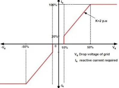
For the E.ON as shown in Fig. 1. The PV inverter should stay connected to the grid when the voltage drops to 0 V for 0.15 seconds and inject some reactive current into the grid. Fig. 2 shows the grid requirement and the relationship between the voltage drop and injected reactive current.
Fig. 2. Voltage support requirement under grid fault for PV system
3.
Modeling of grid-tied PV system
The overall model of grid-tied PV system is shown in Fig. 3 including a PV source, a DC-link capacitor for minimizes the voltage ripple across the PV terminals, a DC-DC converter, a DC-DC controller with maximum power point tracking (MPPT), the grid interface inverter for convert the DC output power of the PV system to a three phase AC power through Pulse Width Modulation (PWM), using Insulated-Gate Bipolar Transistors switches (IGBTs), an appropriate inductance filter to remove the high order harmonics from the voltage and the current of the inverter, and step up transformer with wye grounded winding connection type at the inverter side and delta winding at the grid side.
Fig. 3. Grid-tied PV model.
3.1
PV source model
The solar cell is a semiconductor device that converts the solar radiation directly to electrical energy, with no pollutant emission. The output from a single cell is not suitable for practical cases. To obtain sufficient voltage the cells are connected in series. To obtain sufficient current, they are connected in parallel to form a PV module. The modules can be also connected in series and in parallel to form a PV array with the required rated power [10], [11]. In this paper, a 150 kW PV system is investigated. The equivalent electrical circuit of a PV cell which contains a current source anti-parallel with a diode, a shunt resistance, and a series resistance as shown in Fig. 4 [11], [12].
Fig. 4. The PV cell equivalent circuit.
The basic equation that characterizes the solar cell I/V relationship can be derived after apply Kirchhoff's current law on PV cell equivalent circuit as;
I = Isc − Id − Ish (1)
3.2
DC -DC converter
power switch that is followed by an inductor, a diode and output capacitance [11], [13], as shown in Fig. 5.
Fig. 5. DC -DC step down converter model.
3.3
DC-DC converter controller with (MPPT)
The relationship between current and voltage of the PV cell is non-linear. There is an unrivaled point on the I/V curve, called the Maximum Power Point (MPP), at which the entire PV system operates with maximum efficiency and gives its maximum output power. The location of the MPP is not known, but it can be determined, either through calculation models or by search algorithms in order to maintain the PV array's operating point at its MPP.
The optimum operating point of solar cells occurs at the knee of the I/V curve. In this paper the incremental conductance algorithm is used. This method tracks the peak power under fast varying atmospheric condition. In this method the derivative of PV output power with respect to its output voltage is calculated (dP/dV). When dP/dV approaches zero the maximum PV output power can be achieved [11], [14]. The controller calculates dP/dV based on the measured PV incremental output power and voltage. If dP/dV is not close to zero, the controller will adjust the PV voltage step by step until dP/dV approaches zero, at which the PV array reaches its maximum output.
The mathematical description of this method is illustrated using;
P = V I (2) With incremental change in current and voltage, the modified power is given by [11], [15];
P+ΔP = (I+ΔI). (V+ΔV) (3) After ignoring small terms, equation (3) is simplified to;
ΔP = ΔV.I +ΔI.V (4) ΔP must be zero at peak point. Therefore, at peak point equation (4) becomes;
𝑑𝐼/𝑑𝑉= - I/V (5) The incremental algorithm is based on the following equation holds at the MPP [14]:
𝑑𝐼/𝑑𝑉 + (I/V) = 0 (6)
3.4
Control of inverter without LVRT
Type-style and Fonts
The inverter control system of PV uses two PI controllers [16]. The PI controller is most widely and commonly used controller in the process industry because the number of parameter to adjust in PI controller is very small and many tuning methods and algorithms are available that can be implemented for parameter adjustment [5], [17], [18]. The features of PI controller are: The proportional term (k) immediately impacts controller bias or null value based on the size of the error signal at a particular time, also the past history and current trajectory of the controller error have no influence on the proportional term computation.
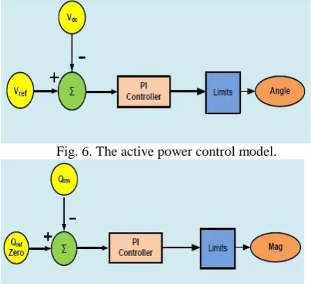
The integral term (t) continually sums up error, through constant summing integral action accumulates influence based on how long and how far the measured process variable has been from set point over time. The first PI controller controls the active power (P) of PV by adjusting the DC bus voltage between the DC-DC converter and the inverter. The active power control model is shown in Fig. 6 [16]. The second PI controller controls the reactive power (Q) to be zero. The reactive power control model is shown in Fig. 7 [16]. The output of the controllers Angle and Magnitude will be also used as an input to the firing pulse generator of the inverter using PWM control technique.
Fig. 6. The active power control model.
Fig. 7. The reactive power control model.
4
LVRT control strategy of the PV system
parameters of PI controllers of active and reactive power are determined using try and error method [19].
(a) A proposed active power control
(b) A proposed reactive power control
Fig. 8. The proposed LVRT control
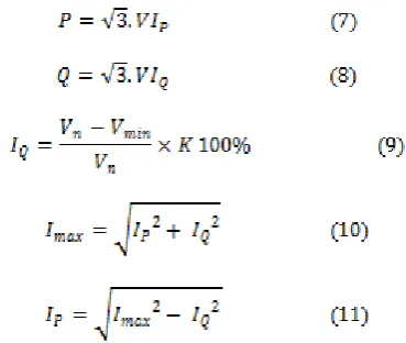
The model has stable responses at steady state and fault conditions. The proportional and integral gains of each PI controller When the fault occur, the protection system detects the fault and transfers the control mode from the normal mode operation to the LVRT mode. Through the LVRT mode, the control system of the PV will operate with new active and reactive power reference values. These reference values can be calculated using equations (7)-(9) which are listed in [20] under LVRT requirements of PV system. The LVRT requirements state that the PV must inject reactive power to the grid in order to support grid voltage during the grid fault without exceeding the PV inverter rating. The amplitude of the injected reactive current , 𝐼𝑄 , must not exceed the maximum inverter current , 𝐼𝑚𝑎𝑥 , to protect the inverter from over load as listed in equations (10) and (11) [20]. The overall LVRT scheme used for determining the active and reactive power reference values is shown in Fig. 9 [20].
Fig. 9. The LVRT reference of active and reactive power calculation
Where 𝐼𝑃 is the active current, 𝐼𝑄 is the reactive current, 𝑉𝑛 is the nominal voltage in pu, 𝑉𝑚𝑖𝑛 is the minimum voltage drop during the fault and K=2.
The grid voltage is measured and compared with the nominal voltage then the difference between the two values is divided by the nominal voltage to get the percentage voltage drop during the voltage. The percentage voltage drop is multiplied by factor (K) which is defined by the grid code to get the reference reactive current that should be injected to the grid according to the grid code.
The reactive power reference is then calculated using equation (11) in pu and then multiplied by the PV rating (VA) (S rated). The reference active current (𝐼𝑃) can be calculated using equation (14). The new reference active power is then calculated using equation (10) in pu and then multiplied by the PV rating (VA) (S rated) to get the value in Volt Ampere.
during the fault [6]. In this paper, a DC-link voltage control system is proposed to keep the DC-link voltage constant during the fault without using a DC-chopper. The proposed DC-link voltage control system is shown in Fig. 10. It consists of two operating modes. The first one is the normal operation mode. The objective of this mode is to extract the maximum power from the PV system by operating at a maximum power point. The second is the fault condition mode. The objective of this mode is to make the PV system generates active power equal to the active power injected to the grid in order to keep power balance at the two sides of the DC-link and meanwhile keeps the DC-link voltage constant.
Fig. 10. The proposed for DC-link voltage control system
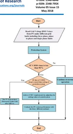
5. The operation flow chart of the PV
The operation flow chart of the PV system under different modes of operation including the proposed control strategy is shown in Fig. 11.
Fig. 11. The operation flow chart of the PV system with the proposed control
6. Related Work
Y. Yang, et.al. Present [2] the progressive growing of single-phase photovoltaic (PV) systems makes the Distribution System Operators (DSOs) update or revise the existing grid codes in order to guarantee the availability, quality, and reliability of the electrical system. It is expected that the future PV systems connected to the low-voltage grid will be more active with functionalities of low-voltage ride-through (LVRT) and the grid support capability, which is not the case today. In this paper, the operation principle is demonstrated for a single-phase grid-connected PV system in a low-voltage ride-through operation in order to map future challenges.
faults. With the first one the PV unit can actually provide some limited grid support, whereas with a defined reactive power characteristic it can give a complete dynamic grid support.
B. Xianwen, et.al. Present [4] a low voltage ride through (LVRT) control strategy for high-power grid-connected photovoltaic (PV) inverter, which can assure the PV inverter operates under grid faults with sinusoidal output currents. The control strategy of PV inverter is made up of inner current loops and outer voltage loop in a cascade structure under normal working conditions. The outer loop regulates the voltage on dc-link capacitance to the maximum power point of PV arrays, and the inner current loops are composed of four closed loops for positive sequence and negative sequence in synchronous reference frame. If the low voltage fault signal has been detected, the control system should shift to single loops control strategy for low voltage ride through.
M. Mirhosseini, et.al. [5] Discusses the performance of a 10 MVA grid-connected photovoltaic system (GCPS) under various grid faults. The faults include the typical three-phase symmetrical fault (3LG), the single-phase to-ground fault (LG), two-phases-to-to-ground fault (2LG) and the phase-to-phase fault (2L). The system is studied with and without reactive power support in the case of voltage sags.
C-M. Lin, et.al. Proposes [6] a control method for reducing the dc-link voltage of a two-stage photovoltaic (PV) inverter under low voltage ride through (LVRT) by injecting reactive power to meet the standard requirement and real power to mitigate the fluctuation in the dc-link voltage without exceeding the current limit of the inverter. The PV generation system investigated in this paper is a two-stage topology consists of a three-level boost converter and a grid-connected three-level neutral point clamped (NPC) inverter. Most grid-connected guidelines inquire distributed renewable power generations (DRPGs) to inject reactive current only under LVRT without restriction on the real power.
W. Fan, et.al. Proposes [8] A microgrid with low-voltage ride-through capability is designed. The designed microgrid avoids operating in unplanned islanded mode during an asymmetric ground fault which occurs in the low voltage distribution network and supports fault recovery for distribution network. Furthermore, compared with the traditional microgrid topology, the proposed microgrid topology also saves a lot of power electronic devices.
7. Conclusions
In this paper, a proposed control strategy of grid connected PV systems for LVRT capability in distribution power systems with a proposed DC-link voltage control system is presented. The proposed control enables the PV
system to generate a reactive power during fault to support the grid. This helps the grid to maintain voltage stability during fault. Also, the PV system can supply the reactive power during fault without using a DC-Chopper as a hardware protection to keep the DC-Link voltage constant. This lead to a reduction in the total cost of the PV system. The proposed system is tested under different test cases, It is found that the PV system with the proposed control system has the capability of LVRT.
8. References
[1] EPIA - European Photovoltaic Industry Association "Global Market Outlook for Photovoltaic 2014-2018", 12 June 2014, Available at http://www.epia.org.
[2] Y. Yang, and F. Blaabjerg, "Low-voltage ride-through capability of a single-stage single-phase photovoltaic system connected to the low-voltage grid." International Journal of Photo energy 2013.
[3] A. Marinopoulos, F. Papandrea, M. Reza, S. Norrga, F. Spertino, R. Napoli, "Grid integration aspects of large solar PV installations: LVRT capability and reactive power/voltage support requirements," Power Tech, IEEE Trondheim, 2011, p. 1-8.
[4] B. Xianwen, et al. "Low voltage ride through control strategy for high-power grid-connected photovoltaic inverter." Applied Power Electronics Conference and Exposition (APEC) IEEE, 2013.
[5] M. Mirhosseini, and V.G. Agelidis, “Performance of Large Scale Grid Connected Photovoltaic System Under Various Fault Conditions”, IEEE International Conference on Industrial Technology (ICIT), Cape Town - Australia, 25-28 February 2013, p. 1775-1780.
[6] C-M. Lin, C-M. Young, W-S. Yeh, Y-H. Liu, "An LVRT control strategy for reducing DC-link voltage fluctuation of a two-stage photovoltaic multilevel inverter," in Proc. Power Electronics and Drive Systems (PEDS), 2013, p. 908-913.
[7] H .Tian, F. Gao, and Cong Ma. "Novel low voltage ride through strategy of single-stage grid-tied photovoltaic inverter with super capacitor coupled."Power Electronics and Motion Control Conference IEEE (IPEMC), Vol. 2, 2012, p. 1188-1192.
[8] W. Fan, et al. "Design of a Microgrid with Low Voltage Ride through Capability and Simulation Experiment." Journal of Applied Mathematics 2014.
[10] K. K. Weng, W. Y. Wan and R. K. Rajkumar, "Power Quality Analysis for PV Grid Connected System Using PSCAD/EMTDC." International Journal of Renewable Energy Research (IJRER), Vol. 5, No. 1, 2015, p. 121-132.
[11] H. Muaelou, Khaled M. Abo-Al-Ez, and Ebrahim A. Badran, "Control Design of Grid-Connected PV Systems for Power Factor Correction in Distribution Power Systems Using PSCAD" International Journal of Renewable Energy Research (IJRER), Vol. 6, No. 8, 2015, p. 1092-1099.
[12] A. Omole, "Voltage Stability Impact of Grid-Tied Photovoltaic Systems Utilizing Dynamic Reactive Power Control", South Florida. Ph.D. Thesis, 2010.
[13] S. Malki, "Maximum power point tracking (MPPT) for photovoltaic system." University M’hamed Bougara Bomerdes, M.Sc. Thesis 2011.
[14] R. Faranda and S. Leva,"Energy Comparison of MPPT Techniques for PV Systems." WSEAS Transactions on Power Systems, Vol. 3, No. 6, 2008, p. 446-455.
[15] Abu Tariq, M. Asim, and M. Tariq. “Simulink based modeling, simulation and Performance Evaluation of an MPPT for maximum power generation on resistive load." 2nd International Conference on Environmental Science and Technology, Vol. 6, 2011, p. 397-401.
[16] A. Kalbat, "PSCAD Simulation of Grid-Tied Photovoltaic Systems and Total Harmonic Distortion Analysis",3𝑟𝑑 International Conference on Electric Power and Energy Conversion Systems (EPECS), Oct 2013, pp.1-6.
[17] L. Kumar, P. Kumar, and S. Ghosh, "Design of PI controller: A multiobjective optimization approach" IEEE International Conference on Advances in Computing and Communications Informatics (ICACCI), 2014.
[18] R-E. Precup, S. Preitl, M-B. Rădac, E-M. Petriu, C-A. Dragoş, and J. K. Tar "Experiment-based teaching in advanced control engineering." IEEE Transactions on Education, Vol. 54, No. 3, 2011, pp. 345-355.
[19] K. J. Astrom "Control System Design" Lecture Note, chapter, University of California, 2002.