Resonant Quasi-Periodic Structure for Rectangular Waveguide
Technology with Wide Stopband and Band-Pass Behavior
Ivan Arregui*, Fernando Teberio, Israel Arnedo, Jon Mikel Percaz,
Adrian Gomez-Torrent, Magdalena Chudzik, Miguel A. G. Laso, and Txema Lopetegi
Abstract—In this paper, a novel quasi-periodic structure for rectangular waveguide technology is proposed. The constituent unit cells of the structure feature a resonant behavior, providing high attenuation levels in the stopband with a compact (small period) size. By applying a smooth taper-like variation to the height of the periodic structure, very good matching is achieved in the passband while the bandwidth of the stopband is strongly increased. Moreover, by smoothly tapering the width of the structure, a band-pass frequency behavior is obtained. In order to demonstrate the capabilities of the novel quasi-periodic structure proposed, a band-pass structure with good matching, wide rejected band, and high-power handling capability has been designed, fabricated, and measured obtaining very good results.
1. INTRODUCTION
The study and development of periodic structures for waveguide technologies has always been an important research topic in the microwave community [1]. The filtering properties of these structures continue providing new tools for the design of devices with stringent specifications [2]. Initially, the constituent unit cells of the periodic structures presented sharp discontinuities [3]. Later, the analysis and employment of smooth periodic structures in waveguides was found of great interest [4–8]. In [9], the Kovalev condition states a simple relationship between the period of the periodic structure and the difference in the propagation constants of the interacting modes. This concept (also known as Bragg condition when being applied to the interaction between the forward and backward travelling waves of the same mode) was exploited in [10] to design a structure that rejects the undesired spurious passbands of an E-plane corrugated low-pass filter, strongly improving its out-of-band frequency behavior. Unfortunately, as it occurs in [10], the use of periodic structures based on the Bragg effect to achieve high attenuation levels over wide rejected bands can lead to long devices, especially when the suppression of low frequencies is required since the tuning of the rejected frequencies is achieved through the period of the structures. To obtain much more compact devices, the use of resonant unit cells is proposed in [11]. With such resonant unit cells, the frequency rejected does not depend on the period (that can be kept very small) but on the height of the unit cells.
In this paper, a compact quasi-periodic structure with band-pass behavior and wide rejected band is proposed. We start from a purely periodic structure with resonant unit cells of small period to get a compact size. In order to achieve the passband, two tapering procedures with low-pass and high-pass behavior, respectively, are combined. The low-pass frequency response is accomplished by tapering the height of the resonant unit cells, following a method similar to that previously proposed by the authors in [11]. This method makes it possible to obtain a quasi-periodic structure that features good matching in the passband, high-power handling capability and a wide upper rejected band simultaneously, surpassing
Received 26 September 2016, Accepted 27 October 2016, Scheduled 12 November 2016
* Corresponding author: Ivan Arregui ([email protected]).
the limitations of classical filter design techniques, but it is only valid to obtain low-pass frequency responses. The high-pass response is obtained by applying a smooth tapering to the width of the unit cells [12]. As will be shown in this paper, this procedure to obtain the band-pass frequency response allows us to achieve a great variety of passband bandwidths, with wide stopbands and large minimum mechanical gaps (i.e., high power-handling capabilities), which are not possible with previously proposed filter design techniques [13, 14].
A possible application for such a high-power spurious-free band-pass structure is in the field of satellite communications [15]. A high-pass response is required in the satellite transmission link of an Earth station to avoid interferences between the high-power transmitted signal from Earth and the weak received signal from the satellite (the signal received from the satellite uses a frequency lower than the signal transmitted from the Earth station). Simultaneously, a low-pass response is necessary to provide high attenuation for the second and third harmonics of the nonlinear amplifiers in the transmission path (to control spurious emissions and minimize the interference to other satellite systems). The high-power band-pass structure with wide rejected band provides both responses simultaneously and, hence, is of great interest for this application.
2. DESIGN OF THE QUASI-PERIODIC STRUCTURE 2.1. Resonant Periodic Structure
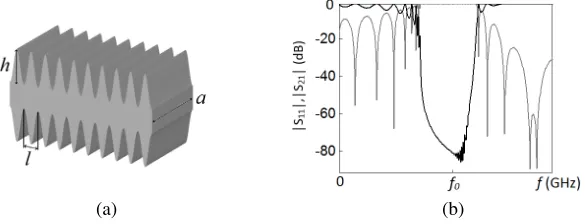
The periodic structure for rectangular waveguide technology employed as a starting point is depicted in Fig. 1. Its unit cells follow a sinusoidal profile, and their resonant behavior will be exploited. When operating in resonance, the stopband frequency is fixed by the height of the unit cells,h, in contrast with the more common case of Bragg operation, where the frequency is fixed by the period, l. Specifically, in order to reject a frequency band aroundf0, exploiting the resonant behavior,h can be calculated for
our periodic structure as:
h≈ λg
4 =
π
2
2πf
0
c 2
−πa2
(1)
where c is the speed of light in vacuum and a the width of the rectangular waveguide [11]. Indeed, inspecting Eq. (1), it can be concluded that the period of the structure,l, has no influence on the value of the rejected frequency, f0, for resonant operation, allowing us to include a large number of unit cells
(with smalll) to achieve high attenuation levels with compact devices.
(a) (b)
Figure 1. Resonant periodic structure: (a) sketch with its main design parameters and (b) frequency response of the structure with 10 unit cells: |S11|in gray line and|S21|in black line.
2.2. Tapering the Height of the Unit Cells: Low-Pass Response
f2, and the bandwidth of the upper stopband, between the frequenciesfmin,H and fmax,H (see Fig. 2).
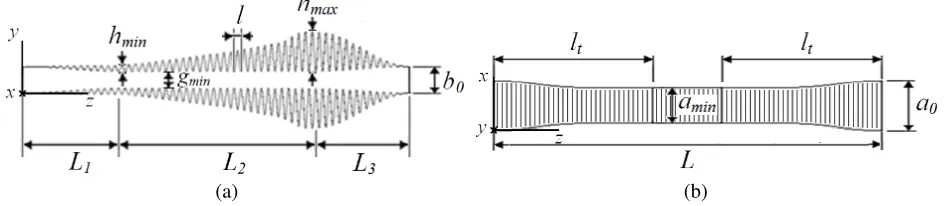
Specifically, a tapered quasi-periodic structure of resonant unit cells with sinusoidal profile and different heights will be defined (see Fig. 3(a)), giving rise to three different sections: L2, which mainly determines
the rejection from fmin,H up tofmax,H, andL1−L3, which mainly determine the passband return loss
level. The minimumEplane mechanical gap,gmin, inL2, can be fixed as large as required, since it is not
a design parameter, and the heights of the highest (hmax) and shortest (hmin) unit cells can be estimated
following (1) to reject the lowest (fmin,H) and highest (fmax,H) frequencies of the upper rejected band,
respectively. Between hmaxand hmin, several unit cells with intermediate heights are used to reject the
intermediate frequencies. L1 and L3 consist also of several tapered unit cells to obtain the required
passband return loss level and achieve height,b0, of the standard waveguide port used. If the number of
unit cells in sectionsL1 andL3is increased, the matching of the passband is improved (higher passband
return loss). In the same way, if the number of unit cells in L2 is made larger, the attenuation in the
upper stopband increases.
Figure 2. Frequency response and specifications for the quasi-periodic structure with band-pass behavior: |S11|in gray line and |S21| in black line.
(a) (b)
Figure 3. Resonant quasi-periodic structure: (a) cross-section showing unit cell height tapering and (b) cross-section showing unit cell width tapering.
2.3. Tapering the Width of the Unit Cells: High-Pass Response
A high-pass frequency response is obtained by tapering the width of the unit cells as in Fig. 3(b). The minimum width, amin, determines the cutoff frequency in the waveguide, allowing propagation
above this frequency and rejecting below it, and thus achieving the high-pass frequency response. The transition between the rectangular waveguide port,a0, and amin contributes to the value of the overall
return loss for the frequencies above the cutoff and determines the slope between the passband and the lower rejected band, i.e., between fmax,L and f1 (see Fig. 2). A width variation along the propagation
return loss for all frequencies beyond the cutoff. Therefore, a(z) can be expressed as:
a(z) = λp
1−1−λ2
pa20
·
1−(λp/amin)2
1−(λp/a0)2
cosnπ2·z
lt
(2)
where lt is the length of the transition, and n and λp are fixed to 3 and 0.9975·amin, respectively, to
achieve the best high-pass performance [12]. Moreover, a0 is determined by the operating frequency
band of the waveguide port, whileaminis fixed taking into account the lowest frequency of the passband,
f1,amin ≈c/2f1. The return loss and slope of the high-pass structure are also determined by the length
of the transition. The longer lt, larger return loss and steeper slope will be achieved.
Since the low-pass behavior of the quasi-periodic structure is mainly determined by the tapering of the height (neither the width,a, nor the length,l) of the unit cells, only the height of the unit cells whose width has been noticeably reduced must be slightly modified after applying width variation to the quasi-periodic structure to achieve the band-pass frequency behavior.
3. DESIGN EXAMPLES. SIMULATION AND MEASUREMENT RESULTS
Following the design procedure explained in the previous section, it is possible to obtain quasi-periodic structures with wide stopbands and very different passband bandwidths, i.e., narrow or wide passbands can be addressed, making these structures of high interest and usefulness. We will firstly discuss the achievable passband bandwidths, showing three examples, and afterwards, we will focus on the simulation and measurement results of one of these examples to prove the performance of the novel quasi-periodic structures proposed.
3.1. Discussion on the Passband Bandwidth of the Quasi-Periodic Structure
Advanced synthesis techniques, such as the one proposed in [14], are required to achieve band-pass filters with a wide passband in rectangular waveguide technology. Interestingly, because the method proposed in this paper is based on the combination of a high-pass and a low-pass response, a large variety of bandwidths can be now easily addressed, even very large ones. In order to prove it, three quasi-periodic
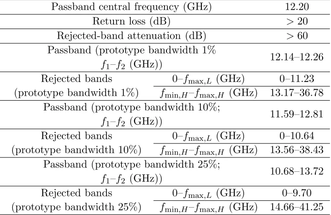
Table 1. Frequency specifications for the quasi-periodic structures (WR75 ports).
Passband central frequency (GHz) 12.20
Return loss (dB) >20
Rejected-band attenuation (dB) >60
Passband (prototype bandwidth 1% f1–f2 (GHz))
12.14–12.26
Rejected bands (prototype bandwidth 1%)
0–fmax,L (GHz) 0–11.23
fmin,H–fmax,H (GHz) 13.17–36.78
Passband (prototype bandwidth 10%; f1–f2 (GHz))
11.59–12.81
Rejected bands (prototype bandwidth 10%)
0–fmax,L (GHz) 0–10.64
fmin,H–fmax,H (GHz) 13.56–38.43
Passband (prototype bandwidth 25%; f1–f2 (GHz))
10.68–13.72
Rejected bands (prototype bandwidth 25%)
0–fmax,L (GHz) 0–9.70
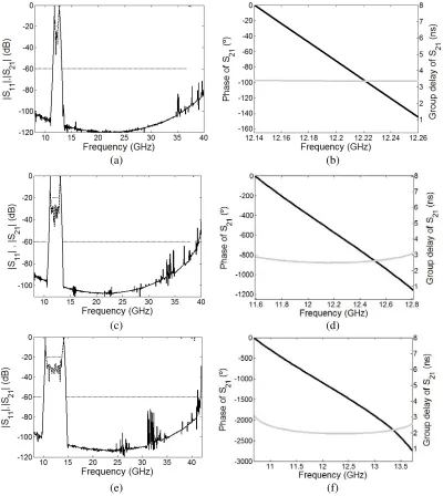
structures have been designed with a large minimum mechanical gap and passband bandwidths equal to 1%, 10%, and 25%, respectively. They present a central passband frequency at 12.2 GHz and a wide upper rejected band up to the third harmonic. The full specification set for the structures is shown in Table 1. In Fig. 4, the simulated frequency responses (obtained with CST Microwave Studio) of the three devices are depicted, showing that these quasi-periodic structures can be employed to fulfil very different passband specifications with a very wide rejected band. In addition to the magnitudes of the S11 and S21 parameters, the relevant phase and group delay of these structures, i.e., the phase and
group delay of the S21 parameter in the passband, are also included in Fig. 4. It is worth noting that
the group delays obtained are approximately flat and, hence, the phase distortion for the propagating signal is negligible.
(a) (b)
(c) (d)
(e) (f)
Figure 4. Simulated frequency response of the novel quasi-periodic structures with band-pass behavior and bandwidth equal to (a) 1%, (c) 10%, and (e) 25%: |S11| in dashed line and |S21| in solid line.
Frequency specifications for |S11|and |S21|are also given in dotted line. Phase (black line) and group
3.2. Measurement Results
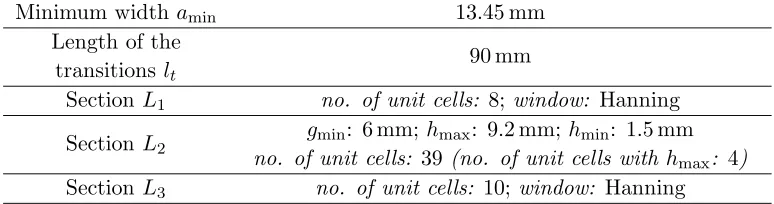
In order to validate the simulated frequency responses obtained in the previous Subsection, a prototype will be fabricated and measured. Specifically, we will focus on the quasi-periodic structure with passband bandwidth equal to 10%. Following the design method explained in Section 2, the final device presents a minimum width amin = 13.45 mm (f1 = 11.59 GHz) and a length of the transitions lt = 90 mm, to
achieve the required rejected band located below the passband (fmax,L = 10.64 GHz). The maximum
and minimum heights of the unit cells are hmax= 9.2 mm and hmin = 1.5 mm, to achieve the required
rejected band between fmin,H = 13.56 GHz andfmax,H = 38.43 GHz, respectively. The number of unit
cells in each section, along with other parameters of the quasi-periodic structure, are shown in Table 2. The minimum mechanical gap of the structure is as large asgmin = 6 mm, which will provide the device
with a high power-handling capability.
A prototype is fabricated in copper by electroforming (see Fig. 5), and the measurements are performed with an Agilent 8722 VNA. Proper waveguide-to-coaxial transitions, calibration kits, and nonlinear tapers are used to measure the frequency response of the device. The measurements, depicted in Fig. 6, confirm the excellent results obtained in simulation, achieving return loss better than 20 dB in the passband and a high attenuation in the lower and upper rejected bands.
Table 2. Dimensions of the quasi-periodic structure prototype (WR75 ports: a0 = 19.05 mm,
b0 = 9.525 mm).
Minimum widthamin 13.45 mm
Length of the
transitions lt 90 mm
Section L1 no. of unit cells: 8;window: Hanning
Section L2
gmin: 6 mm;hmax: 9.2 mm;hmin: 1.5 mm
no. of unit cells: 39(no. of unit cells with hmax: 4)
Section L3 no. of unit cells: 10; window: Hanning
Length of each unit cell,l: 3.8 mm; total device length,L: 216 mm.
Figure 5. Photograph of the fabricated quasi-periodic structure in rectangular waveguide technology.
10 15 20 25 30 35 40
-100 -80 -60 -40 -20 0
Frequency (GHz)
|S
11
| ,
|S
21
| (
d
B
)
Figure 6. Measurements of the fabricated quasi-periodic structure with band-pass behavior (10% bandwidth): |S11|in dashed line and|S21|in solid
line. Frequency specifications for |S11| and |S21|
4. CONCLUSION
In this paper, a novel quasi-periodic structure with band-pass behavior is proposed in rectangular waveguide technology. In order to achieve the band-pass behavior, a combination of low-pass and a high-pass response is performed. The low-pass response is obtained by tapering a periodic structure which consists of resonant sinusoidal unit cells. The height of the unit cells is tapered to obtain a wide rejected band and required return loss in the passband, while the small period of the unit cells is kept constant. Moreover, the high-pass behavior is achieved by means of an appropriate tapering of the unit cells width. The resulting quasi-periodic structures can achieve a large variety of passband bandwidths, even very large ones, and show good matching and a wide rejected band, up to the third harmonic, much wider than that achievable by means of classical waveguide band-pass filters. Moreover, the structures feature a large minimum mechanical gap that makes their use possible in high-power applications. The implementation of waveguide band-pass filters and diplexers with demanding specifications (wide rejected band, wide passband and/or high power operation) are very promising applications for the novel quasi-periodic structures proposed.
ACKNOWLEDGMENT
This work was supported by MINECO (Spain) under projects 51902-C2-2-R and TEC2014-55735-C3-R.
REFERENCES
1. Oliner, A. and W. Rotman, “Periodic structures in through waveguides,” IRE Transactions on Microwave Theory and Techniques, Vol. 7, No. 1, 134–142, 1959.
2. Marini, S., P. Soto, A. Cover, B. Gimeno, and V. Boria, “Practical design of filters using EBG waveguides periodically loaded with metal ridges,”Progress in Electromagnetic Research C, Vol. 63, 13–21, 2016.
3. Cutler, C. C., “Corrugated wave guide devices,” U.S. Patent 2912695, 1959.
4. Azam, G. and H. Leboutet, “Waveguide structure for linear particle accelerators having an undulating configuration,” U.S. Patent 3263116, 1966.
5. Mallick, K. and G. S. Sanyal, “Electromagnetic wave propagation in a rectangular waveguide with sinusoidally varying width,” IEEE Transactions on Microwave Theory and Techniques, Vol. 26, No. 4, 243–249, 1978.
6. Asfar, O. R. and A. H. Nayfeh, “Circular waveguide with sinusoidally perturbed wall,” IEEE Transactions on Microwave Theory and Techniques, Vol. 23, No. 9, 728–734, 1975.
7. Bostr¨om, “Passbands and stopbands for an electromagnetic waveguide with a periodically varying cross section,” IEEE Transactions on Microwave Theory and Techniques, Vol. 31, No. 9, 752–756, 1983.
8. Chong, C. K., D. B. McDermott, M. M. Razeghi, N. C. Luhmann, Jr., J. Pretterebner, D. Wagner, M. Thumm, M. Caplan, and B. Kulke, “Bragg reflectors,” IEEE Transactions on Plasma Science, Vol. 20, No. 3, 393–402, 1992.
9. Kovalev, N. F., I. M. Orlova, and M. I. Petelin, “Wave transformation in a multi-mode waveguide with corrugated walls,”Radiophysics and Quantum Electronics, Vol. 11, 449–450, 1968.
10. Arregui, I. A., A. Lujambio, M. Chudzik, M. A. G. Laso, T. Lopetegi, and M. Sorolla, “Design method for satellite output multiplexer low-pass filters exhibiting spurious-free frequency behavior and high-power operation,” Microwave and Optical Technology Letters, Vol. 52, No. 8, 1724–1728, 2010.
12. Tang, C. C. H., “Nonuniform waveguide high-pass filters with extremely steep cutoff,” IEEE Transactions on Microwave Theory and Techniques, Vol. 12, No. 3, 1964.
13. Hauth, W., R. Keller, and U. Rosenberg, “The corrugated-waveguide band-pass filter - A new type of waveguide filter,” Proceedings of 18th European Microwave Week, 945–949, Stockholm, 1988. 14. Soto, P., E. Tar´ın, V. E. Boria, C. Vicente, J. Gil, and B. Gimeno, “Accurate synthesis and design
of wideband and inhomogeneous inductive waveguide filters,” IEEE Transactions on Microwave Theory and Techniques, Vol. 58, No. 8, 2010.