Scholarship@Western
Scholarship@Western
Electronic Thesis and Dissertation Repository
4-8-2014 12:00 AM
Development of an In-Vitro Passive and Active Motion Simulator
Development of an In-Vitro Passive and Active Motion Simulator
for the Investigation of Shoulder Function and Kinematics
for the Investigation of Shoulder Function and Kinematics
Joshua W. Giles
The University of Western Ontario Supervisor
Prof. James A. Johnson
The University of Western Ontario
Graduate Program in Biomedical Engineering
A thesis submitted in partial fulfillment of the requirements for the degree in Doctor of Philosophy
© Joshua W. Giles 2014
Follow this and additional works at: https://ir.lib.uwo.ca/etd Part of the Biomechanics and Biotransport Commons
Recommended Citation Recommended Citation
Giles, Joshua W., "Development of an In-Vitro Passive and Active Motion Simulator for the Investigation of Shoulder Function and Kinematics" (2014). Electronic Thesis and Dissertation Repository. 1950.
https://ir.lib.uwo.ca/etd/1950
This Dissertation/Thesis is brought to you for free and open access by Scholarship@Western. It has been accepted for inclusion in Electronic Thesis and Dissertation Repository by an authorized administrator of
DEVELOPMENT OF AN IN-VITRO PASSIVE & ACTIVE MOTION SIMULATOR FOR THE INVESTIGATION OF SHOULDER FUNCTION AND KINEMATICS
(Thesis format: Integrated Article)
by
Joshua William Giles
Graduate Program in Biomedical Engineering
A thesis submitted in partial fulfillment of the requirements for the degree of
Doctor of Philosophy
The School of Graduate and Postdoctoral Studies The University of Western Ontario
London, Ontario, Canada
Abstract
Injuries and degenerative diseases of the shoulder are common and may relate to the joint’s complex biomechanics, which rely primarily on soft tissues to achieve stability. Despite the prevalence of these disorders, there is little information about their effects on the biomechanics of the shoulder, and a lack of evidence with which to guide clinical
practice. Insight into these disorders and their treatments can be gained through in-vitro
biomechanical experiments where the achieved physiologic accuracy and repeatability directly influence their efficacy and impact.
This work’s rationale was that developing a simulator with greater physiologic accuracy and testing capabilities would improve the quantification of biomechanical parameters. This dissertation describes the development and validation of a simulator capable of performing passive assessments, which use experimenter manipulation, and active assessments – produced through muscle loading. Respectively, these allow the assessment of functional parameters such as stability, and kinematic/kinetic parameters including joint loading.
The passive functionality enables specimen motion to be precisely controlled through independent manipulation of each rotational degree of freedom (DOF). Compared to unassisted manipulation, the system improved accuracy and repeatability of positioning the specimen (by 205% & 163%, respectively), decreased variation in DOF that are to remain constant (by 6.8°), and improved achievement of predefined endpoints (by 21%). Additionally, implementing a scapular rotation mechanism improved the physiologic accuracy of simulation. This enabled the clarification of the effect of secondary musculature on shoulder function, and the comparison of two competing clinical reconstructive procedures for shoulder instability.
This was the first shoulder system to use real time kinematic feedback and PID control to produce active motion, which achieved unmatched accuracy (<1°) and repeatability (0.3°). Additionally, the controller increased the physiologic accuracy of motion simulation, compared to previous systems. Using these developments and custom
designed adjustable instrumented Reverse Total Shoulder Arthroplasty implants, the effects of implant parameters on muscle loading and joint load were assessed throughout active motion. This study provided new insights, unattainable without this research’s developments.
These developments can be a powerful tool for increasing our understanding of the shoulder and also to provide information which can assist surgeons and improve patient outcomes.
Keywords
Shoulder motion, in-vitro simulation, biomechanics, passive simulation, active
simulation.
Co-Authorship Statement
Chapter 1: Josh Giles – sole author
Chapter 2: Josh Giles – developed testing systems, study design, data collection, statistical analysis, wrote manuscript
Irfan Abdulla – data collection
James Johnson – study design, reviewed manuscript
George Athwal – study design, data collection, reviewed manuscript Chapter 3: Josh Giles – study design, data collection, statistical analysis, wrote
manuscript
Harm Boons – study design, specimen preparation, data collection, reviewed manuscript
Louis Ferreira – study design, reviewed manuscript
George Athwal – study design, data collection, reviewed manuscript James Johnson – study design, reviewed manuscript
Chapter 4: Josh Giles – study design, data collection, statistical analysis, wrote manuscript
Ryan Degen – study design, specimen preparation, data collection, reviewed manuscript
George Athwal – posed clinical question, study design, reviewed manuscript James Johnson – study design, reviewed manuscript
Chapter 5: Josh Giles – developed controller, study design, data collection, statistical analysis, wrote manuscript
Louis Ferreira – technical advice, study design, reviewed manuscript George Athwal – study design, data collection, reviewed manuscript James Johnson – study design, reviewed manuscript
Chapter 6: Josh Giles – developed implant system, study design, data collection, statistical analysis, wrote manuscript
Dan Langohr – developed implant system, study design, data collection George Athwal – study design, specimen preparation, reviewed manuscript James Johnson – study design, reviewed manuscript
Chapter 7: Josh Giles – sole author
Acknowledgments
I would like to begin by thanking my supervisors, Dr James Johnson and Dr George Athwal, for their continual support and advice throughout my research and training. I cannot begin to think where I would be without their help and without the lessons one can only learn from supervisors with such passion and expertise. Dr Johnson, thank you for
plucking me out of your 2nd year Mechanics of Materials class and giving me the
opportunity to experience research in a field that I scarcely knew existed or thought would interest me! From that time on you have always encouraged me to do the best research I can and you have always been available at just the right time to answer my questions and address my concerns. Dr Athwal, your fervor for research and your foresight in seeing how the work of this thesis could address important clinical questions allowed us to establish a line of research that I am so proud of! Thank you for always making our research a priority despite your myriad of other commitments. I feel so lucky to have worked with you over these past 5 years. I would also like to thank Dr. Graham King. Although you were not a direct supervisor of mine, you are the clinical forefather of this lab and always pushed me to achieve more with my research with your not so subtle questions, like ‘got that scapula moving yet’? I can happily report that I did finally get it moving…and it was veiled encouragement like yours that helped make the shoulder simulator be all it could be during my five years.
To Louis, I always appreciated your general and technical advice and how you always made time to give it. I am not sure where I or my research would be without the knowledge you gave me. You allowed me to avoid the pitfalls you and your elbow simulator predecessors encountered, and were always there with a good idea when a problem arose during testing. For that, I cannot thank you enough.
To all of the students, surgeons, staff, and volunteers at the HULC Bioengineer lab that I have worked with over the years, thank you for always striving to produce research of such a high quality. Working with each of you on your research and your help with mine has made the past seven years unbelievably rewarding and educational. I would specifically like to thank Emily for being my closest friend in the lab throughout these years. I always enjoyed working with you, especially our LabView coding sessions,
because no matter how long it sometimes took, you always stuck it out with me! Hannah and Simon, you were great labmates and I enjoyed hanging out with you day in and day out, especially in the inevitable times when it seemed like the research just wasn’t progressing. Ryan, thank you for always offering your help, especially during my long days of controller development. It never ceased to amaze me how you could always approach a problem from a different angle and produce an innovative solution! Dan, we have only started to work together more recently, but your seemingly unending energy and drive has made this period one of my most productive. I cannot wait to see the impact our studies can have! To all of the surgical residents and fellows I have worked with, without you, my research wouldn’t have been nearly so clinically relevant.
I would also like to thank Brooke Thompson for creating the wonderful anatomical illustrations used throughout my first chapter. They have given this work a good foundation and great style.
To my family, thank you for all of your support and your interest in my work over the years. Mom and Dad, thank you for your continual help and encouragement throughout my schooling and in all parts of my life. I would not be where I am today without your help, especially in my early education, and wouldn’t be on the verge of receiving my Doctorate.
Finally, and most importantly, to my better half and long suffering editor, Jasmine, you have been by my side since before I started in the lab seven years ago. In that time many things have changed, I have flown on my first plane (transpacific no less), we have moved in together, bought a house (sold a house), and gotten married, but the one constant was that you were always there to listen, encourage, and help me with my research. I love you so much and will never be able to repay you for your patience, effort, and investment of time but I can promise that there are fewer work nights ahead and I know that we will fill them with conversation and new experiences as we always have!
Table of Contents
Abstract ... ii
Co-Authorship Statement ... iv
Acknowledgments ... v
Table of Contents ... vii
List of Tables ... xiii
List of Figures ... xiv
List of Equations ... xviii
List of Appendices ... xix
Abbreviations, Symbols And Nomenclature ... xx
CHAPTER 1 – Introduction ... 1
1.1 The Shoulder Complex ... 1
1.2 Anatomy ... 1
1.2.1 Osseous Constructs ... 2
1.2.2 Joint Capsule and Ligaments ... 11
1.2.3 Muscles ... 13
1.3 Function ... 20
1.4 Humerothoracic Motions ... 20
1.5 Joint Stabilizers ... 25
1.5.1 Bony Anatomy ... 26
1.5.2 Soft Tissue Passive Stabilizers ... 27
1.5.3 Soft Tissue Active Stabilizers – Muscles ... 28
1.6 Techniques in the Study of Glenohumeral Joint Biomechanics ... 31
1.6.1 The Technologies of In-Vitro Biomechanical Research ... 34
1.6.2 The Processes of In-Vitro Biomechanical Research ... 39
1.7 In-Vitro Shoulder Simulators ... 46
1.7.1 Static Shoulder Simulators ... 47
1.7.2 Dynamic Shoulder Simulators ... 47
1.8 Rationale ... 50
1.9 Objectives and Hypotheses ... 51
1.10Thesis Overview ... 53
1.11References ... 54
CHAPTER 2 – Development, Augmentation, and Validation of a Static and Passive Glenohumeral-Scapulothoracic Shoulder Simulator ... 67
2.1 Introduction ... 68
2.2 Methods ... 70
2.2.1 Design Requirements & Constraints ... 70
2.2.2 Humeral Positioning Apparatus ... 70
2.2.3 Scapular Rotation Apparatus ... 78
2.2.4 Muscle Loading & Guide System ... 79
2.2.5 Multi-Articular Muscle Loading ... 84
2.2.6 Integrated Load Sensing and Spatial Tracking Device ... 85
2.2.7 Validation ... 87
2.3 Results ... 89
2.3.1 Humeral Guide ... 89
2.3.2 Muscle Loading & Guide System ... 90
2.3.4 Integrated Load Sensing and Spatial Tracking Device ... 92
2.4 Discussion ... 92
2.5 References ... 98
CHAPTER 3 – The Effect of the Conjoined Tendon of the Short Head of the Biceps and Coracobrachialis on Shoulder Stability & Kinematics
during In-Vitro Simulation ... 100
3.1 Introduction ... 101
3.2 Methods ... 101
3.2.1 Simulator Configuration ... 101
3.2.2 Stiffness & Kinematics ... 104
3.2.3 Outcome Variables & Statistical Methods ... 108
3.3 Results ... 108
3.4 Discussion ... 111
3.5 References ... 115
CHAPTER 4 – The Bristow-Latarjet: Why These Techniques Should Not Be Considered Synonymous... 118
4.1 Introduction ... 119
4.2 Materials & Methods ... 121
4.2.1 Specimen Preparation and Shoulder Simulator ... 121
4.2.2 Experimental Testing Protocol ... 122
4.2.3 Stability and Range of Motion ... 125
4.2.4 Outcome Variables & Statistical Analyses ... 126
4.3 Results ... 127
4.3.1 Joint Stiffness and Stability ... 127
4.3.2 Range of Motion ... 129
4.4 Discussion ... 132
4.5 References ... 136
CHAPTER 5 – Development and Validation of a Multi-PID Muscle Loading Driven In-Vitro Active Motion Shoulder Simulator ... 140
5.1 Introduction ... 141
5.2 Materials & Methods ... 142
5.2.1 Specimen Preparation ... 142
5.2.2 Glenohumeral Joint Control System ... 145
5.2.3 Scapular Orientation Control ... 150
5.2.4 Validation Outcome Variables ... 153
5.3 Results ... 154
5.3.1 Performance ... 154
5.3.2 Control System Characterization ... 155
5.4 Discussion ... 159
5.5 Nomenclature ... 166
5.6 References ... 167
CHAPTER 6 – The Influence of Reverse Total Shoulder Arthroplasty Implant Geometric Variables on Muscle Activation, Joint Load and Shoulder Function ... 170
6.1 Introduction ... 171
6.2 Materials & Methods ... 172
6.2.1 Custom Adjustable & Instrumented RTSA System ... 172
6.2.2 Specimen Preparation ... 178
6.2.3 Simulator Testing Apparatus ... 181
6.2.4 Experimental Testing Protocol ... 182
6.2.5 Outcome Variables & Statistical Analyses ... 183
6.3 Results ... 187
6.3.1 Active IR & ER ROM ... 187
6.3.2 Joint Load ... 187
6.3.3 Total Deltoid Load ... 191
6.3.4 Joint Load Angle ... 191
6.4 Discussion ... 194
6.4.1 Active IR & ER ROM ... 194
6.4.2 Joint Load ... 195
6.4.3 Total Deltoid Load ... 196
6.4.4 Joint Load Angle ... 197
6.4.5 Limitations and Strengths ... 197
6.4.6 Conclusion ... 198
6.5 References ... 201
CHAPTER 7 – General Discussion and Conclusions ... 205
7.1 Summary ... 205
7.2 Strength and Limitations ... 209
7.3 Current and Future Directions ... 210
7.4 Significance ... 213
7.5 References ... 215
Appendix A – Index of Anatomical & Research Terminology ... 216
Appendix B – Inverse Kinematic Calculations for the Scapular Rotation Motor and Linkage System ... 226
Appendix C – Implementation of a Geometric Motion-Decomposition Technique for the Elimination of Gimbal Lock Artifacts in Real-Time Active Motion Kinematic Data ... 229
C.1 Introduction ... 229
C.2 Materials and Methods ... 230
C.3 Results ... 234
C.5 Discussion ... 237
C.6 References ... 239
Appendix D – Full Range of Adjustability of Custom Modular Reverse Total Shoulder Arthroplasty Components... 240
Appendix E – Evaluation of the Accuracy of Transformed Six DOF Load
Measurements Made Using a Glenosphere Embedded Load Cell ... 245
E.1 Introduction ... 245
E.2 Methods ... 245
E.3 Results ... 249
E.4 Discussion ... 251
E.5 References ... 255
Curriculum Vitae ... 256
List of Tables
Table 4.1: Incidents of Glenohumeral Dislocation for Two Stability Tests ... 130
Table 5.1: Muscle Loading Ratios. ... 146
Table 5.2: PID Control Parameters. ... 151
Table 6.1: Tested levels of RTSA implant parameters. ... 184
Table 6.2: Muscle loading ratios used to achieve active internal and external rotation. ... 184
Table 6.3: Summary of implant parameters with significant main effects for active motion outcome variables. ... 189
List of Figures
Figure 1.1: The shoulder complex ... 3
Figure 1.2: The osseous anatomy of the scapula and clavicle. ... 4
Figure 1.3: Soft tissue structures of scapula viewed from lateral. ... 6
Figure 1.4: The osseous anatomy of the humerus. ... 8
Figure 1.5: Anterolateral view of the joint capsule and ligaments. ... 12
Figure 1.6: The muscular origins and insertions on the scapula. ... 14
Figure 1.7: The muscular origins and insertions on the humerus. ... 15
Figure 1.8: The muscles of the shoulder complex. ... 16
Figure 1.9: Humeral rotations used to describe motion. ... 21
Figure 1.10: Scapular rotations used to describe motion. ... 22
Figure 1.11: Six DOF load cell coordinate system. ... 40
Figure 1.12: Local Bone Fixed coordinate systems in the shoulder complex. ... 42
Figure 1.13: Y-X-Y Euler angle decomposition method. ... 44
Figure 2.1: The humeral guide arc. ... 72
Figure 2.2: Spherical bearing used to mate humeral rod to guide arc. ... 73
Figure 2.3: Humeral guide arc mounted to existing simulator base ... 75
Figure 2.4: Simulator with humeral guide arc and scapular potting and rotation mechanism ... 76
Figure 2.5: The humeral guide arc viewed from above ... 77
Figure 2.6: The scapular potting and rotation mechanism ... 80
Figure 2.7: The two muscle cable guides. ... 82
Figure 2.8: The entire shoulder simulator with specimen mounted. ... 83
Figure 2.9: The instrumented intramedullary humeral rod. ... 86
Figure 2.10: Variation in abduction. ... 91
Figure 2.11: Load loss in actuator and guide system. ... 93
Figure 2.12: Ability to meet a predefined torque value. ... 93
Figure 3.1: Rendering ofthe in-vitro shoulder simulator. ... 103
Figure 3.2: Schematic of shoulder specimen testing configuration. ... 105
Figure 3.3: Sample load versus displacement profile for drawer test. ... 106
Figure 3.4: Joint stiffness for varying SH&C load. ... 109
Figure 3.5: Joint stiffness for varying SH&C load and joint configuration. ... 109
Figure 3.6: Ranges of motion for varying SH&C load. ... 110
Figure 4.1: Renderings of the Bristow (A) and Latarjet (B) coracoid transfers. ... 120
Figure 4.2: Renderings of the scapula showing the three levels of bony deficiency. ... 123
Figure 4.3: Adducted anterior glenohumeral joint stiffness. ... 128
Figure 4.4: Abducted anterior glenohumeral joint stiffness. ... 128
Figure 4.5: Glenohumeral joint ranges of motion. ... 131
Figure 5.1: Shoulder Active Motion Simulator. ... 144
Figure 5.2: Block Diagram of Shoulder Active Motion Control System. ... 148
Figure 5.3: Example Muscle Loads Produced by Motion Controller. ... 152
Figure 5.4: Abduction & Horizontal Extension Profiling Accuracy and Repeatability. ... 156
Figure 5.5: Effect of Variations in Specimen’s Size-to-Mass Ratio. ... 157
Figure 5.6: Effect of Varying Proportional and Integral Gains on Controller Characteristics. ... 158
Figure 5.7: Simulator’s Response to Scapular Disturbance. ... 160
Figure 6.1: Custom modular Reverse Total Shoulder Arthroplasty implants... 174
Figure 6.2: Custom modular humeral implant of our Reverse Total Shoulder Arthroplasty. ... 175
Figure 6.3: Custom modular scapular implant of our Reverse Total Shoulder Arthroplasty. ... 177
Figure 6.4: Photograph of implanted humeral component. ... 179
Figure 6.5: Photographs of glenosphere implantation. ... 180
Figure 6.6: Definition of loading angle convention. ... 186
Figure 6.7: Implant variables with main effects on IR and ER ROM. ... 188
Figure 6.8: Implant variables whose effects on joint load varied across abduction. ... 190
Figure 6.9: Total deltoid load across abduction. ... 192
Figure 6.10: Total deltoid load interaction between humeral and glenosphere offset. ... 192
Figure 6.11: Joint load angle across abduction. ... 193
Figure B.1: Computer rendering of scapular rotation linkage. ... 226
Figure B.2: Hand written solution for inverse kinematics of scapular rotation
linkage. ... 228
Figure C.1: Shoulder phantom used in assessment of kinematic analysis
techniques. ... 233
Figure C.2: Flexion-extension motion with arm held in 90° of glenohumeral
abduction. ... 235
Figure C.3: Internal-external rotation motion with arm held in 0° of glenohumeral
abduction. ... 235
Figure C.4: Abduction motion in scapular plane. Note that the plane of abduction and axial rotation DOF were held constant. ... 236
Figure D.1: Glenosphere sizes for custom modular implant. ... 240
Figure D.2: Available humeral polyethylene cup retention levels. ... 241
Figure D.3: Adjustability of humeral polyethylene cup thickness, and humeral
lateralization. ... 242
Figure D.4: Adjustability of humeral retroversion, and humeral head-neck angle. ... 243
Figure D.5: Adjustability of glenosphere size, and glenosphere lateral and inferior offset. ... 244
Figure E.1: Load transformation validation testing setup. ... 247
Figure E.2: Force difference between transformed primary readings and secondary load cell measurements. ... 250
Figure E.3: Moment difference between transformed primary readings and secondary load cell measurements. ... 250
Figure E.4: Differences between resultant forces measured by each load cell. ... 253
List of Equations
Equation 1.1: Transformation matrix definition and chain multiplication rule. ... 41
Equation 5.1: Ziegler-Nichols equations for determination of Integral Time PID
parameter initial guess. ... 150
Eq. E.1: Coordinate system transformation of measured forces using spatial math. ... 246
Eq. E.2: Coordinate system transformation of measured moments using spatial math ... 246
List of Appendices
Appendix A: Index of Anatomical & Research Terminology ... 216 Appendix B: Inverse Kinematic Calculations for the Linkage and Motor System ... 226 Appendix C: Implementation of a Geometric Motion-Decomposition Technique
for the Elimination of Gimbal Lock Artifacts in Real-Time Active Motion
Kinematic Data ... 229 Appendix D: Full Range of Adjustability of Custom Modular Reverse Total
Shoulder Arthroplasty Components ... 240 Appendix E: Evaluation of the Accuracy of Transformed Six DOF Load
Measurements Made Using a Glenosphere Embedded Load Cell... 245
Abbreviations, Symbols And Nomenclature
Add ... Adduction Abd ... Abduction ANOVA ... Analysis of Variance statistical method ASD ... Average Standard Deviation BMI ... Body Mass Index PID ... Proportional Integral Derivative CS ... Coordinate System DC ... Direct Electrical Current DOF ... Degree(s)-Of-Freedom ER ... External Rotation Fx,y,z ... Force along the x, y, or z axis GSA ... Dr George S. Athwal GMD ... Geometric Motion Decomposition HH ... Humeral Head HULC ... Hand and Upper Limb Centre INA ... Dr. Irfan N. Abdullah IE ... Internal-External IR ... Internal Rotation ISB ... International Society of Biomechanics JCS ... Joint Coordinate System
Ku ... Proportional gain causing oscillation in a proportional only controller
Kp ... Proportional gain in proportional only controller causing a Quarter Amplitude Decay Response
Mx,y,z ... Moment about the x, y, or z axis MRI ... Magnetic Resonance Imaging N ... Force in Newtons Nm ... Moment in Newton Meters NR ... Neutral IE Rotation N/mm ... Stiffness in Newtons per Millimeter p ... Statistical significance p-value
pCSA ... physiologic Cross Sectional Area 𝑝
𝐵𝑥
𝐴 ... position element of CS A wrt x axis of CS B 𝑃�
𝐵
𝐴 ... position vector of point A wrt CS B 𝑟𝐴𝑥
𝐵𝑥 ... rotation element of CS A wrt CS B – example shown is for x axis in each CS
ROM ... Range Of Motion RM ... Repeated Measures RMSE ... Root Mean Squared Error RSA ... Radio-Stereometric Analysis RTSA ... Reverse Total Shoulder Arthroplasty SD ... Standard Deviation SDA ... Screw Displacement Axis SH&C ... Short Head of the Biceps & Coracobrachialis
𝑇 𝐴
𝐵 ... Transformation matrix of A wrt CS B
Td ... Initial derivative time value
Ti ... Initial integral time value
Tu ... Estimated oscillation period wrt ... with respect to
𝑋� 𝐴 𝐵 , 𝑌� 𝐴 𝐵 , 𝑍̂ 𝐴
𝐵 ... Axes column vectors of CS A wrt CS B
%BW ... Percent Body Weight Δθ ... Change in angle Theta (θ) ^ ... over a vector label denotes a unit vector ° ... degrees (unit of rotation) ± ... plus or minus; prefixes magnitude of one standard deviation Δ ... (delta) indicating change → ... between items; denotes sequence of execution in direction of arrow
CHAPTER 1 – Introduction
1
-OVERVIEW
This chapter explores the gross anatomy of the shoulder joint complex, its stabilizing mechanisms, and its physiologic function. A review is also provided of previous and current testing methodologies used for the assessment of static, passive, and active shoulder biomechanics, and of the technologies and techniques underlying this research. In concluding, the chapter addresses the biomechanical and clinical questions to be addressed, and the hypotheses of this work.
1.1 The Shoulder Complex
The “shoulder joint,” as it is commonly (mis)termed, is in fact composed of three bones, three joints, a gliding articulation, and an array of muscles, tendons and ligaments all functioning together to produce arm motion with the goal of positioning the hand in space (Jobe et al., 2009). The combined effect of these components is a joint complex capable of achieving the largest range of motion, greater than a hemisphere, of any in the human body (Culham & Peat, 1993; Peat, 1986). However, optimal joint function and kinematics are readily disturbed if any of these components are affected by injury or disease (Neer, 1990).
1.2 Anatomy
1.2.1
Osseous Constructs
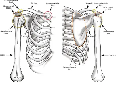
The shoulder complex is composed of three bones – the clavicle, the scapula, and the humerus, which articulate with each other and the torso through three joints – the sternoclavicular joint, the acromioclavicular joint, and the glenohumeral joint (Figure 1.1). Additionally, the complex includes the scapulothoracic joint, a gliding articulation between the scapula and the chest wall, and the subacromial articulation, composed of the scapula and humerus (Culham & Peat, 1993).
1.2.1.1 Bones
The scapula is a triangular bone which forms the primary link between the upper limb and the axial skeleton (Figure 1.2), and serves as the main attachment site for many muscles involved in shoulder motion. These muscles originate on the torso and insert on the scapula to cause scapular motion, or originate on the scapular body and insert on one of the bones of arm to produce arm motion. The scapula’s primary role is two-fold: to support the mass of the upper limb during motion, and to expand the hand’s functional range of motion by acting as a movable platform for the arm (Rockwood, 2009). Despite its function, the scapula is a very thin bone, to the point of translucency in many cases, and requires support from attaching muscles and articulating structures to prevent it from buckling (von Schroeder, Kuiper, & Botte, 2001).
Figure 1.1: The shoulder complex
Figure 1.2: The osseous anatomy of the scapula and clavicle.
It functions as an attachment for the deltoid and trapezius muscles and increases the
middle deltoid’s moment arm (i.e. mechanical advantage) (Goss & Owens, 2009; Jobe et
al., 2009). It is also the attachment site for one end of the coracoacromial ligament whose other end attaches to the coracoid process. The coracoid process is also the insertion site of the pectoralis minor muscle which runs from the torso, as well as the origin site of the conjoint tendon, which crosses the shoulder. O'Brien, Voos, Neviaser, and Drakos (2009) suggested that the coracoid may also act as an anterior humeral head stabilizer with the
arm in 90° of abduction.
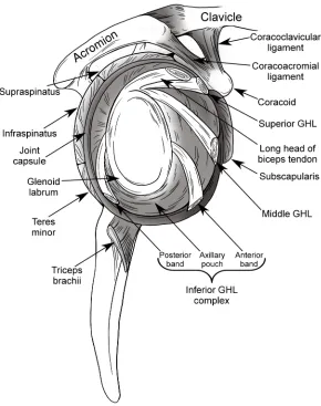
Since the scapula’s role is to function as a platform for arm motion, its most important osseous anatomical feature is the shallow pear-shaped fossa located at the lateral aspect of the scapular body known as the glenoid (Figure 1.3). The glenoid surface is covered in hyaline cartilage, which has been found to have increasing thickness at the periphery in order to deepen the fossa and increase conformity with the head of the humerus (Soslowsky, Flatow, Bigliani, & Mow, 1992). Additionally, the fossa’s depth is further increased by a fibrocartilaginous ring of tissue at the rim of the glenoid termed the glenoid labrum. The labrum also broadens the articular surface, thus increasing the available contact area with the humeral head, and also serves as an attachment site for various glenohumeral ligaments (Culham & Peat, 1993; O'Brien et al., 2009). The advantage of this stabilizing soft tissue structure lies in the increased range of motion it permits compared to a more conforming osseous cup, as with the acetabulum of the hip (Itoi, Morrey, & An, 2009; Moseley & Overgaard, 1962). Glenoid fossa size and orientation has been assessed by a number of groups with significantly variable findings; however, glenoid surface area is generally accepted to be approximately 1/3 that of the
humeral head with the labrum attached and 1/4 without, and is oriented upward by ~5°
and between 7° retroverted and 2° anteverted (Itoi et al., 2009).
Figure 1.3: Soft tissue structures of scapula viewed from lateral.
between the scapula and torso which would be otherwise compromised by scapulothoracic and humerothoracic muscle loading. The clavicle also serves as an attachment site for many muscle groups and influences scapular rotation during arm motion (Ludewig et al., 2009; McClure, Michener, Sennett, & Karduna, 2001; Van der Helm & Pronk, 1995).
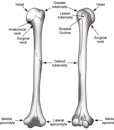
The humerus (Figure 1.4) forms the proximal portion of the upper extremity. Its proximal end terminates as the humeral head, whose articular surface forms a third of a sphere and faces superior, medial, and posterior (O'Brien et al., 2009). The orientation of this articular surface is intended to facilitate load transmission from the arm to the torso while permitting maximum motion and maintaining joint stability (Itoi et al., 2009). As with the glenoid fossa, the humeral articular surface is coated in cartilage to disperse the transmitted load over a larger surface and thus decrease contact stresses on the bone; however, in this case, cartilage thickness is nearly constant (Soslowsky et al., 1992).
The humeral head possesses a number of other important anatomical features including the lesser and greater tuberosities, and bicipital groove. Both the lesser and greater tuberosities originate just lateral to the articular margin of the humeral head, with the lesser tuberosity lying anterolateral and the greater tuberosity lying posterolateral. The lesser tuberosity serves as the insertion site for the subscapularis muscle of the rotator cuff, and the greater tuberosity serves as an attachment for the supraspinatus superiorly, infraspinatus posteriorly, and teres minor posteroinferiorly. The moment which can be applied by the supraspinatus and deltoid muscle groups about the glenohumeral joint is enhanced by the structure of the greater tuberosity which elevates the supraspinatus above
30° of abduction and causes deltoid wrapping below 60° (Ackland, Pak, Richardson, &
Figure 1.4: The osseous anatomy of the humerus.
approximately mid-shaft, and serves as a common insertion for the three subgroups of the deltoid muscle. The medial and lateral epicondyles are located within the elbow anatomy and serve no shoulder function but are an important landmark for physiologically describing shoulder motion.
1.2.1.2 Joints
The joints that form the shoulder complex serve two primary functions: to achieve maximal range of motion and to maintain sufficient stability to prevent dysfunction and/or injury (Jobe et al., 2009).
Veeger, 2000). With this in mind, the glenohumeral joint is thus typically considered a true three rotation ball-in-socket joint (Culham & Peat, 1993; Howell et al., 1988; Poppen & Walker, 1976; Veeger, 2000); however, translations of the humeral head have been shown to be relevant in pathological and reconstructed joint conditions, such as following dislocation (Apreleva et al., 1998; Burkart, Debski, Musahl, & McMahon, 2003; McMahon, Burkart, Musahl, & Debski, 2004).
The acromioclavicular and sternoclavicular joints are the articulations between the lateral clavicle and the acromion on the scapula, and the medial clavicle and the sternum, respectively. Both of these joints are characterized by the fibrocartilaginous coverings on each bone surface and a fibrocartilaginous disc interposed between them (Culham & Peat, 1993; Peat, 1986). Although these joints can be anatomically defined as plane synovial joints, the sternoclavicular joint functions similarly to a ball-in-socket joint, allowing the clavicle to move in a cone of motion which in turn permits scapular elevation and pro-retraction (Culham & Peat, 1993). In contrast, the acromioclavicular joint permits minimal motion typically composed of inferomedial translation during excessive load application. The role of these two joints is to support and stabilize the scapula while transmitting loads axially to the torso (Culham & Peat, 1993).
The subacromial space is formed by the rotator cuff inferiorly, the acromion superiorly, and the coracoid, and coracoacromial ligament anteriorly (Culham & Peat, 1993). This space’s primary role is to aid smooth humeral motion under the acromion, and its anterior structures (coracoid and coracoacromial ligament) act to stabilize the joint superiorly.
1.2.2
Joint Capsule and Ligaments
The joint capsule and ligaments (Figure 1.3 & Figure 1.5) compose the portion of soft tissues in the shoulder complex responsible for providing passive stability as will be discussed in Section 1.5.2.
A joint’s capsule is a thin membrane surrounding the articulating surfaces of a synovial joint that excretes nutrients and lubricating synovial fluid. In the glenohumeral joint, the capsule is relatively loose but becomes tensioned at extreme joint configurations (Peat, 1986). Medially, the glenohumeral joint capsule blends into the glenoid labrum and rim, while, laterally, it attaches to the articular margin of the humeral head.
The joint capsule is reinforced posteriorly by the infraspinatus and teres minor tendons, and anteriorly by both the subscapularis tendon and the glenohumeral ligaments (Clark & Harryman, 1992; Hess, 2000). The morphology of the glenohumeral ligaments varies but they are most commonly characterized as broad thickenings of the capsule superiorly, anteriorly, and inferiorly that may or may not blend into each other (Clark & Harryman, 1992; Neer, 1990). This structure is believed to exist in place of the discrete ligamentous bands seen in other joints as a result of the need to support both tensile and shear loads present in the highly mobile glenohumeral joint (Debski et al. 1999b). Additionally, unlike other ligaments, the glenohumeral ligaments can become taut in the mid-range of motion, typically as a result of internal or external rotation (Burkart & Debski, 2002).
Figure 1.5: Anterolateral view of the joint capsule and ligaments.
posterior band. The former has been found to limit external rotation and anterior translation during abduction while the latter limits internal rotation and posterior translation in abduction (Burkart & Debski, 2002; Culham & Peat, 1993).
The transverse humeral ligament runs from the lesser to the greater tuberosity, thus covering the bicipital groove and creating a tunnel for the biceps tendon, helping to maintain the muscle’s line-of-action throughout motion (Jobe et al., 2009).
The coracoacromial ligament runs from the horizontal pillar of the coracoid to the anterior aspect of the acromion, and together, these three structures form what is known as the coracoacromial arch. The role of the arch is to articulate with the humerus and prevent it from migrating superiorly due to external or muscle loading (Itoi et al., 2009). The coracoclavicular ligament runs from the vertical pillar and angle of the coracoid to the clavicle and helps to support the scapula while also preventing the clavicle from translating posteriorly (Neer, 1990). The acromioclavicular ligament forms a portion of the acromioclavicular joint and provides it with horizontal stability.
1.2.3
Muscles
The large number of muscles that enable motion and provide stability in the shoulder complex are commonly grouped based on their combined origin and insertion sites as the scapulohumeral, humerothoracic, scapulothoracic, and multi-joint muscles. Each of the muscles in these groups are described below and illustrated in Figure 1.6, Figure 1.7, and Figure 1.8.
1.2.3.1 Scapulohumeral Muscles
The scapulohumeral muscles are those muscles that originate on the scapula and insert on the humerus and consequently play the largest role in achieving glenohumeral motion and stability. These muscles are the deltoid, supraspinatus, subscapularis, infraspinatus, teres minor, teres major, and coracobrachialis.
Figure 1.6: The muscular origins and insertions on the scapula.
Figure 1.7: The muscular origins and insertions on the humerus.
Figure 1.8: The muscles of the shoulder complex.
(Hess, 2000). The deltoid muscle can be divided into three independently functioning sub-regions: anterior, middle, and posterior. The largest proportion of the total moment produced by the deltoid is a result of anterior and middle deltoid loading, with the posterior deltoid contributing a much smaller portion (Ackland et al., 2008). Controversy exists with respect to the posterior deltoid’s precise function, with some investigators showing that it possesses an adduction instead of an abduction moment arm when the arm is in its resting position (Ackland et al., 2008). In addition to their role in abduction, the anterior and posterior deltoids contribute to flexion and internal rotation, and extension and external rotation, respectively (Ackland & Pandy, 2011).
The rotator cuff is composed of four muscle bellies (supraspinatus, subscapularis, infraspinatus, and teres minor) and associated tendons, as well as the joint capsule, and glenohumeral ligaments. This blended structure surrounds the glenohumeral joint anteriorly, superiorly, and posteriorly. It is believed that the primary function of the rotator cuff is to provide stability to the joint during motion (Culham & Peat, 1993), but it has also been identified as a source of both abduction and axial rotation moments (Neer, 1990). It has also been noted that although each of the rotator cuff muscles can be activated independently, the high level of interconnection of these groups through their musculotendinous junctions and the joint capsule may cause loading of one muscle to influence the passive tension of another (Soslowsky, Carpenter, Bucchieri, & Flatow, 1997).
The supraspinatus originates on the supraspinous fossa of the scapula, between its spine and superior edge, and inserts on the humeral greater tuberosity. This muscle is activated during elevation motions (Howell et al., 1988; Kedgley et al., 2008; Wuelker, Plitz, Roetman, & Wirth, 1994; Wuelker, Schmotzer, Thren, & Korell, 1994). The role of the supraspinatus in elevation is especially prominent during the initiation of abduction (Ackland et al., 2008; Kedgley et al., 2007).
inferior portion that can be loaded separately. The inferior portion’s role is primarily stabilization, since it has a relatively smaller ability to apply moments compared to the superior portion, which itself provides joint stability while also being capable of applying forward flexion moments. The primary moment applied by each of these sub-regions is internal rotation (Ackland & Pandy, 2011; Escamilla, Yamashiro, Paulos, & Andrews, 2009; Jenp, Malanga, Growney, & An, 1996).
The infraspinatus originates on the infraspinatus fossa, which lies inferior to the scapular spine, and inserts on the posterior aspect of the greater tuberosity. Similar to the subscapularis, the infraspinatus is composed of a superior and inferior portion. The infraspinatus possesses an abduction moment arm (Ackland et al., 2008), but it is much smaller than the flexion moment arm of the subscapularis. Therefore, the role of the infraspinatus is more predominantly stabilization than motion production. As with the subscapularis, the primary moment applied by each of these sub-regions produces axial rotation, which in this case, is external (Ackland & Pandy, 2011; Escamilla et al., 2009; Jenp et al., 1996).
The teres minor and major both originate on the lateral border of the scapula with the minor located superior to the major. The teres minor blends with the infraspinatus and inserts on the greater tuberosity while the teres major inserts on anterior humeral shaft. The role of each of these muscles is primarily joint stabilization and humeral adduction (Neer, 1990) with the teres minor also producing external rotation and the teres major producing internal rotation (Ackland & Pandy, 2011).
The coracobrachialis originates on the tip of the coracoid process and inserts on the anteromedial aspect of the humeral shaft. The role of this muscle is to adduct and flex (Ackland et al., 2008), but electromyography studies have shown that it is only active during resisted adduction (Jonsson, Olofsson, & Steffner, 1972).
1.2.3.2 Humerothoracic Muscles
major originates on anterior surface of the medial half of the clavicle and the sternum and inserts on the lateral lip of the bicipital groove. The role of this muscle is to adduct, flex, and internally rotate (Ackland & Pandy, 2011; Ackland et al., 2008). The latissimus dorsi has broad origins on the lower thoracic and upper lumbar vertebrae, the iliac crest of the pelvis, the inferior three ribs, and the inferior angle of the scapula, and it inserts on the floor of the bicipital groove. The function of this muscle is to adduct, extend, and internally rotate the humerus (Ackland & Pandy, 2011; Ackland et al., 2008).
1.2.3.3 Scapulothoracic Muscles
The scapulothoracic muscles – those muscles which originate on the thoracic cage and insert on the scapula – are the serratus anterior, levator scapulae, rhomboids, trapezius, and pectoralis minor. The serratus anterior inserts on the anterior side of the scapula along the entire length of the medial scapular border. Conversely, the levator scapulae and rhomboids insert on the posterior surface of this medial border. The trapezius inserts on the superior edge of the scapular spine, and the pectoralis minor inserts on the anterior aspect of the horizontal pillar of the coracoid process. Each of these muscles is responsible for a different movement of the scapula relative to the torso including scapular elevation, tilting, and version.
1.2.3.4 Biarticular Muscles
the supraglenoid tuberacle, exiting through the bicipital groove. These two heads converge at the level of the deltoid tuberosity and cross the elbow before inserting on the radius. The long head of the biceps depresses the humeral head due to the pulley effect of it wrapping over the humeral head, and has been shown to stabilize the joint anteriorly (Itoi, Newman et al., 1994; Itoi, Newman et al., 1994). The role of the short head of the biceps remains unclear but some have proposed that it provides resistance to anterior translation of the humeral head primarily by providing a barrier when taut (Itoi et al., 2009).
1.3 Function
The functional purpose of the shoulder complex is to allow the placement of the hand in space across the largest possible range of motion while maintaining joint stability (Itoi et al., 2009). The degree of mobility of the joint, number of degrees of freedom (DOF), and possible interplay between scapulothoracic and glenohumeral motion, mean that placement of the hand can be achieved using multiple pathways. Each of these pathways will use a unique combination of independent joint rotations and thus the same hand position may result in significantly differing joint contact patterns and kinetics.
1.4 Humerothoracic Motions
Figure 1.9: Humeral rotations used to describe motion.
Figure 1.10: Scapular rotations used to describe motion.
‘Elevation’ is the common term used to describe the motion of the arm away from the body in the lateral direction. Although this motion may be thought of as movement in the coronal plane, it is more common for this motion to occur in the scapular plane – which
lies ~30° anterior – in which the deltoid and supraspinatus are optimally aligned for
elevation. (Itoi et al., 2009; Poppen & Walker, 1976). This motion may exceed 180° of rotation but on average is limited to 171° for women and 167° for men (Itoi et al., 2009). This range of motion, however, is influenced by individual anatomy and laxity, and decreases with age due to joint stiffening and degenerative muscle changes (Barnes, Van Steyn, & Fischer, 2001). In order to achieve optimal joint function, stability, and kinematics, this large range of motion is divided between glenohumeral elevation and scapulothoracic elevation. Combining these two motions optimizes function in three ways. First, it enables an arm range of motion unattainable through glenohumeral joint only, because a 180° rotation at this joint would trap the muscles within the articulation, rendering them non-functional (Van der Helm & Pronk, 1995). Second, the decreased ROM of each joint allows the muscles crossing the joint to function within the optimal region of their length-tension curve (Itoi et al., 2009). Third, the presence of scapular rotation moves the glenoid beneath the humeral head, providing support against the weight of the arm, and thus maintaining optimal joint kinetics, kinematics, and stability (Itoi et al., 2009).
1996; Matsuki et al., 2010; McClure et al., 2001; McClure, Michener, & Karduna, 2006; McQuade & Smidt, 1998; Nagai et al., 2013; Poppen & Walker, 1976; Prinold, Villette, & Bull, 2013; Scibek & Carcia, 2012; Yano et al., 2010). While these investigations have resulted in varying and often contradictory conclusions, some supporting one constant ratio, and others, a variable ratio across motion, the commonly accepted ratio remains Inman & Abbott's (1944) 2:1 (glenohumeral:scapulothoracic) for a full range of abduction.
In addition to elevating during humeral elevation, the scapula has also been shown to undergo internal-rotation and tilting. Reports of the initial direction and magnitude of movement of these two rotations vary; however, it has been shown that across a full range of abduction, the scapula tends to externally rotate and tilt posteriorly relative to its initial
resting posture, with the majority of this motion occurring beyond 90° of humerothoracic
elevation (Itoi et al., 2009; McClure et al., 2001). The function of these rotations is not well understood, but McClure et al. (2001) posit that they allow the humeral head and rotator cuff tendons to more easily pass beneath the acromion as the humerus elevates beyond 90°. The ability of the humeral head and rotator cuff to clear beneath the acromion is also aided by external rotation of the humerus, which occurs during elevation in any plane anterior to the scapula. Browne, Hoffmeyer, Tanaka, An, and Morrey (1990) demonstrated that maximal elevation occurs 23° anterior to the scapular plane and is facilitated by 35° of external rotation. This external rotation has the additional effect of relaxing the inferior capsuloligamentous tissues, thus permitting further motion. In contrast, maximal elevation in planes posterior to the scapula requires internal rotation and peaks at 115° in a plane ~20-30° posterior to the scapula (Browne et al., 1990).
glenohumeral kinematics, the scapula’s motion is remarkably similar to that observed during elevation in the scapular plane (McClure et al., 2001).
Horizontal flexion-extension is a common motion – especially in throwing sports – which involves changes in the humeral plane of elevation while the elevation level is maintained parallel to the ground, and for which internal-external rotation can be constant or variable. The boundary between flexion and extension is commonly considered to be the scapular plane. Itoi et al. (2009) have found that when the arm is placed in this plane and externally rotated, the glenohumeral joint achieves maximum stability. However, in patients with anterior shoulder instability, orientation in this plane, as well as planes posterior to the scapular plane, have been described as the most unstable (Speer, Hannafin, Altchek, & Warren, 1994). Scapular kinematics for horizontal flexion-extension have not been evaluated during independent rotation about this one axis, but rather only during throwing motions. However, results from throwing motions have
shown that scapular upward rotation is decreased to approximately 20° with the arm in
full humeral horizontal extension from approximately 40° with the arm in the scapular
plane (Ludewig et al., 2009). Additionally, the scapula progressively internally rotates
from approximately 20° in maximal horizontal extension to its resting posture of 30°
when the humerus is in the scapular plane.
For the remainder of this thesis, glenohumeral elevation in the scapular plane will be termed ‘abduction,’ while the rotation defining this plane will be termed ‘plane of elevation,’ and rotation about the humeral longitudinal axis will be termed ‘internal-external rotation’.
1.5 Joint Stabilizers
demonstrated that no single structure is primarily responsible for stability across the shoulder’s large range of motion, but that instead, stability is produced through a combination of factors (Burkart & Debski, 2002; Debski, Sakane, Wong, Fu, & Warner, 1999; Debski et al., 1999b). This combination of factors is critical in enabling shoulder motion, but this dependence on an array of stabilizers – especially soft tissue stabilizers – results in the shoulder being the most unstable joint in the body (Itoi et al., 2009; Jobe et al., 2009). Specifically, the shoulder is most unstable anteriorly but patients also commonly experience instability inferiorly and posteriorly (Peat, 1986; Speer et al., 1994).
1.5.1
Bony Anatomy
1.5.2
Soft Tissue Passive Stabilizers
The joint capsule, glenoid labrum, and ligaments greatly increase the stability of the glenohumeral joint by directly augmenting the effect of the bony anatomy and by restraining against forces and motions which cannot be resisted by the osseous structures.
1.5.2.1 Joint Capsule
The soft tissues composing the glenohumeral joint capsule have been shown to have little direct mechanical stabilizing ability especially in the mid-range of motion. Debski et al. (1999b) found that with the humerus in neutral rotation and the humeral head well centered, the joint capsule in fact carries no load. It does, however, mechanically stabilize the joint when it is placed in extreme positions such as maximal abduction (Burkart & Debski, 2002; Debski et al., 1999). Some investigators have found that disruption of the anteroinferior capsule has minimal effect on joint translation during abduction in external rotation (Apreleva et al., 1998) while others have shown that anterior capsular disruption increases humeral translations at maximal abduction while posterior disruption increases
posterior translations between 60 and 90° of abduction (Ovesen & Nielsen, 1986). These
differing findings may be explained by the effect of externally rotating the humerus which could tighten the remaining anterior soft tissues and prevent humeral translations.
1.5.2.2 Glenoid Labrum
Although the joint capsule is an important stabilizer to the minimally loaded joint, its effect is far outweighed by that of the glenoid labrum, especially when the joint is loaded (Itoi et al., 2009). The labrum increases the contact area with the humeral head and deepens the glenoid socket by approximately double the depth of the bony anatomy alone (Itoi, Hsu, & An, 1996; Soslowsky et al., 1992). These anatomical changes increase the concavity compression effect of the glenoid (Lippitt et al., 1993) which has been shown to improve the stability ratio – the ratio of dislocating force to compression force – in all directions. It has also been shown that surgical removal results in marked decreases in the stability ratio (Halder et al., 2001; Lippitt & Matsen, 1993; Lippitt et al., 1993).
1.5.2.3 Ligaments
The three bands of the glenohumeral ligaments are the most important stabilizer when the arm is placed in extreme positions since they act to maintain the humeral head centered on the glenoid (Burkart & Debski, 2002; Clark & Harryman, 1992; Debskiet al., 1999b; Itoi et al., 2009; Jobe et al., 2009; Karduna et al., 1996); however, these ligaments have little effect on stability with the arm in the mid-range of motion since they, along with the joint capsule, are lax in this position (Itoi et al., 2009).
1.5.3
Soft Tissue Active Stabilizers – Muscles
As described above, the glenohumeral joint is largely unconstrained and the bony anatomy and soft tissue passive stabilizers are insufficient to maintain stability across large arcs of motion. Thus, the muscles crossing the glenohumeral joint, in addition to producing motion, play an uncommonly important role in stabilizing the joint. The contribution of muscle activity to glenohumeral stability can be achieved through a combination of five different stabilizing mechanisms:
however, observation of this effect has been inconsistent and, as with passive soft tissues, the effect is likely minimal in the mid-range of motion (Motzkin, Itoi, Morrey, & An, 1994).
2. Compression of the Articular Surface – the joint load resulting from muscle activity causes compression of the two articular surfaces and induces concavity compression (Itoi et al., 2009) which is enhanced by the glenoid labrum as discussed in 1.5.2.2. The role of this stabilizing phenomenon has been widely studied for an array of healthy and dysfunctional joint conditions (Howell & Kraft, 1991; Karduna et al., 1996; Kedgley et al., 2007; Kedgley et al., 2008; Lippitt & Matsen, 1993; Lippitt et al., 1993; McMahon et al., 1995).
3. Muscle Induced Motion Causing Secondary Tightening of Passive Stabilizers
– the muscles move the shoulder to an extreme position which causes the passive
stabilizers to provide additional stabilization (Itoi et al., 2009).
4. Barrier Effect of Active Muscles – when a muscle is active, it shortens and becomes taut. This in turn creates a semi-rigid barrier which is capable of resisting humeral head translation (Itoi et al., 2009). The barrier effect is most pronounced when a muscle that wraps over a bony structure is tensioned. Application of this tension causes the muscle to apply a force to the bone it is wrapping over which is normal to its line of action. This force can effectively increase joint stability especially when balanced by forces from other wrapped muscles.
5. Centralization of Joint Reaction Force – in order to maintain joint stability, it is essential that the joint reaction force is directed within the articular surface of the glenoid (Lippitt & Matsen, 1993). This can be achieved through activity of muscles which are not primarily responsible for motion, such as the anterior and posterior rotator cuff during abduction.
abduction in the scapular plane but not in the coronal plane (Lee & An, 2002; Michiels & Bodem, 1992). Kido et al. (2003) found that the stabilizing function of the deltoid is enhanced in abduction and external rotation when the joint becomes increasingly unbalanced. Still others have argued that the morphology of the acromion is an important factor in whether the deltoid acts as a stabilizer or destabilizer; in people with large lateral extension of the acromion, the deltoids are forced to originate more lateral and thus have a more vertical line-of-action which may destabilize the joint superiorly (Nyffeler, Werner, Sukthankar, Schmid, & Gerber, 2006).
The long head of the biceps has also been shown to be a joint stabilizer in all directions. As a result of its wrapped path over the humeral head, the biceps’ primary stabilizing effect is to resist superior movement by depressing the humeral head. The stabilizing effect is most pronounced in the anterior direction with the arm in external rotation (Itoi, Kuechle, Morrey, & An, 1993; Itoi, Newman et al., 1994; Itoi et al., 2009).
1.6 Techniques in the Study of Glenohumeral Joint
Biomechanics
In the field of biomechanics, there are three broad techniques that can be used to assess
outcome measures of interest: in-vivo, in-silico, and in-vitro. Each of these models has
strengths but also suffers from limitations.
In-vivo biomechanical research encompasses any study which seeks to answer a question through the use of live subjects. Many researchers have used this model to assess normal shoulder biomechanics, pathological changes, and repaired function. These investigations have used an array of technologies including goniometers and potentiometers to measure static osseous rotations (Doody, Freedman, & Waterland, 1970; Ludewig et al., 1996; Van der Helm & Pronk, 1995), single plane radiography to assess 2D static joint kinematics (Chopp, O'Neill, Hurley, & Dickerson, 2010; Keener, Wei, Kim, Steger-May, & Yamaguchi, 2009; Mercer et al., 2011; Poppen & Walker, 1976), optical and electromagnetic tracking devices to measure continuous joint kinematics (Harryman et al., 1990; Karduna et al., 1996; McClure et al., 2001; McClure et al., 2006; McQuade & Smidt, 1998), magnetic resonance imaging (MRI) to assess 2D and 3D joint mechanics (Graichen et al., 2000; Graichen et al., 1998; Graichen et al., 2005; Pierrart et al., 2013; Sahara et al., 2007), and bi-plane radiography to continuously assess 3D joint kinematics and contact mechanics (Bey, Zauel, Brock, & Tashman, 2006; Bey et al., 2007; Bey et al., 2010; Giphart, van der Meijden, Olivier, & Millett, 2012; Matsuki et al., 2010). This type of study is the most externally valid as data can be measured under completely accurate environmental and loading conditions on a subject group that can be chosen to match a
desired populations of interest. However, in-vivo research is limited in its ability to assess
with respect to specific parameters of interest such as injury type, size, position, etc. and repair technique.
The in-silico approach to biomechanical research is the newest, and involves the development of computer models and computational methods to replicate the anatomy of
the joint and simulate the loading and motion it experiences. In-silico modelling can
include Finite Element Analysis (FEA) techniques which consider material properties, applied forces, and contact mechanics to assess the stresses and deformation in a system (Harrysson, Hosni, & Nayfeh, 2007; Sharma, Debski, McMahon, & Robertson, 2010; Terrier, Brighenti, Pioletti, & Farron, 2012; Terrier, Buchler, & Farron, 2005; Terrier, Buchler, & Farron, 2006; Terrier, Ramondetti, Merlini, Pioletti, & Farron, 2010; Virani et al., 2008; Walia, Miniaci, Jones, & Fening, 2013; Yongpravat et al., 2013; Zhang et al., 2013), rigid body dynamic musculoskeletal modelling which accounts for bony anatomy as well as muscle lines of action and loading in order to evaluate joint kinetics and kinematics (Bolsterlee, Veeger, & Chadwick, 2013; Nikooyan et al., 2010; Veeger, Van der Helm, Van der Woude, Pronk, & Rozendal, 1991), and statistical shape modelling which can evaluate osseous anatomy across a population in order to better understand implant design considerations (Blanc, Syrkina, & Székely, 2009; Querol, Büchler, Rueckert, Nolte, & Ballester, 2006; Yang, Rueckert, & Bull, 2008). These types of
investigations have proven useful as they are highly adaptable, and, compared to in-vivo
or in-vitro studies, allow many more conditions to be tested and compared, and allow variables to be assessed in a more systematic manner. However, in many cases, these
approaches have lower external validity in comparison to in-vivo and in-vitro research,
primarily due to the assumptions which must be made in order for the model to
approximate the living condition. Specifically, whereas in-vivo research allows testing in
the native environment and in-vitro research (described subsequently) uses the native
anatomy but must replicate the environment, in-silico research must replicate both of
these factors.
specimens. The testing systems used with these methods vary in complexity, from very simple systems used to replicate a specific parameter on a discrete tissue sample to very
complex systems which aim to replicate the in-vivo environment experienced by a joint as
much as possible. In-vitro investigations of the shoulder regularly involve the use of
benchtop testing apparatuses which apply prescribed loads or displacements to a sample ranging from a single tissue band to a full joint; however, muscle loading and joint motion are not considered (Panossian et al., 2005; Sano et al., 1997). More complex devices use full joint specimens and may or may not involve muscle loading but do quantify overall joint motion and stability (Itoi et al., 1993, Itoi, Newman et al., 1994; McMahon, Chow, Sciaroni, Yang, & Lee, 2003). The most complex testing protocols use muscle forces in order to produce joint motion and thus they allow the most accurate
replication of in-vivo joint function (Debski et al., 1995; Kedgley et al., 2007; Wuelker et
al., 1994). In-vitro investigations integrate the strengths of both in-vivo and in-silico
research by using the native anatomy as used in in-vivo testing, while also enabling the
evaluation of a range of testing conditions as assessed using in-silico methods. The
limitations of this technique, however, lie in its inability to truly replicate the in-vivo
environment of the shoulder and in the potential for the specimen’s properties to change during testing.
The study of shoulder biomechanics through in-vitro testing requires the use of a wide
array of technologies and processes in order to acquire meaningful data. This is especially the case for whole joint experimental protocols, where the environmental conditions to be replicated are particularly complex. In these cases, relevant biomechanical outcomes commonly require the measurement of joint motion and various types of loading data, and the subsequent manipulation of these data streams into a physiologically meaningful form. To replicate the desired environment and acquire these data streams, it is necessary to implement relevant technologies. These include actuation methods such as pneumatic and/or servomotor devices to produce loading and motion, a spatial tracking system to
record position data for real-time and post-hoc use, and application specific load sensors
construct bone fixed coordinate systems from surface digitizations, and to perform a rotation sequence analysis such as Euler Angle decomposition.
1.6.1
The Technologies of
In-Vitro
Biomechanical Research
1.6.1.1 Actuation Methods
Replication of the loading environment represents the most important goal when designing a whole joint experimental protocol, and can be achieved through the selection
of appropriate actuation technologies. The primary means of actuation used for in-vitro
biomechanical experimentation are pneumatic cylinders and computer controlled DC servo-motors. These two technologies are equally valuable in applying loads to cadaveric specimens; however, each exhibits unique strengths and limitations which lend them to different applications.
Pneumatic actuation is inexpensive, does not require large amounts of equipment, and is simple to implement, and thus, has traditionally been the more common means for
applying loads in the field of in-vitro biomechanics (Dunning, Duck, King, & Johnson,
2001; Kedgley et al., 2007). A typical pneumatic system is composed of an air compress to supply a constant pressure source, a computer controlled proportional pressure controller, and a pneumatic cylinder to apply the force. This type of actuation is always dictated by the applied load and cannot easily be controlled with respect to variables such as position or velocity of the piston. This limitation, therefore, precludes pneumatic
actuators from being used in in-vitro applications where its role would be to maintain a
In some situations, one or more of these limitations may preclude the use of pneumatics. In such cases, DC servo-motor driven actuators are a useful alternative method for the application of force and motion in a whole joint experimental protocol (Debski et al., 1995; Ferreira, Johnson, & King, 2010). In comparison to a pneumatic system, a DC servo-motor system has less required infrastructure; however, the control of this type of actuator and integration of it into an experimental computer control system can be far more challenging. This type of system is composed of a DC electrical power supply, a DC servo-motor and appropriate gearhead, a load/motion application mechanism, and a proprietary coding language to send commands to the motor. Load and position sensing abilities can be implemented and, unlike with pneumatics, this additional feedback can be used to provide improved control of the system because the function of the motor can be dictated based on position, speed and acceleration. As well, a motor and pulley configuration is not limited by a maximum stroke and thus can apply loads to any muscle group.
1.6.1.2 Spatial Tracking Methods
Spatial tracking is an integral component to in-vitro biomechanical investigations both as
an outcome variable and process variable during testing. Tracking of the osseous structures and testing components – for instance, joint replacement components – can be achieved through a number of means including direct mechanical measurement, indirect medical imaging, and a variety of tracking technologies which use physical phenomena
(i.e. sound, light, magnetic fields, accelerations, etc.) to record the poses of manually
placed fiducial markers.