ISSN 2348 – 7968
Improving the Dynamic Performance of Interconnected Three
area Power System using I, PI & Fuzzy Controllers
Saloni Arora1, Prof. Aziz Ahmad2, Prof. Anwar Shahzad Siddiqui3
1P.G. Elect. Engg. Dept, AFSET, Faridabad, Haryana
2 Professor & Head of Elect .& Electronics Engg. Dept, AFSET, Faridabad, Haryana
(pursuing Ph.d from JMI, New Delhi)
3 Professor, Elect. Engineering dept., F/O Engg. & tech., JMI, Central University, New Delhi
(Ph.D. Electrical Engg, JMI)
Abstract
In an interconnected area system, Automatic Generation Control (AGC) of power system is a system for adjusting the power output of multiple generators at different power plants, in response to changes in the load.
This paper present analysis on dynamic performance of Load Frequency Control (LFC) of three area interconnected thermal reheat power system by the use of I, PI & Fuzzy Controller. The performances of the controllers are simulated using MATLAB/SIMULINK package. For the proposed scheme, a comparison of I, PI & Fuzzy controller based approaches shows the superiority of PI based approach over Fuzzy for same conditions.
I
NTRODUCTIONElectrical Power system is interconnected to provide secure and economical operation [1]. The main objective of automatic generation controller (AGC) is to maintain the balance between the generation and demand of a particular power system.
In the steady state operation of power system, the load demand is increased or decreased in the form of Kinetic Energy stored in generator prime mover set, which results in the variation of speed and frequency accordingly. Therefore, the control of load frequency is essential to have safe operation of the power system.
The interconnected power system is typically divided into control areas, with each consisting of one or more power utility companies. In the present work, three control areas are considered having one turbine generator model. Each area is connected by two tie-lines with other two areas. The power flow over the transmission line will appear as summation of tie-line powers of two connected areas. The direction of flow will be dictated by the relative phase angle between the areas, which is determined by the relative speed deviations in the areas
A control strategy is needed that not only maintains constancy of frequency and desired tie-power flow but also
achieves zero steady state error and inadvertent interchange. Among the various types of load frequency controllers, the most widely employed is the conventional proportional integral (PI) controller. The PI controller is very simple for implementation and gives better dynamic response but their performances deteriorate when the complexity in the system increases due to disturbances like load variation boiler dynamics
SYSTEM MODELLING: SINGLE AREA POWER SYSTEM
A single area power system is the basic system comprising of power system block representing the generation transmission, prime-mover and its control. The transfer function model has been built using MATLAB Simulink [5]. The system component blocks used in transfer function model are simplified from the differential equations of the system [2]. All the functions are used in s domain only.
The different transfer functions used are speed governor, Turbine and power system function
Speed Governor Transfer Function = 1 (1)
Turbine Transfer Function = 1 (2)
Power System Transfer Function = KP (3)
With integral action, the controller output is proportional to the amount of time the error is present. Integral action eliminates offset.
XI = - kIΣ(Er dt)
Where
XI = output integrating controller
kI = integrating gain or action factor of the controller
dt = time sample
The integral controller eliminates the steady-state error.
INTERCONNECTED POWER SYSTEM
Electricity grid interconnections play an important role in the electric power systems [1]. Interconnections among neighboring systems and utilities are very common. Groups of utilities form power pools, so as to trade electricity and share capacity reserves. The large synchronous alternating current (AC) power grids of all the interconnected systems maintain the same precise electrical frequency.
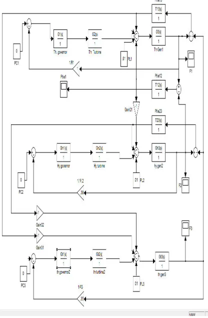
A three area thermal-thermal-thermal power system connected through a power line. Each area feeds its user pool and tie line allows the electrical power to flow between areas.
Figure 1: Three area Uncontrolled Interconnected Power system Model
FUZZY LOGIC CONTROLLER
The characteristics of the changing loads, complexity and multi-variable conditions of the power system limits the conventional control methods giving satisfactory solutions. Fuzzy logic is a thinking process or problem-solving control methodology incorporated in control system engineering, to control systems when inputs are either imprecise or the mathematical models are not present at all. Fuzzy logic can process a reasonable number of inputs but the system complexity increases with the increase in the number of inputs and outputs, therefore distributed processors would probably be easier to implement.
A fuzzy logic controller consist of three sections namely fuzzifier, rule base and defuzzifier. Fuzzification is process of making a crisp quantity into the fuzzy. If the form of uncertainty happens to arise because of imprecision, ambiguity, or vagueness, then the variable is probably fuzzy and can be represented by a membership function
Defuzzification is the conversion of a fuzzy quantity to a crisp quantity, just as fuzzification is the conversion of a precise quantity to a fuzzy quantity. There are many methods of defuzzification, out of which smallest of maximum method is applied in making fuzzy inference system [5]. The Fuzzy logic control consists of three main stages, namely the fuzzification interface, the inference rules engine and the defuzzification interface .For Load Frequency Control the process operator is assumed to respond to variables error (ACE) and change of error (dACE). The fuzzy logic controller with error and change in error is shown in fig.2.
.
Figure 2: Fuzzy Logic Controller
Nowadays fuzzy logic is used in almost all sectors of industry and science. One of them is AGC. The fuzzy logic controller designed for the system analysis
ISSN 2348 – 7968
Fuzzy Control Rules
A Ċ E
d A C E
NB NM NS Z PS PM PB
NB PB PB PB PB PM PM PS
NM PB PM PM PM PS PS PS
NS PM PM PS PS PS PS Z
Z NS NS NS Z PS PS PS
PS Z NS NS NS NS NM NM
PM NS NS NM NM NM NB NB
PB NS NM NB NB NB NB NB
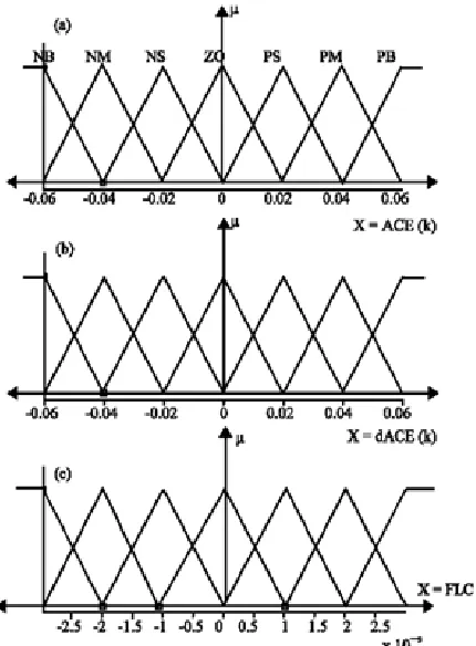
Here, seven membership functions have been used to explore best dynamic performance.
• Negative Big (NB) • Negative Medium (NM) • Negative Small (NS) • Zero (Z)
• Positive Small (PS) • Positive Medium (PM) • Positive Big (PB)
Fuzzy rules are conditional statement that specifies the relationship among fuzzy variables [3] .These rules help us to describe the control action in quantitative terms and have been obtained by examining the output response to corresponding inputs to the fuzzy controller.
Figure 3: Triangular membership functions a: input variable ACE, b: input variable (dACE), c: output variable
RESULTS & DISCUSSIONS
Simulations were performed using conventional PI and fuzzy logic controllers applied to a three area interconnected thermal system. Performance criteria such as settling time and overshoots were considered in the simulation for the system dynamic parameter.
By examining the results, conventional PI controller provides good control performance comparative to Fuzzy controller for the proposed model.
5.1 Three area interconnected uncontrolled thermal-thermal-thermal power system model
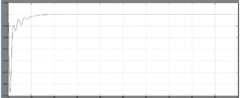
Figure 4: CHANGE IN FREQUENCY (F1) OF THERMAL1 w.r.t TIME
Figure 5: CHANGE IN FREQUENCY (F2) OF THERMAL2 w.r.t TIME
Figure 6: CHANGE IN FREQUENCY (F3) OF THERMAL3 w.r.t TIME
Figure 7: CHANGE IN TIE-LINE POWER OF AREA12 w.r.t TIME 5.2 Three area interconnected integral controlled thermal-thermal-thermal power system model
Figure 8: CHANGE IN FREQUENCY (F1) OF THERMAL1 w.r.t TIME
Figure 9: CHANGE IN FREQUENCY (F2) OF THERMAL2 w.r.t TIME
Figure10: CHANGE IN FREQUENCY (F3) OF THERMAL3 w.r.t TIME
Figure 11: CHANGE IN TIE-LINE POWER OF AREA12 w.r.t TIME.
In Figure 8, 9, 10, 11 Settling time for frequency deviation and tie-line deviation stabilization also varies for controlled system. Setting time is around 20-25 seconds.
5.3 Three area interconnected proportional integral controlled thermal-thermal-thermal power system model
Figure 12: CHANGE IN FREQUENCY (F1) OF THERMAL1 w.r.t TIME
ISSN 2348 – 7968
Figure 13: CHANGE IN FREQUENCY (F2) OF THERMAL2 w.r.t TIME
Figure 14: CHANGE IN FREQUENCY (F3) OF THERMAL3 w.r.t TIME
Figure 15: CHANGE IN TIE-LINE POWER OF AREA12 w.r.t TIME.
In Figure 12,13,14,15 Settling time for frequency deviation and tie-line deviation stabilization also varies for PI controlled system. Setting time is around 10-15 seconds.
5.4 Three area interconnected fuzzy controlled thermal-thermal-thermal power system model
Figure 16: CHANGE IN FREQUENCY (F1) OF THERMAL1 w.r.t TIME
Figure 17: CHANGE IN FREQUENCY (F2) OF THERMAL2 w.r.t TIME
Figure 18: CHANGE IN FREQUENCY (F3) OF THERMAL3 w.r.t TIME
CONCLUSION
In thermal-thermal-thermal based interconnected power plant, Oscillation in terms of overshoot and undershoot produced during initial period is comparatively more than uncontrolled area system. Settling time for frequency deviation and tie-line deviation stabilization also varies for integral controlled system. Setting time is around 20-25 seconds.
It has been observed that responses of frequency deviation with Fuzzy Controller are better in terms of steady state error, settling time, transients.
REFERENCES
[1] P. Kundur, Power System Stability and Control. New York: McGraw- Hill, 1994.
[2] P.Kundur, Power System Stability & Control. New York: Mc Graw- Hill, 1994, pp. 418-448.
[3] B. Anand and A Ebenezer Jeyakumar ‘Fuzzy Logic based Load frequency control of Hydro thermal system with Non linearities’ International Journal of Energy and Power Engineering 3(2):112-118, 2009
[4] Surya prakash & S K Sinha, ‘Load frequency control of three area interconnected hydro-thermal power reheat power system using AI and PI logic
controller,’International Journal of Engineering, Science & Technology, Vol 4 , No 1, 2011, pp 23-37 [5] Mukta, Balwinder Singh Surjan, ‘Grid stability of
Interconnected system with Fuzzy controller & HVDC in regulated environment ’, International Journal of soft computing & Engineering, ISSN:2231-2307, Vol-2, Issue -6, January 2013
[6] Rajesh Narayan Deo, Shiva Punjan Jaiswal, M. Venkateswarlu Naik ’Fuzzy Logic Based Automatic Load frequency control of Multi area power system’ International Journal of Power Electronics and Drive System, Vol.2, No.1, March 2012, pp. 67~75 ISSN: 2088-8694
[7] Atul Ikhe, Anand Kulkarni, Dr. Veeresh ‘ Load Frequency Control using Fuzzy controller of Two area thermal thermal Power System ‘ . International Journal of engineering technology and advanced Engineering, ISSN: 2250-2459, Vol 2, Issue 10, October 2012
[8] Shweta Bhardwaj, Charu Srivastava ‘Improving the Dynamic Performance of Interconnected Systems’ Int. J. Electrical Power & Energy Systems, 2014
[9] Kothari, D.P, & Nagrath, I.J., “Power system engineering”, second edition, Tata McGraw Hill. [10] D.P. Kothari and I.J.Nagrath. Modern Power System
Analysis. 4th Ed. New Delhi:McGraw Hill; 2010. [11] D. Das, J. Nanda, M. L. Kothari, and D. P. Kothari,
‘Automatic generation control of hydrothermal system with new area control error considering generation rate constraint,’ elect. Mach. Power Syst., vol. 18, no. 6, pp. 461–471, Nov. /Dec. 1990.
[12] Dr. T.K.Sengupta, “Studies on assessment of power frequency in interconnected grid its computer based control & protection”, 2008, thesis paper in JU.