NexPath Telephony Server
System Administration Guide
For Software Release 6.
THIS IS TO CERTIFY that the NexPath NTS Server hardware ("NTS Server") is hereby warranted to be free of all defects in material and workmanship for one (1) year from the date of initial purchase from an authorized dealer, but not withstanding this, no longer than 18 months after the date of original manufacture. This Warranty does not apply to a defect caused by negligence, misuse, accidents, acts of God, or to any use not in accordance with the instructions and specifications published by NexPath Corporation ("NexPath"). Use of the NTS Server in emergency or time-crit-ical or medtime-crit-ical applications is not appropriate.
During the period of this Warranty, NexPath will repair or replace at our service center located in Santa Clara, Califor-nia, any part proving defective in material or workmanship. All expenses related to replacing or repairing a defective part under this Warranty will be assumed by NexPath except for the cost of transporting the product to NexPath's ser-vice center, which shall be the responsibility of the buyer.
The buyer must notify NexPath of any defect, malfunction or nonconformity promptly upon discovery. Within 30 days after receiving the NTS Server from the buyer, NexPath will repair or replace the defective part, at its own option, pro-vided that NexPath has found the NTS Server to be defective. CUSTOMER'S SOLE AND EXCLUSIVE REMEDY HEREUNDER SHALL BE LIMITED TO THE REPAIR OR REPLACEMENT SPECIFIED HEREIN.
The foregoing warranties are contingent upon (1) the proper use of the hardware in accordance with the instructions and specifications published by NexPath, (2) the purchase of the NTS Server from a dealer or distributor authorized by NexPath to sell the NTS Server, and (3) return of a properly completed Warranty Registration Card within 30 days of purchase; and may not apply to any NTS Server that has been repaired or modified by persons other than NexPath. The NTS Server Limited Warranty is non-transferable.
BUYER AGREES THAT ITS EXCLUSIVE REMEDIES, AND NEXPATH'S ENTIRE LIABILITY WITH RE-SPECT TO THE NTS SERVER, SHALL BE AS SET FORTH HEREIN. BUYER FURTHER AGREES THAT NEXPATH SHALL NOT BE LIABLE TO BUYER OR ANY THIRD PARTY FOR ANY DAMAGES, INCLUD-ING ANY LOST PROFITS, LOST SAVINCLUD-INGS, OR OTHER INCIDENTAL OR CONSEQUENTIAL DAMAGES ARISING OUT OF BUYER'S USE OR INABILITY TO USE THE NTS SERVER OR THE BREACH OF ANY EXPRESS OR IMPLIED WARRANTY, EVEN IF THE BUYER HAS BEEN ADVISED OF THE POSSIBILITY OF THOSE DAMAGES.
THE EXPRESS WARRANTIES SET FORTH IN THIS AGREEMENT ARE IN LIEU OF ALL OTHER WAR-RANTIES, EXPRESS OR IMPLIED, INCLUDING WITHOUT LIMITATION, ANY WARRANTIES OF MER-CHANTABILITY OR FITNESS FOR A PARTICULAR PURPOSE.
NexPath Corporation 2972 Scott Boulevard Santa Clara, CA 95054
CHAPTER 1
Introduction
1
Intended audience 2 Requirements 2
Software version number applicable to this manual 3 Technical support 3
Legal Warnings 4
CHAPTER 2
Installation
5
Definitions 5
Verify that you have been shipped the following components: 6 Add the “base shoe” (optional, mini-tower systems only) 7 Determine a location for your system 7
Plan your wiring 8
AC power-fail bypass relays 8
Determining which jacks are to be used for hold music and the PA system 8
Hook the system up 8
Using punch-down blocks 12 Using 25-pair mini patch panels 13
Connecting outside lines, inside lines, hold music and paging to the system 14
Apply AC power 14
Test the system and the wiring 17
Change the system administrator and operator passwords (recommended) 18 Re-record the auto-attendant greeting (recommended) 19
CHAPTER 3
Network Installation
21
Information required 22
Connect the system to a network 23
Setting the IP address and other network parameters 23 Setting the network parameters using a floppy disk 24
Setting the network parameters using the NexPath Telephony Server Console 25 Setting the network parameters using the BOOTP/DHCP protocol 26
Testing your network connection 26
Using your System Name rather than the IP Address 27
CHAPTER 4
Software Configuration
29
Basic procedure for performing system administration 29 Starting AdminTool, the system administration program 31 Creating an editable configuration 34
Users, user names, and user permissions 37
Viewing, adding, editing, and removing user account information 39
Extension numbers 40
View, add, edit, or remove an extension number associated with an inside, outside, or public address (paging) line 42
Inside Line Extensions 43
Creating more than one extension per physical inside line 43 Announce Name 44
Call Waiting/ Caller ID 44
Outside Line Extensions 47 Public Address Extensions 47 Music on Hold Extensions 48
The parameters that can be defined for extensions assigned to outside lines 49
Voice mail 50
Speed Dial Extensions 54 Advanced Features 58 Line administration 59
Editing the parameters associated with each line 62 Centrex and CLASS Feature Integration 66 Music on Hold Input Line 67
Public Address (Paging) Output Line 67
Ring groups (Pickup Groups) 67
Pickup Groups are the same as Ring Groups 68
System limits 70
Seize order (Seize Groups) 73
Defining or changing the seize order 74
Access Authorization groups 75 Voice Mail Distribution Groups 78
To add a system voice mail distribution group 79
Setting the schedule for automatic switch-over between Day mode and Night mode 80
Associating an auto-attendant program with a configuration file 83 Activating a particular configuration file 85
Updating your software 86
Uploading and downloading files from the NTS server 86 Reviewing and/or changing the system time and date 87 Viewing Users Passwords 88
CHAPTER 5
Auto-Attendant Programs
89
Details of the actions that can be selected in the Action Menu page 95 Call Extension 97
Caller Enters Extension 98 Caller Makes Choice 100 Dial Tone 101
Disconnect Caller 101 Dial By Name 101 Jump to Previous Level 103 Call Distribution 105
IVR Features: Execute Program 111
Example: Re-creating the default auto-attendant program 114 Automatic Fax Detection 115
Recording Custom Greetings and Prompts 116
CHAPTER 6
Installing New Software Releases
119
The Software License Agreement 120 The contents of the CD-ROM 121
Determining your NexPath Telephony Server's Ethernet (MAC) address 122 Making a backup of an existing system’s configuration 123
Installing the NexPath Telephony Server software 124 Install the License key 127
Install the backup file (if you made one) 127 Finishing and verifying the configuration 127
Additional information for upgrading older systems (prior to Release 4) 128
CHAPTER 7
License Installation
129
Installing the license key from the License floppy disk 130 Installing the license key using ftp 130
CHAPTER 8
Using BackupTool
133
Creating a backup file 134
Copying the backup file to your local computer 139 Restoring from a backup file 139
CHAPTER 9
Troubleshooting
141
Initial start-up problems 141 Network-related problems 144
APPENDIX A
Specifications 147
System Hardware Features 147 Server Physical 147
Outside Lines (CO or Trunk Interface) 148 Inside Lines (Station Interface) 148 Network Interface 148
Server OS 149 Software Features 149
Regulatory information - Underwriters Laboratories 150 Regulatory Information- US Part 68, FCC Rules 150 Regulatory Information- US Part 15, FCC Rules 152 Regulatory Information- DOC CS-03 152
Legal Notices 153
APPENDIX B
Glossary 155
The NexPath Telephony Server combines all of the functions of a PBX, voice mail, attendant, auto-mated call distribution (ACD), and network-ready computer telephony server into a single, low cost, easily-maintained, completely integrated system.
The heart of the NexPath Telephony Server is a proprietary IBM-PC-compatible card which digitizes all incoming and outgoing calls. This card allows the system to take advantage of the power, reliability, and low cost of the ubiquitous IBM-PC platform, while allowing all of the advanced telephony features required in a modern phone system to be easily implemented. An additional bonus of using the PC platform and digitizing all telephone traffic is the simplicity and flexibility it allows when integrating the NexPath Telephony Server with other desktop computers within your organization.
Note This manual, along with all other system manuals, are available on the NexPath Telephony Server in Adobe Acrobat format, if you have a web browser and your PC is connected to the LAN. The URL for the list of manuals is http://<system name>/manuals/1. Other URLs that are useful are available on the NexPath Telephony Server at the URL http://<system name>/ or http://<system name>/help/.
The use of standard PC hardware in the NexPath Telephony Server also simplifies maintenance, since many components such as the hard disk, the power supply, the floppy disk, etc. are standard items available from
any PC supplier. NexPath provides all of the software necessary to completely reload the hard disk in the event of a component failure.
This manual describes how to install, configure, and maintain your NexPath Telephony Server. It expands on the concepts introduced in the NexPath Telephony Server User’s Guide. Please read and familiarize your-self with that manual before proceeding.
Intended audience
This manual is written for computer-literate personnel. It assumes that you know how to:
•
Connect computers to a network1and test network connections using “ping” or equivalent commands.•
Load and test Web browser software on the computers in your building.Because of the wide variety of networks packages and hardware platforms available, we cannot give explicit detail within this manual on how to perform these operations for your particular system. Check the manuals which came with your networking hardware and software, as well as the Web browser documentation, if you have problems in any of these areas.
This manual only covers the commands and procedures necessary to set up and maintain the NexPath Tele-phony Server.
Requirements
To install and maintain your NexPath Telephony Server, you will need:
•
A clean, dry location for the system with a source of 300 watts of 110V/60Hz AC power nearby.•
Twisted-pair phone wire to run to each telephone, FAX machine, or modem you are going to connect tothe NexPath Telephony Server.
•
In order to customize your telephone system, you will a computer with a TCP/IP-compatible network connection and Netscape Navigator 3.0 or later, or Microsoft Internet Explorer 4.0 or later, installed and Javascript enabled in the browser. At least one system should be connected to the NexPath Telephony Server over this network connection for system administration reasons.Software version number applicable to this manual
This manual is intended for use with software release number 2001.038.16 or later, generically known as Release 6. A later version number is indicated by a larger number in the second number position. You can check which version of software you are currently running on your NexPath Telephony Server in following ways:
•
By looking at the bottom of the AdminTool log-in page.•
By checking at the top of the main Menu page of AdminTool.•
By connecting a monitor to the VGA port on the back of the unit. The software Release and version num-ber should be displayed along with the current network parameter settings.If necessary, please contact NexPath support or your dealer, if you purchased from a dealer, for details on how to upgrade your system.
Technical support
Legal Warnings
The NexPath Telephony Server has many features that allow a business to adapt the phone system to their individual needs. However, not all features of the NexPath Telephony Server can be legally utilized in all localities. In particular, the feature of Listen-In to an on-going conversation without the consent of one or both parties may violate laws in your location. Also, programming the NexPath Telephony Server as an Automatic Dial and Announce Device (ADAD), using the LAN API, and using it for commercial solicita-tion or without the consent of the called party, is a violasolicita-tion of many state laws, and may violate federal law.
Probably the most time-consuming task when getting your new NexPath Telephony Server up and running is installing the wiring between your system and all of the phone lines it must support. This chapter covers that installation, along with other hardware-related setup issues. Software configuration is covered in the next chapter.
Definitions
In this document, we will use the term physical lines to refer to the twisted-pair telephone wires you will be connecting to the NexPath Telephony Server. Inside lines are the physical lines which you will run within your building and connect to your telephones, FAX machines, etc., while outside lines (or CO, for Central Office, lines) are the physical lines which come from the phone company. The actual number of inside lines or outside lines available in your system will depend on which configuration of the NexPath Telephony Server you purchased.
Note Line numbers are not the same as extension numbers! Extension numbers are the phone numbers a
other things, to identify which line a call is coming in on or which phone to ring when a caller dials a specific extension number.
Verify that you have been shipped the following components:
•
The NexPath Telephony Server computer itself with the appropriate number of telephone cards.•
The plastic base shoe for the NexPath Telephony Server computer with four 6-32 x 11/32” screws (mini-tower systems only).•
One RJ11-to-RCA-plug hold music cable (PN3100).•
An AC line cord.•
The NexPath Telephony Server User’s Guide.•
This book (the NexPath Telephony Server System Administration Guide).•
NexPath Telephony Server System Administration Guide Appendices, which contains detailed informationon settings and hardware configuration for each system type.
•
Several Quick Reference Guides, small booklets for each user to keep by the telephone.•
A warranty registration card.•
A two page Quick Start Guide with Survival Tips.•
Release Notes detailing information released after this manual was printed.•
A software package with a CDROM and two boot floppies.If purchased, the following optional components should be included in your package:
Add the “base shoe” (optional, mini-tower systems only)
If your system is a mini-tower system, included with your system is a rectangular piece of plastic, or “shoe,” which can be added to the base of the CPU chassis for additional stability, additional protection against dust, and additional protection against possible water damage.
To install this base shoe, perform the following:
1. Turn the unit upside-down on a piece of cardboard or some other soft surface so as to protect the finish on the top of the case.
2. Orient the base so that the arrows that are molded into the base are pointed towards the front of the unit and the word “Macase” that is molded into the base is visible. That is, the base should be attached so as to evenly widen the footprint of the unit.
3. Use the four screws supplied with the base to secure the base to the four pre-threaded holes on the bottom of the unit.
Determine a location for your system
While certainly not required, the NexPath Telephony Server is normally installed in a “phone room”, which is usually a small closet where the telephone company’s wires enter your building. This location must be dry and must have a source of either 110V/6A/60Hz or 230V/4A/60Hz AC power. The system should be installed off of the ground; either on a table or a shelf, and care should be taken so as not to block the vent holes on the system’s front and rear panels.
Plan your wiring
To plan your wiring, fill in the worksheet in the appendix to this manual that is appropriate to your system, taking into account the following constraints:
AC power-fail bypass relays
In the event AC power is lost, internal bypass relays on each card inside the system will automatically cause each outside line to be connected to a specific inside line so that basic telephone service is maintained during AC power failures. Before wiring up your system, decide which inside lines (i.e., telephones) you want to remain connected to the outside world in the event of a power outage. This information is in the wiring worksheet portion of the System Administration Guide Appendices manual. See the pages that are appropri-ate to your system (NTS/8 through NTS/136).
Determining which jacks are to be used for hold music and the PA system
Another constraint when assigning physical lines is that one outside line is usually configured as the audio output for a PA amplifier and another line is configured as a hold music input. By default, these are outside lines 1 and 4 respectively, though other outside lines can be used for this purpose, and outside lines 1 and 4 can be reconfigured as general-purpose outside lines during the software configuration process.
Hook the system up
Once you’ve filled out your wiring worksheet and determined which lines you want to go where, run twisted-pair phone wire to all of the locations you want serviced by the NexPath Telephony Server by run-ning the wires through your ceiling, walls, or floors.
Note To minimize the risk of fire, Underwriters Laboratories requires that 26AWG or heavier wire be used for all phone-line connections to the NexPath Telephony Server. In addition, all hardware used at the ends of the cables should utilize UL-recognized components.
to the two innermost pins of the jack. It is unimportant which of the two wires goes to which of the two cen-ter pins of the RJ-11 jack at the user’s end.
At the NexPath Telephony Server end, you will need to connect the twisted pair wires of the physical lines to the RJ-11 jacks on the back of the system using one of the connection methods described below.
•
Creating your own custom wiring and connecting directly into the back of the NexPath Telephony Server CPU.•
Using one or more RJ11-to-50-pin adapter cables with either new or existing punch-down blocks to bring each line of the NexPath Telephony Server CPU to its own pair of lugs, then cross-connecting from there to either existing punch-down blocks or wiring.•
Using one or more RJ11-to-50-pin adapter cables and 25-pair patch panels to bring each line of the Nex-Path Telephony Server CPU to its own RJ-11 jack.Note Be careful not to get electrocuted when connecting outside lines to your system! The telephone company will be supplying from 24 to 50 volts DC on all outside lines, with the voltage rising to approximately 90 VAC when a line is ringing!
Building custom wiring to plug directly into the back of the CPU
All physical line connections to the NexPath Telephony Server CPU are made through the RJ-11 jacks on the back of the NexPath Telephony Server CPU chassis. While these jacks look like (and are physically compatible with) the normal telephone jacks like those in a private home, with the NexPath Telephony Server, you cannot simply plug one telephone into each jack.
In the diagrams found there, the association of the line numbers listed with the pins inside the 6-contact RJ-11 jacks is as follows:
•
The line number listed first is connected to the innermost pair (i.e, pins 3 and 4) of the jack. These pins correspond to the red and green wires of a pre-assembled cable.•
A second line number, if listed, is connected to middle pair (i.e., pins 2 and 5) of the jack. In a pre-assem-bled cable, these pins correspond to the yellow and black wires.•
A third line number, if listed, is connected to outermost pair (i.e., pins 1 and 6) of the jack. In a pre-assem-bled cable, these pins correspond to the blue and white wires.So, for example, the jack for card 1 that lines up with the green dot on the lower edge of the case contains the pins for outside lines 2 and 3, with the innermost pair of pins in the jack corresponding to outside line #2, and the next pair of pins out from that inner pair corresponding to outside line #3.
Note The NexPath Telephony Server does not make a distinction as to which is the “tip” wire and which is the “ring” wire within a pair. That is, either of the twisted-pair wires of a given physical line can be connected to either pin of a pair (i.e., polarity does not matter).
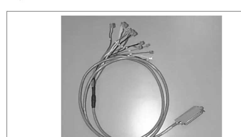
Adding RJ11-to-50-pin adapter cables
and patch panels. A typical example of this cable is pictured below (actual production may vary in appear-ance).
At one end of this cable are twelve RJ-11 plugs, each color-coded and numbered. At the other end is one male 50-pin connector.
To install the cable, plug each RJ-11 plug of the cable into its corresponding color-coded and numbered jack on the NexPath Telephony Server rear panel. For example, the green plug labelled “1” on the cable goes into the “green” jack of card 1, where the card numbers are listed below each card on the rear of the case and the color codes of the jacks are identified by dots at the bottom (or side) of the case. Each cable can bring out the RJ11 jacks of up to three cards. For cards numbered 4 and higher, connect cable #1 to card 4, #2 to card 5, and #3 to card 6, and similarly for groups of three cards until all cards are connected.
See the appendix to this manual that is appropriate to your system for details of the pin-outs of the 50-pin ends of these cables.
Using punch-down blocks
Many phone rooms use punch-down blocks to connect the lines of a company’s phone system to the com-pany’s PBX, voicemail server, and other components of their system. A picture of the punch-down block available from NexPath is given below (actual production may vary in appearance).
With punch-down blocks, single-strand 24 or 26 AWG phone wires are impaled (“punched down”) on lugs which in turn are connected to the components of the phone system either through more solid wire or by bringing groups of the lugs together to 50-pin (i.e., 25-pair) connectors and going from there either to other punch-down blocks or to the components of the phone system through one or more bundled cable(s). You “punch-down” the wire on the lugs of the punch-down blocks (hence the name) using a punch-down tool such as the AT&T Type AT-8762D.
Note You will have to either create custom wiring as described under “Building custom wiring to plug directly into the back of the CPU” on page 9 or use the RJ11-to-50-pin cables described in “Adding RJ11-to-50-pin adapter cables” on page 10 to bring the lines from the rear of the NexPath Telephony Server to your punch-down blocks.
Using 25-pair mini patch panels
Another method for connecting to the NexPath Telephony Server is to use the RJ11-to-50-pin cable described in “Adding RJ11-to-50-pin adapter cables” on page 10 in conjunction with a 25-pair mini patch-panel. A picture of the 25-pair mini patch panel is shown below.
If you then add an RJ11 jack to each physical line coming into your phone room, you can plug these jacks into the patch panel(s) per the patch panel break-out diagrams in the System Administration Guide
Appendi-ces that is appropriate to your system.
Connecting outside lines, inside lines, hold music and paging to the system
Connect your physical lines to the NexPath Telephony Server using one of the methods described above. Note that outside lines will be seized in reverse-line-number order (for example, for a system with six out-side lines, the CO line plugged into outout-side line 6 will be seized first. The next line seized will be outout-side line 5, etc.).
If your company has a paging system, connect the paging output of the system to the line-level input of the paging amplifier. Outside line 1 is used as the system’s paging output in the default system configuration.
If you have a two-card (NTS/16) or larger system, you can also connect a hold music source (such as a radio) to the system by using the hold music cable (PN3100) and connecting it to the system’s hold music input1. You may want to adapt the headphone jack of your radio or receiver to the phono-plug input of this cable so that you can control the volume of the hold music (line-level outputs receivers are not controlled by the vol-ume knob).
Note You can connect music on hold to the single card system, the NTS/8, but you must use AdminToolTM and the LAN interface to change the designation of CO line 1 from a PA output to music on hold input. See “Editing the parameters associated with each line” on page 62 for more details.
Note The hold music cable contains internal amplitude-limiting diodes, and must be used to insure that the system meets all FCC requirements.
Apply AC power
Use the AC line cord supplied with your system to connect your NexPath Telephony Server to an AC outlet capable of supplying either 6 Amps at 110V/60Hz (that is, 660 Watts) or 4 Amps at 230VAC/60Hz (i.e., 920 Watts) AC power. To minimize the risk of local lightening strikes or other electrical surges damaging your system, you may want to install an AC surge arrestor at the AC outlet.
Alternately, you may want to use an uninterruptible power supply (UPS) with the NexPath Telephony Server. Using a UPS gives you time to shut down the system gracefully in the event of power failure so that voice mail messages or other information recently recorded is properly saved to the system’s hard disk.
Furthermore, while any UPS capable of supplying at least 600 Watts can be used, NexPath recommends using an APC SmartUPS SU1000 or APC Back-UPS Pro EP1000. The APC UPS should be connected to the NTS with NexPath UPS Cable Part # 3290 (special order).
Note Do not connect the cable that came with the UPS. The APC 940-0020C cables can cause the NexPath Telephony Server to prematurely shutdown as soon as it boots and interfere with the NTS Reset button operation.
The cable to connect an APC UPS to the NexPath Telephony Server is constructed as shown below in Figure 2-4 (note that a 1.2 kilohm resistor is required from pin 7 to pin 1 on the NTS end).
By connecting the correct interface cable between the Computer Interface Port of the APC UPS and the DB9 connector labelled “COM2” on the back of the mini-tower NexPath Telephony Server (COM1 on rack mounted systems), the UPS will signal the NexPath Telephony Server when AC power is lost and the battery is low, and the NexPath Telephony Server will automatically perform a graceful shutdown, and then turn the UPS off. Some UPS units (e.g., the APC BackUPS 650), do not have a delayed shutdown, and will turn off immediately when signalled by software. These units must leave the Shutdown UPS signal (Figure 2-4) dis-connected, or disable the UPS shutdown command using the Console program (see next paragraph). Other-wise the UPS will turn off before the software has completely synchronized the hard disk. Also, if the UPS
PC (NTS)
Female DB-9
UPS
Male DB-9
4 (DTR) 1 (Shutdown UPS)
8 (CTS) 2 (No AC)
5 (GND) 4 (GND)
1 (DCD) 5 (Low Battery)
7 (RTS) N/C
FIGURE 2-4: APC UPS to NTS Interface Cable
1.2
is not turned off when the software shuts down, it will require operator intervention in the event of a loss of AC, to reboot the NTS. The best choice of UPS’s are units similar to the SmartUPS which have delayed shutoff and can be turned off by the software.
You can adjust the UPS shutdown parameters using the NexPath Console. Further details are provided in the Console screens. Information on connecting a VGA monitor and keyboard to access the console are pro-vided in the section
Setting the network parameters using the NexPath Telephony Server
Con-sole
on page 25. UPS settings entered with the console take effect immediately and do not require a reboot of the NTS.Note To meet UL requirements, a second ground connection must be connected to the case of the NexPath Telephony Server in case the earthing connection in the AC cord is miswired or fails. To make this connection, attach one end of a 16 AWG or heavier wire to a source of earth ground and the other end to the ground lug located on the rear of the case near the power supply fan.
After wiring the system to a source of AC power, boot up the system by turning on the UPS (if used) and pressing the AC power switch on the front panel of the NexPath Telephony Server. Allow about two minutes for the system to come up fully. You can tell when the system is finished initializing by listening for a dial tone on an inside line that is not otherwise bypassed to an outside line during the power-down state.
Test the system and the wiring
Test all inside lines by picking up each inside line telephone, checking for dial tone, then entering the Announce Line and Extension Numbers sequence and verifying that each phone is connected as planned in your wiring worksheet.
To test the outside lines, pick up telephones on as many inside lines as you have outside lines and press to seize outside lines on all of them.
Test your paging output (if connected) by picking up an inside line, dialing the default paging extension 111, and making an announcement.
To test your hold music input (if used):
•
Have someone call in from outside your building.•
During the auto-attendant greeting, have them enter your extension number.•
While talking to them, put them on hold using the Put Call on Hold sequence . You should hear a dial tone while they are on hold.•
After a few seconds, take them off of hold by entering the Retrieve Call from Hold sequence and verify that they heard hold music.You can also test hold music by assigning an extension to the hold music line, as described in “Music on Hold Extensions” on page 48, and dialing this extension number from any telephone.
If the system fails any of these tests, check the chapter Troubleshooting for information. If that chapter either doesn’t address or doesn’t solve your problem, contact your dealer or NexPath telephone support for assistance.
Note Hold music only works if (1) the line that is put on hold has been configured for hold music (See Line administration on page 59 in the chapter Software Configuration), and (2) the hold sequence above (or transfer to park orbit, or placed in queue in an ACD group) is properly entered. In particular, the HOLD button on a regular telephone will not work, since the NexPath system has no knowledge that this button was pressed. Only the Hold Sequence above can be used, or similar sequence from network programs such as NexDial, NexDirector, or TelOper.
# 8
9
Flash 1
Change the system administrator and operator passwords (recommended)
To protect your system from inadvertent changes or other meddling, we recommend you change the system administrator password and operator passwords as soon as possible. To change the system administrator password:
1. Pick up an inside line.
2. Enter the Change Password sequence .
3. At the prompt, enter the factory-default for the system administrator’s password (1000), then enter a new password that only you will know about.
Repeat the operation to change the operator’s password (the factory default for the operator’s password is 1099).
Note Do not forget the new system administrator password! The system administrator has the necessary privileges to reset other user’s passwords if they get lost, but if the system administrator password gets forgotten, you will have to re-install the software or contact NexPath for help in restoring the original password file!
If you wish, you can record your new system administrator password here, to avoid forgetting it: System Administrator Password: ___________________.
Re-record the auto-attendant greeting (recommended)
The factory default configurations for both the day-mode and night-mode auto-attendants are as follows:
You may want to use this information to re-record the auto-attendant greeting to be more meaningful for your company’s configuration (for example, add something like, “Press 1 for Dave”). To change the greeting heard by people calling in from outside while the system is in Day Ringing mode, do the following:
Note The following will not work if you have activated a configuration using a web browser from the network. The connection between extension 130 and 131, and the day and night mode greetings is setup by the factory, and is deleted after the first network activation of a configuration. From then on, you must use the web browser and the AdminTool software. See the chapter Auto-Attendant Programs starting on page 89.
1. Press the Enter Password sequence .
2. When prompted, enter the system administrator’s password (the default is 1000).
3. When the system announces that your password is accepted, dial 130, which is the day auto-attendant’s voice mailbox extension number.
An incoming
caller enters The call is connected to
0 Operator (extension 300)
1 Extension 301
2 Extension 302
3 No action (waits for rest of extension number). Incorrect or incomplete entries take the caller back to the beginning of the auto-attendant greeting.
4 Extension 304
5 No action (waits for rest of a voice mail extension number). Incorrect or incomplete entries take the caller back to the beginning of the auto-attendant greeting. 6 Extension 306 (dials the operator in NTS/8 systems)
7 Extension 307 (dials the operator in NTS/8 systems) 8 Extension 308 (dials the operator in NTS/8 systems)
9 Operator (extension 300)
* Operator (extension 300)
# Operator (extension 300)
4. After the system announces the number of messages, press and then select the main greeting, then record a new greeting when prompted.
5. This approach will change the auto-attendant greeting to your own recording, but will only work if you have never activated a configuration from the network. See the note above.
Operation for the Night Ringing greeting is similar, except the Night Ringing voice mail extension is 131.
Connecting the NexPath Telephony Server to the network is essential if you wish to access the most impor-tant features of the system. A network (also called LAN or TCP/IP) connection is required for email notifi-cation from voice mail, to customize the system configuration, and to use client software programs such as NexDial and NexDirector.
However, a network connection is not mandatory; the NexPath telephone system will function in its entirety (except for email notification) with the LAN cable disconnected. So it is possible, for example, to connect the network and configure the system using a web browser from a client PC, and then disconnect the net-work.
Information required
The following information is required to as a minimum connect your system to the LAN:
IP Address for the NexPath System: _____._____._____._____
Netmask for the NexPath System: _____._____._____._____.
The netmask defaults to 255.255.255.0. It is used to determine the range of IP addresses that can be con-tacted directly on the local subnet, and which IP addresses must be concon-tacted through a router or gateway.
If you want to access your NexPath system from outside of the subnet that the NexPath is on, such as at a location from the Internet, or, if your NexPath system must contact a mail host outside of your subnet (as set by the netmask above), then you need the following:
Gateway (also called a router): _____._____._____._____.
If you are going to use email notification, many mail servers require a valid domain name. The NexPath Telephony Server only programs a domain name when the DNS (Domain Name Server) IP address is also programmed.
IP address for the Domain Name Server: _____._____._____._____.
Domain Name: ____________________.
If you do not know or understand the above parameters, then you should obtain the assistance of a network consultant or your Internet Service Provider. Many ISPs provide assistance to their customers in setting up various network devices.
Connect the system to a network
To physically connect your system to a network:
1. Connect the necessary physical wiring to the 10BaseT (RJ45) connector on NexPath Telephony Server’s built-in LAN card. If you are not already using 10BaseT connections in your network, you may need an AUI-to-10BaseT or a BNC-to-10BaseT adapter to complete the connection. Some NexPath Server mod-els have 10/100BaseT auto-sensing LAN connections. Be sure to use a standard network cable to con-nect to a hub, or a special cross-over cable if you are concon-necting the NexPath Telephony Server directly to another computer without a hub.
Note Do not use the BNC connector (if present) on the LAN card to connect the NexPath Telephony Server to your network. The NexPath Telephony Server software does not support this connector.
2. Set the network parameters as described in the next section.
Setting the IP address and other network parameters
You can set the network parameters on the NexPath Telephony Server in one of three ways: 1. Using a DOS formatted floppy disk.
2. Using the NexPath Telephony Server console, which is accessed using a standard PC keyboard and VGA monitor connected to the NexPath Telephony Server.
3. Usingbootp, a subset of the DHCP protocol. Thebootpprotocol must first be enabled using the con-sole or a floppy disk. By default, it is disabled on the NexPath Telephony Server. You should only use
bootpif you are a network expert and very familiar with network issues, since a static IP is best for the NexPath system The IP address of the NexPath system must be known by all users of the network inter-face in order to communicate with the server. Dynamic IP assignment makes this much more difficult unless your DHCP settings are automatically propagated to DNS.
The network settings from the floppy/console andbootpare stored in separate files on the hard disk and used each time the system is booted. The following order is used to set the network parameters for each boot sequence. If a valid IP address is not obtained at one step, the next in the sequence is tried:
2. The last setting from the floppy or console (both change the same file), 3. The last setting whenbootpwas answered.
Most NexPath users will set the network parameters using either the floppy disk or the console. Only net-work experts should consider usingbootp. Note that the local timezone can only be set from the floppy disk or the console, not frombootp.
If all of the above attempts to set the IP address fail, then the IP address defaults to 192.168.0.2 with a sys-tem name of nexpath.
Setting the network parameters using a floppy disk
1. If your system is not already up and running, turn it on and wait about two minutes (i.e., until the soft-ware finishes initializing).
2. Insert a blank but pre-formatted, writable DOS-compatible floppy disk (must be a 2HD or 1.44MB floppy; other formats will not work) into the NexPath Telephony Server’s floppy drive.
3. Press the RESET switch (or NTS Reset button, or small red reset switch on some older models) on the NexPath Telephony Server front panel.
4. The system will indicate that it is done copying the template file to the floppy by beeping 10 times. Remove the floppy disk when the system beeps.
5. Take the floppy to a DOS-compatible system and use a standard text editor such as DOS’s EDIT.COM or Windows Notepad to edit the file SETUP.TXT on the floppy. This file will have instructions and key-words for setting the network parameters as described above. You can also set the local time zone using this floppy.
6. When you have finished editing the file and saved the results to the floppy, take the floppy back to the NexPath Telephony Server and insert it in the floppy drive.
7. Press the RESET switch (or NTS Reset button, or small red reset switch on some models) on the front panel again.
8. When the Status LED on the front panel begins to flash red and green, remove the floppy disk.
9. Press the RESET switch (or NTS Reset button, or small red reset switch on some models) one more time, and wait for the system to re-boot, and the software to re-initialize (1-2 minutes).
Note If the NexPath Telephony Server has trouble with the information added to SETUP.TXT in step 5, it will create a problem report file on the floppy called LOG.TXT.
Note If you ever need the LAN hardware interface address (MAC address), it is written on the floppy in a file named ADDRESS.TXT. It is also available on the screen, if you connect a VGA monitor to the NexPath Telephony Server. You can also find the MAC address on the label on the back of the system.
Setting the network parameters using the NexPath Telephony Server
Console
To use the NTS console, you must connect a standard PC keyboard, and a VGA compatible monitor, to the NexPath Telephony Server. A console should appear, that has menu items that can be accessed using the arrow keys on the keyboard. More information on using this console is available under the Help menu item.
Network parameters (including the local time zone) that are changed using the NexPath Telephony Server console do not take effect until the system is rebooted. You can reboot the system by pressing the Reset but-ton, or by selecting Restart on the Operations menu on the console. Either method will immediately discon-nect any calls in progress. Your users will lose dial tone for 1-2 minutes.
Setting the network parameters using the BOOTP/DHCP protocol
Whenbootpis enabled (it is disabled by default), the NexPath Telephony Server will issue abootp
broadcast during the first 30 seconds of boot initialization. If the broadcast is answered by abootp/dhcp
server, then the NexPath system will set its network parameters based on this information provided in this protocol. The following parameters can be set usingbootp:
1. System name 2. System IP address 3. Router (gateway) 4. DNS Server 5. Subnet Mask
If the IP address is supplied bybootp, then all of the parameters are set bybootp, and these will override any console or floppy settings. The system will beep three times if the network IP address is set via the
bootpprotocol. Only network experts should consider using thebootpprotocol. Note thatbootpis by default disabled, and can only be enabled from the Console or by using the floppy disk (see “Setting the IP address and other network parameters” on page 23).
Testing your network connection
Check with your network administrator to see if the “ping” command is available on your computer. If so, issue the following command from your computer:
ping <NexPath Telephony Server system IP address>
where <NexPath Telephony Server system IP address> is replaced above by the IP address that you assigned the NexPath Telephony Server in step 5 of “Setting the IP address and other network parameters” on page 23. You should get a response similar to:
<NexPath Telephony Server system IP address> is alive
Next, in a web browser, open the URL:
For example, if you gave your NexPath Telephony Server IP address of 192.168.0.2, you would open the URL:
http://192.168.0.2/
The NexPath NTS Server main page should appear. Check in the chapter
Troubleshooting
if you have problems “pinging” the NexPath Telephony Server or opening the URL.Note You can also assign the NexPath Telephony Server a system name, to make it more convenient to type in the web browser. This name can only be used if you have programmed thehostsfile or setup DNS with the host-IP Address correspondence. Otherwise, use the IP address of your system for all URLs, and be sure to include a trailing slash “/” for all URLs. See the next section.
Using your System Name rather than the IP Address
In order to use a system name to refer to the NexPath Telephony Server, rather than the IP address, in pro-grams such as the Netscape web browser and other network tools, you should put the IP address to system name correspondence in your DNS (Domain Naming System) Server. If you do not have a DNS Server, or do not know what this is, you can still use the system name by putting the information in thehostsfile on each client computer on the network. Thehostsfile is a text file located atC:/Windows/hostson Win95/Win98/WinME, and atC:/Winnt/system32/drivers/etc/hostson WinNT4.0/Win2K. You can create this file using Notepad or Wordpad, but these programs may insist on putting a “.txt” at the end of the filename. You must rename it to just plainhosts(no extension) for it to work, using the Win-dows File Explorer. Also take care that you are not using the hosts.sam file, which is a sample file Microsoft puts on the system. The filename must behosts (upper or lower case does not matter) with no file extension. You can copy the hosts.samfile to a file namedhosts, and edit this to make things sim-pler. The contents of the file should be similar to the following:
127.0.0.1 localhost
192.168.0.2 nexpath
Note When you assign the IP address to the NexPath system, using any of the methods on page 23, there is also a place to enter the system name. Actually, this name is only used locally on the NexPath system and can be anything you choose. The only time a name is used in TCP/IP protocols is when a DNS server is contacted to convert a name to an IP address. Otherwise, only numbers (IP addresses) are used in TCP/IP communications. NexPath recommends that you use the same name on the NexPath Telephony Server, thehostsfile, and DNS (if used), to avoid confusion, but there is no requirement that all of these names have to agree.
After you create thehostsfile, it is not necessary to re-boot Windows to get programs to use it, but you must exit and re-start any program that is already running. For example, if Netscape was running when you changed or created thehostsfile, then you must exit Netscape and re-start it in order for it to use the new information in thehostsfile
According to the Microsoft manual, Windows may not look at thehostsfile unless DNS is enabled. You can enable DNS by putting in a Domain name and Host name in the Windows networking TCP/IP setup page under the Control Panel -> Networking folder. It is not necessary to put in a DNS Service Search Order IP address, unless you have a DNS Server.
Though the NexPath Telephony Server comes pre-configured for use right out of the box, you may find that you want to make changes to the configuration so that the system better meets your needs. Configuration changes are accomplished via a web browser from a LAN connected PC. Access to the NexPath Telephony Server from a console CRT and keyboard directly connected to the system is for setting network parameters only.
Note Except for changing greetings and passwords, modifying the bulk of the telephone system’s
configuration requires that you connect the NexPath Telephony Server to a desktop computer using a TCP/IP network connection. You will also need a Netscape 3 or later, or Microsoft Internet Explorer 4 or later, web browser. See the chapter Network Installation starting on page 21 for information on how to connect the NexPath Telephony Server to a network and test the connection.
Basic procedure for performing system administration
We recommend you perform the following steps when creating a custom configuration for your system: 1. PLAN YOUR SYSTEM! It is a lot easier to make changes on paper than it is to perform multiple
Note You will find it extremely helpful later if you create a complete list of all users and their extension numbers you plan on having in the system, along with what line and/or voice mail box each is associated with. Also, make sure that you are assigning inside lines such that, when AC power to the NexPath Telephony Server is turned off, the power-fail bypass connections made between outside lines and inside lines will leave the desired group of phones connected to the outside world.
2. Create an editable configuration file (see “Creating an editable configuration” on page 34).
3. Make any changes or additions to the access authorization groups (see “Access Authorization groups” on page 75), then perform user administration (see “Users, user names, and user permissions” on page 37). Remember that at least one user should have system administration privileges, and that one user may own more than one extension and/or voice mailbox.
4. If you are going to use ring groups, create or modify the ring groups (see “Ring groups (Pickup Groups)” on page 67). This step is a bit tricky, because you have to know what lines will be going to which desk before you can create the ring groups, plus you have take into account the NexPath Telephony Server’s power-off bypass connections between outside lines and inside lines when deciding what inside line to assign to which extension.
5. Make any changes or additions to the Extensions as required (See “Extension numbers” on page 40). In particular, you will want to change the name of the extensions so that the Dial By Name auto-attendants will function for your company. See Dial By Name on page 101 in the chapter Auto-Attendant Pro-grams for more details.
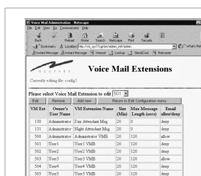
6. Make any changes or additions to the voice mail boxes (see “Voice mail” on page 50). You may want to change the maximum message size or total mailbox size of various voice mail boxes.
7. Perform line administration (see “Line administration” on page 59). In particular, make sure the central office line type (CO line type) is correctly set for your system.
8. Create your auto-attendant(s) and associate them with extensions in your configuration (see “Associating an auto-attendant program with a configuration file” on page 83).
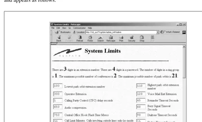
9. Enter any final details of your configuration (see “System limits” on page 70 and “Seize order (Seize Groups)” on page 73).
Starting AdminTool, the system administration program
Configuration and administration of the NexPath Telephony Server is done using a Web browser to access the AdminToolTMprogram.
To start AdminToolTM:
1. Start you web browser on a computer which is connected to the NexPath Telephony Server over the net-work.
2. Select “Open URL” in your Web browser.
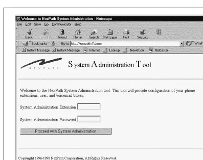
3. Specify the location to open as http://<system name>/Admin/. Note the capital “A” in Admin. The trailing “/” is required if you are using an IP address instead of a system name. The follow-ing screen should appear within your browser:
4. Enter an extension number and a password which has been assigned system administration permissions. Any valid system extension can be used (such as 301), but we suggest you use the extension number of the telephone near your computer. The extension you login with will be the one that the software expects to be used for recording custom messages. (The factory default password is 1000, though we suggest you change the default password as soon as possible to avoid unauthorized access to your system).
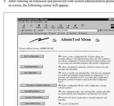
5. After entering an extension and password with system administration permissions in the AdminTool log-in screen, the followlog-ing screen will appear:
Creating an editable configuration
The NexPath Telephony Server uses configuration files to specify such things as what extension numbers are valid in your system, which phone or phones will ring when a specific extension is dialed, who has a voice mailbox, who does not, and all other items (with the exception of the auto-attendant programs) that define your NexPath Telephony Server’s “personality1.”
You can create and maintain multiple configuration files, and then switch between them by selecting and activating any one of them. One important note: when you select and activate a specific configuration file; it is copied to a special file named “config”. This is intended to help avoid confusion as to which file is active. This special configuration file can be viewed using the same tools available for creating new configurations, but it will not be editable.
When you first begin system administration, the only file listed in Configuration File Administration page is the file “config”, which in turn holds the default configuration. You can create a new configuration from scratch using the Create new configuration button, or you can use the default configuration as a starting point. NexPath recommends that you make copies of the default configuration, and use this as a starting point, until you become familiar with the system. The Create new configuration option makes a rather empty configuration file, with no extensions filled in, and is for situations where you intend to completely change the system number plan.
To use the default configuration as a starting point, though, you must first copy “config” to a new file for editing. To create an editable version of the “config” file:
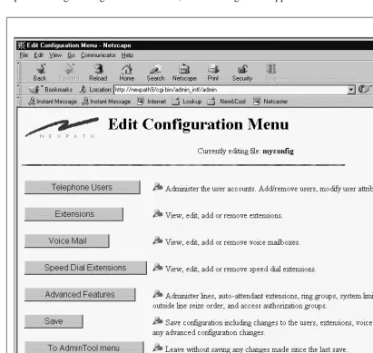
1. From the AdminToolTMMenu, click the Edit Configuration button. 2. Click on the file “config”, then click on Edit selected file. 3. Click on Save in the Edit Configuration menu.
4. Add a new file name in the Save file as box (for example, “myconfig”), then click on Save, return to the AdminToolTMmenu to return to the AdminTool menu, or on Save, return to the Edit Configura-tion menu to edit your new file.
Note We recommend you copy the default “config” file to a file called “default” before creating any other editable files, and then create a second, working copy with a different name for your edits. This way, you can get back to the default configuration at some future time if necessary. Standard
configuration files are also on the CDROM that came with your system, under the directory Release 6/
Support, which can be uploaded to the server using the procedures described in “Uploading and
downloading files from the NTS server” on page 86.
Changes can be made to your new, editable file and then the new file can be scheduled to become the run-ning configuration using the Activate or Update Software procedure. See “Activating a particular configu-ration file” on page 85 for details. Editing a configuconfigu-ration file has no effect on the running system until this file is activated using the Activate or Update Software procedure.
Note If no auto-attendants are defined, activating your first configuration as described above will cause the NexPath Telephony Server to perform all the necessary steps to copy the default day and night auto-attendant programs to the files Day_Program.aa and Night_Program.aa, respectively. These files will be associated with extensions 120 and 121, respectively, in the configuration you are activating. Also, the voice prompts recorded in the voice mailboxes at extensions 130 and 131 will be copied to the audio files GeneralGreeting.au and GeneralNightGreeting.au, and these audio files will be used as the greeting for the auto-attendant files created. These prompts can be re-recorded and customized using the Auto-Attendant -> Audio Processing page, as described on Recording Custom Greetings and Prompts on page 116 in the chapter Auto-Attendant Programs.
Upon selecting a configuration file to edit, the following screen appears:
Users, user names, and user permissions
The NexPath Telephony Server cannot tell, when someone picks up a telephone on a desk, whether that someone is the CEO of the company or the night janitor. To help determine who is using the system, the NexPath Telephony Server uses the concepts of individual users, where each user has a unique password and can be assigned an appropriate set of permissions.
Users are identified by their password. The password is used for logging into LAN based programs such as AdminToolTM, for accessing voice mail, and for providing permission to make changes to extensions such as forwarding calls, or permissions to make long distance calls.
An inside line in the system has a set of default privileges, and the system uses these default privileges when that phone goes off-hook and a call is attempted. A user can gain access to his or her own privileges by entering the password sequence and then the password, as described in the Users Manual, to go under “password protection”. From then on, until a hang-up, the line has the privileges of the user whose pass-word was entered.
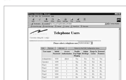
Specifically, each user account within the NexPath Telephony Server is assigned the following parameters:
•
An initial password. The value of the initial password is set by the system, and cannot be changed fromAdminToolTM. Instead, users should be instructed to change their passwords as soon as possible so that no one else can, for example, access their voice mail.
•
Access authorization, where users can be allowed to make any long distance call, no long distance calls, or only long distance calls to within the area codes defined in a specific access group. Access groups are defined using the operations described on “Creating and modifying the access authorization groups” on page 77.Access authorization permissions for individual users are particularly useful in the following circum-stance: if you configure your system so that, say, the inside line connected to your lobby phone has all long-distance calls blocked (as described in “Line administration” on page 59), then a user with wide-ranging access authorization can override the phone’s block on long distance calls by picking up the phone, then identifying himself to the system by entering and his password, then dialing to seize an outside line and then dialing his number.
•
Enable day/night ringing. Users who have this permission can switch the system between the Day mode and Night mode. Both lines and extensions (covered later in this chapter) have parameters, such as which phone to ring when an extension is dialed, that can be take on different values depending on whether the system is in the Day mode or the Night mode.# 3
•
Admin privileges. Users with admin privileges can perform phone system administration. Only users with admin privileges can access AdminToolTM. Additionally, users with admin privileges can access all voice mailboxes, set and cancel call forwarding for any extension, and have access to all other user’s pass-words.•
Barge-in/ Listen-in. Users with this permission can barge into, or listen into, other party’s calls by enter-ing the barge-in sequence and an extension number, or the listen in sequence ,. This does not affect the ability of a user to listen-in or barge-in to his or her own voice mail; it only applies to two party calls or mailboxes not owned by the user. WARNING: Listening-in to a conversation without thecon-sent of one or both parties may be a violation of local, state, and federal privacy laws. It is the responsi-bility of the user of the NexPath Telephony Server, when using features of the system, to assure that he or she is in compliance with all applicable laws.
•
External features. This permission field is not currently in use, but is reserved for future product enhance-ments.Note While users must be defined in the system before they can be assigned an extension number or voice mailbox, they do not have to be assigned an extension number or voice mailbox. For example, many people configure their systems with only one user account (and therefore only one password) having admin privileges, but do not then assign this user account to any extension numbers.
The Telephone Users screen is accessed from Edit Configuration -> Telephone Users and appears as fol-lows:
Viewing, adding, editing, and removing user account information
To view, add, edit, or remove user accounts:
1. From the AdminTool menu, click on Edit Configuration.
2. If the only file listed is “config”, create an editable file per the instructions in “Creating an editable con-figuration” on page 34.
3. Click on the configuration file you want to edit, then click on Edit Selected File. This will bring up the Edit Configuration menu.
4. Click on Telephone Users. A list of all users defined for the configuration selected is shown.
5. Click Add new to add a new user, or select an existing user account from the pull-down list of users and click Edit to edit the user’s permissions or Remove to remove the user.
Note If you are using the default configuration and want to change the user names to be more descriptive, you can determine which user names are currently being used for the names you want to change by comparing the passwords for each user as shown in the wiring worksheet against the initial password column of the Telephone Users page.
Note Before a user can be removed, all extensions associated with the user must be removed. When you click on Remove, a list of the extensions still associated with this user will be displayed. See “Voice mail” on page 50 for information on removing or re-assigning these extension numbers.
6. If creating or editing a user’s account, review/change the user’s permissions in the Modify Telephone Users and/or Attributes page that appears, then click Keep changes and return.
7. Continue adding, editing, or removing user accounts until you are satisfied with the information dis-played in the Telephone Users page.
8. SAVE YOUR EDITS! If you are done editing the configuration, work your way back to the Edit Configura-tion menu and click on Save there, entering a file name in the Save file as box (the file name can be the same as the file you just edited). After entering a file name, click on Save, return to the AdminTool menu. You will also need to schedule your altered configuration file to be activated as outlined in “Acti-vating a particular configuration file” on page 85.
Note After removing a user, all voice mail associated with the user will be removed when the new configuration is activated.
Extension numbers
The NexPath Telephony Server allows you to assign extension numbers to:
•
Inside lines, where dialing the extension number associated with a particular inside line will ring the phone (or FAX or modem) at that inside line.•
Paging (public address) lines. One line per CBTI card can be configured to support public address pag-ing. By dialing the extension number of the paging line, you will connected to the PA system. An exter-nal amplifier is required.•
Voice mailboxes. Users can get into their voice mailboxes by dialing their voice mailbox extension num-ber, pressing during their greeting, then entering their password during their greeting.•
Auto-attendants. To enable an auto-attendant program file, the NexPath Telephony Server requires that you associate the attendant program with an extension number. The extension number of the auto-attendant can be dialed from any line to activate the auto-auto-attendant program. Many different auto-atten-dant extensions can be created and associated with various auto-attenauto-atten-dant programs. The default config-uration creates extensions 120 and 121 as the default Day and Night auto-attendants.•
Speed Dial Extensions. Speed dial extensions translate a three digit number to a seven or more digit number for off-site dialing. They can be used to simplify off-site calls, or as a means of dialing off-site numbers from an auto-attendant.•
Park orbits. Park orbits are a kind of public hold, where a call can be parked and picked up in another location.•
Ring groups. Extensions are associated with ring groups for either the Day mode, Night mode, or both, and will ring all of the phones in the ring group when this extension is dialed.•
ACD (Automated Call Distribution) Groups. ACD groups are accessed through auto-attendants. See the chapter Auto-Attendant Programs starting on page 89.Note The AdminToolTM->Edit Configuration->Extensions page described in this section is used only to administer the extension numbers associated with inside lines, outside lines, and public address (paging) outputs. Administering the extension numbers associated with voice mail boxes is described in “View, edit, add, or remove voice mailboxes” on page 53, while the assignment of extension numbers to auto-attendant programs is described in “Associating an auto-attendant program with a configuration file” on page 83. Administering speed dial extensions is described in “Speed Dial Extensions” on page 54. Park orbit extensions are defined as a range of extension numbers; the default is 100 - 110. The range can be changed in the section “System limits” on page 70
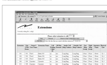
The Extensions screen appears as follows:
View, add, edit, or remove an extension number associated with an inside, outside, or public
address (paging) line
To view, add, edit, or remove an extension:
1. From the AdminTool menu, click on Edit Configuration.
2. If the only file listed is “config”, create an editable file per the instructions in “Creating an editable con-figuration” on page 34.
3. Click on the configuration file you want to edit, then click on Edit Selected File. This will bring up the Edit Configuration menu.
5. Select the extension you want to edit, then click Edit to edit the extension’s parameters, or Remove to remove it. Alternately, to add a new extension, select the line you want associated with a new extension, then click Add new.
6. If editing or creating an extension, review/change the parameters for the extension, then click Keep changes and return.
7. Continue adding, editing, or removing extensions until you are satisfied with the information displayed in the Extensions page.
8. SAVE YOUR EDITS! If you are done editing the configuration, work your way back to the Edit Configura-tion menu and click on Save there, entering a file name in the Save file as box (the file name can be the same as the file you just edited). After entering a file name, click on Save, return to the AdminTool menu. You will also need to schedule your altered configuration file to be activated as outlined in “Acti-vating a particular configuration file” on page 85.
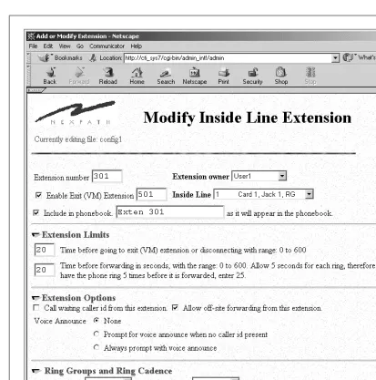
Inside Line Extensions
Parameters for inside line extensions are administered using the Edit Configuration -> Extensions web page from AdminToolTM. This page displays a summary table of the inside and outside line extensions cur-rently defined in this configuration file. An individual extension can be edited by selecting the extension number in the selector box beside the legend “Please select extension to edit”, then clicking on the Edit but-ton. New extensions can be added by selecting the physical line number in the selector box along side this legend, and clicking the button Add New.
Creating more than one extension per physical inside line
When configuring your system, an important feature of the NexPath Telephony Server to remember is that you can assign more than one extension to a given physical line. This allows you to have two people share one phone, or assign one person more than one extension. You can then control how the phone rings depend-ing on which extension is dialed by assigndepend-ing different rdepend-ing cadences to the different extensions.