V-1109RTHF NINE ZONE PAGE CONTROL
13
0
0
Full text
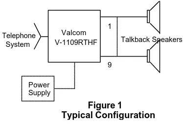
(2) Remember when working with telephone equipment that BATTERY is NEGATIVE and GROUND is POSITIVE.. Numbering Plan The dialing codes are 1-9 and 0 for all call.. Additional Materials Required At the time of installation, the installer should provide the following materials:. DESIGN. •. The V-1109RTHF is designed to work with the following:. • • •. Telephone System Requirements. -24VDC power supply (if existing supply is not adequate) 66 type connecting block 25 pair cable with a female amphenol connector on one end Twisted pair cross-connect wire. PABX - Loop start trunk position. ELECTRONIC KEY SYSTEM - C.O. line button equipped with trunk card.. Dimensions/Weight • • •. 1A2 KEY SYSTEM - C.O. line button on key telephones. NOTE: A 400 type line card is not used for this arrangement.. 7.10" H x 5.90" W x 2.10" D (18.03cm H x 14.99cm W x 5.33cm D) 2.7 lbs. (1.22 kg). The V-1109RTHF has background music inputs and is capable of switching the music. Refer to the Section titled "Music Connections" for music set up and connections.. Electrical Characteristics TABLE 1 Parameters Input impedance Tip and Ring Max cable length to talkback speaker Dial Pulses. Tone Signals Frequency Bandwidth Twist Detect Interdigital Time Environmental Temperature Humidity. Working Limits 600 Ohms 800 feet audio 8-12pps 60-40 break ratio +/- 10% Industry Standard. Telephone System. Valcom V-1109RTHF. 1 Talkback Speakers. 9 Power Supply. Figure 1 Typical Configuration. 3% 6dB 40ms 40ms. Equipment A complete 9 Zone Handsfree Talkback Paging System using the V-1109RTHF will be made up of the following: • PABX loop start trunk position, E-Key C.O. line button or 1A2 line key • V-1109RTHF 9 Zone Talkback Control Unit • Valcom 45 Ohm Talkback speakers • -24VDC power supply (talk and signal battery). 0 to +50°C 0 to 85% Non-precipitating. Power Requirements The Valcom V-1109RTHF requires -24VDC talk battery and -24VDC signal battery. The current consumption and voltage range is shown in Table 2 below. TABLE 2 Talk Battery -21.5 to -26VDC 60mA Signal Battery -21.5 to -25VDC 250mA Lamp Battery 9 to 11VAC 45mA/Lamp. INSTALLATION This section covers the installation procedures for the Valcom V-1109RTHF only. Consult other equipment instructions if additional equipment is used. 2.
(3) of a 1A2 Key Telephone by making the following connections (a 400 type line card is not needed in this application):. Precautions All precautions have been taken at the factory to insure that the equipment functions properly. To insure proper operation and to prevent equipment damage, please observe the following: •. Unplug the power supply before making any connections to the control unit.. •. Do not locate the control unit closer than 18 inches or further than five feet from the power supply. Do not use a lamp tester to check signals, use a voltmeter. A lamp tester when first applies is a short circuit to electronic circuits. Do not apply power to the control unit until all connections have been checked.. • •. •. W/BL, BL/W of V-1109RTHF to spare button Tip and Ring. Refer to Figure 4 for connections. • O/W to Lamp Lead of spare button for lamp connections. Refer to Figure 4 for connections. NOTE: For Meet Me Page on 1A2, connect A-Leads from spare button using 10K Ohm resistors in series with each A-Lead. The other side of resistors are connected to the BK/G (inhibit) of V-1109RTHF. Refer to Figure 6 for connections.. Power Connections • • •. Mounting. • •. Mount the unit in a vacant space in an equipment cabinet, rack or key system cabinet, allowing enough room at the rear of the unit to plug in an amphenol connector. Mount a 66B type punchdown block near the unit and label it per Figure 2.. The V-1109RTHF is designed to use -24VDC battery Connect the V/BR lead to Talk Ground Connect the BR/V lead to Talk Battery (-24VDC filtered). Connect the V/S lead to Signal Ground Connect the S/V lead to Signal Battery (-24VDC unfiltered). NOTE: When the V-1109RTHF is connected to a 1A2 Key System, connect W/O to 10VAC lamp battery. Refer to Figure 5 for connections.. Cabling A 25 pair cable with a female connector should be ran from the unit to the connection block. The cable should be terminated on the connection block in standard color code order. Verify that the connections are correct prior to plugging the other end of the cable into the V-1109RTHF Page Unit.. NOTE: When the V-1109RTHF is connected to a Key System power supply, all grounds should be common and connect to an earth ground, i.e., cold water pipe.. Speaker Connections The output for paging zones start at the BK/BR pair (zone 1) through the V/O pair (zone 9). Refer to Figure 4 for typical speaker connections using Valcom 45 Ohm Talkback speakers. No more than two 45 Ohm Talkback speakers may be connected to a zone.. Connections to PABX System The V-1109RTHF may be accessed by connecting the W/BL and BL/W to the Tip and Ring, respectively, of a Loop Start Trunk Circuit. Refer to Figure 3 for connections.. NOTE: All speakers should be connected with twisted pair, including cross-connections.. Connections to Electronic Key Systems. Music Connections. The V-1109RTHF may be accessed by a C.O. line position of an Electronic Key System by connecting the W/BL, BL/W of the V-1109RTHF to a spare line position of the Electronic Key. This line position must be equipped with a trunk card. Refer to Figure 3 for connections.. The output of a tuner or receiver may be connected to the V/G pair of the V-1109RTHF to provide system-wide background music. NOTE: A low level (0.25vrms) 8 to 600 Ohm source should be used. Do not connect the output of a high power amplifier to this input.. Connections to 1A2 Key System The V-1109RTHF may be connected to a spare button 3.
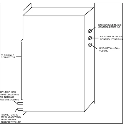
(4) Page and Music Level Set-up The V-1109RTHF has volume controls for the following functions: • Speaker to phone • Phone to speaker • All Call master control • Background music input control Zones 1-5 • Background music input control Zones 6-9. BACKGROUND MUSIC CONTROL ZONES 1-5. BACKGROUND MUSIC CONTROL ZONES 6-9. ONE-WAY ALL CALL VOLUME 50 PIN MALE CONNECTOR. Refer to Figure 7 for volume control locations.. Control Set-Up: 1. Set-up Talkback Controls: (a) The phone to speaker level should be at a normal listening level.. SPK-TO-PHONE TURN CLOCKWISE TO INCREASE RECEIVE VOLUME. PHONE-TO-SPK TURN CLOCKWISE TO INCREASE TRANSMIT VOLUME. Figure 7 - User Control Locations. OPERATION General Description. (b). Speaker to phone level: This is the most critical level; set the volume at the lowest practical level (it is better to set it too low, than too high). 2. All Call Level: The All call level should be set to produce the same audio level as the phone to speaker page control. 3. Background Music Levels: There are two volume controls provided for background music adjustments: Zones 1-5 and Zones 6-9.. To make a voice page, go off-hook and dial the number of the desired zone or station. Dial tone will be broken after the first number is dialed. A one second ringback tone will indicate that the called zone is being signaled. After the tone, proceed with the page. If using talkback speakers, the called party may answer handsfree. If speaker cancel is wired when called party goes off hook, speaker will be turned off. Personal signaling: When initiating a call, depress the "*" and then the station number. A double tone will be sent to the called speaker. No voice announce or talkback will be possible.. It is important that the two background music controls be used to set the music levels in the system. Adjust these controls after all other system volume levels have been set.. To dial a new number (tone dial only), depress the "#" button. The speaker for the first number will be disconnected and dial tone returned to calling party. Dial new number and page.. Repeat Alert Tone. NOTE: If "#" is depressed after the speakers have been inhibited, additional numbers may still be dialed. A tone will signal the called party but no voice announce or talkback will be possible.. A wire jumper controls the 15 seconds alert tone. The repeat alert tone is disabled when the jumper is in place and is enabled by cutting or removing the jumper.. User Instructions In order to achieve maximum performance from this system, the user should receive the following operating instructions. A.. B.. 4. The calling party should speak directly into telephone mouthpiece and avoid speaking too softly. The called party must wait (approximately 1/2 second) before responding to the calling party..
(5) and lamp battery to the telephone set. The logic circuit receives dialing information and operates relays and circuitry to supply splash tone and voice connection to the station selected. On 1A2 systems, when the called or any other party goes off-hook on ICM path, the presence of two resistance ground cancels or turns off speakers (if inhibit resistors are wired). "Handsfree mode" can only be restored by terminating call and redialing station. After paging, the unit automatically disconnects on release of the telephone system.. Circuit Description General Method of Operation: This unit provides dial intercom access provisions to appropriately interface with the telephone system being used. Two-way amplifier conditions the speech from the telephone system Tip and Ring, and provides a low impedance, low level output to the desired speaker via conventional telephone wiring, i.e., house cable or station wire. Detailed Description: When accessing the V-1109RTHF, the telephone system will close the Tip and Ring to form a loop. Loop sense circuitry then operates relay and logic circuits and returns dial tone. Figure 2. 5.
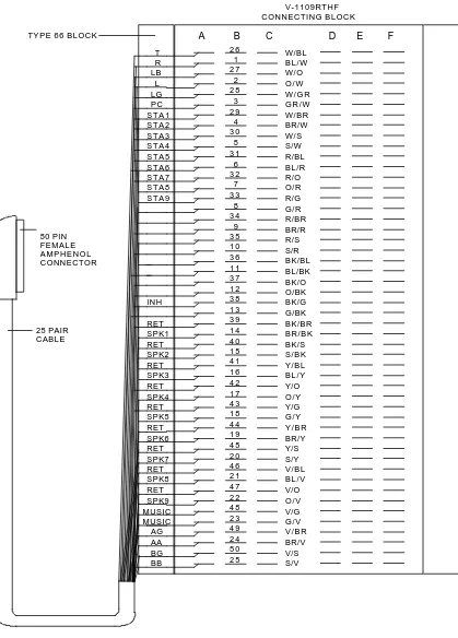
(6) V-1109RTHF CONNECTING BLOCK TYPE 66 BLOCK. A. B 26 1 27 2 28 3 29 4 30 5 31 6 32 7 33 8 34 9 35 10 36 11 37 12 38 13 39 14 40 15 41 16 42 17 43 18 44 19 45 20 46 21 47 22 48 23 49 24 50 25. T R LB L LG PC STA1 STA2 STA3 STA4 STA5 STA6 STA7 STA8 STA9. 50 PIN FEMALE AMPHENOL CONNECTOR. INH. 25 PAIR CABLE. RET SPK1 RET SPK2 RET SPK3 RET SPK4 RET SPK5 RET SPK6 RET SPK7 RET SPK8 RET SPK9 MUSIC MUSIC AG AA BG BB. Figure 3 6. C. D W/BL BL/W W/O O/W W/GR GR/W W/BR BR/W W/S S/W R/BL BL/R R/O O/R R/G G/R R/BR BR/R R/S S/R BK/BL BL/BK BK/O O/BK BK/G G/BK BK/BR BR/BK BK/S S/BK Y/BL BL/Y Y/O O/Y Y/G G/Y Y/BR BR/Y Y/S S/Y V/BL BL/V V/O O/V V/G G/V V/BR BR/V V/S S/V. E. F.
(7) V-1109RTHF CONNECTING BLOCK PABX LOOP START TRUNK PORT OR E-KEY C.O. BUTTON POSITION. A T R. LED 1. 45 OHM TALKBACK SPEAKER W/OPTIONAL LED. +. LED 9. T R. RET SPK1 RET SPK2. 45 OHM TALKBACK SPEAKER. T R. RET SPK9. AG AB BG BB. COLD WATER PIPE GROUND. B. C. D. E. W/BL BL/W W/O O/W W/GR GR/W W/BR BR/W W/S S/W R/BL BL/R R/O O/R R/G G/R R/BR BR/R R/S S/R BK/BL BL/BK BK/O O/BK BK/G G/BK BK/BR BR/BK BK/S S/BK Y/BL BL/Y Y/O O/Y Y/G G/Y Y/BR BR/Y Y/S S/Y V/BL BL/V V/O O/V V/G G/V V/BR BR/V V/S S/V. NOTE: IF USING KEY SYSTEM POWER SUPPLY, CONNECT AG, AB, BG, & BB V-1109RTHF TERMINALS TO CORRESPONDING POWER SUPPLYTERMINALS VALCOM VP-624 B POWER SUPPLY. ELECTRICAL DEFINITIONS AG: TALK GROUND (+) AB: -24VDC TALK BATTERY (FILTERED) BG: SIGNAL GROUND (+) BB: -24VDC SIGNAL BATTERY (NON FILTERED). 7. F.
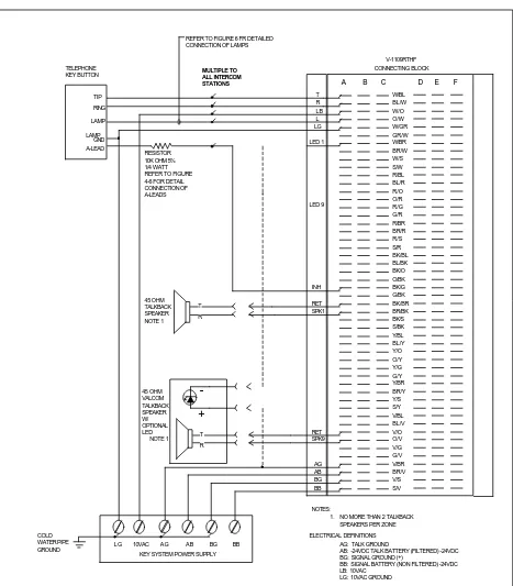
(8) Figure 4. REFER TO FIGURE 6 FR DETAILED CONNECTION OF LAMPS. TELEPHONE KEY BUTTON. V-1109RTHF CONNECTING BLOCK. MULTIPLE TO ALL INTERCOM STATIONS. A T R LB L LG. TIP RING LAMP LAMP GND A-LEAD. LED 1 RESISTOR 10K OHM 5% 1/4 WATT REFER TO FIGURE 4-6 FOR DETAIL CONNECTION OF A-LEADS LED 9. INH 45 OHM TALKBACK SPEAKER NOTE 1. RET SPK1. T R. -. 45 OHM VALCOM TALKBACK SPEAKER W/ OPTIONAL LED NOTE 1. + RET SPK9. T R. AG AB BG BB. B. C. D. E. F. W/BL BL/W W/O O/W W/GR GR/W W/BR BR/W W/S S/W R/BL BL/R R/O O/R R/G G/R R/BR BR/R R/S S/R BK/BL BL/BK BK/O O/BK BK/G G/BK BK/BR BR/BK BK/S S/BK Y/BL BL/Y Y/O O/Y Y/G G/Y Y/BR BR/Y Y/S S/Y V/BL BL/V V/O O/V V/G G/V V/BR BR/V V/S S/V. NOTES: 1. NO MORE THAN 2 TALKBACK SPEAKERS PER ZONE COLD WATER PIPE GROUND. LG. 10VAC. AG. AB. BG. ELECTRICAL DEFINITIONS AG: TALK GROUND AB: -24VDC TALK BATTERY (FILTERED) -24VDC BG: SIGNAL GROUND (+) BB: SIGNAL BATTERY (NON FILTERED) -24VDC LB: 10VAC LG: 10VAC GROUND. BB. KEY SYSTEM POWER SUPPLY. 8.
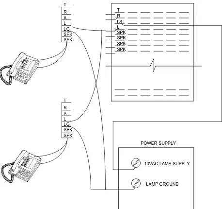
(9) Figure 5. BLOCK DIAGRAM OF LAMP CONNECTIONS. T T R LS L SPK SPK SPK SPK. R A L LG SPK SPK. T R A L LG SPK SPK POWER SUPPLY. 10VAC LAMP SUPPLY. LAMP GROUND. Connect lamp ground leads from telephone ICM buttons to lamp ground terminal on power supply.. 9.
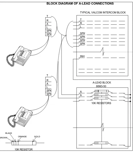
(10) Figure 6 Connect intercom "A" leads to individual rows on left side of split 66 block. Punch down 10K resistors across center of block. Strap individual rows together on right side of block and jumper to inhibit lead of Valcom ICM.. BLOCK DIAGRAM OF A-LEAD CONNECTIONS TYPICAL VALCOM INTERCOM BLOCK T T R L. R A L SPK SPK. SPK SPK SPK SPK. INH. T R A L SPK SPK. A-LEAD BLOCK 66M3-50 A A 10K RESISTORS. BLACK BROWN. ORANGE. GOLD. 10K RESISTOR. 10.
(11) TECHNICAL ASSISTANCE. Repair and Return. Factory Assistance. Valcom equipment is not field repairable. Valcom maintains service facilities in Roanoke, VA. Should repairs be necessary, attach a tag to the unit clearly stating your company name, address, phone number, contact person and the nature of the problem. Send the unit to: Valcom, Inc. Repair and Return Dept. 5614 Hollins Road Roanoke, VA 24019-5056. When trouble is reported, make certain there are no broken connections leading to the system. The chart below identifies possible problems with solutions. Assistance in troubleshooting is available from the factory. When calling, you should have a VOM and a telephone test set available and be calling from the job site. Call (540) 563-2000 for Technical Support or call (540) 767-1555 for Valcom 24-hour Faxback System or visit our website at http://www.valcom.com.. TROUBLESHOOTING CHART PROBLEMS. PROBABLE CAUSES AND CORRECTIONS. Hum heard at phone. • • • • • • •. No speaker cancel. • • •. Background music distorted. •. No side tone No dial tone No volume to speakers. Check "A" battery connection, polarity and voltage. Check "A" and "B" battery connections, polarity and voltage. Check phone to speaker control. Check * for audio present at tip, ring input (W/BL, BL/W pair). Check * for audio at signaled speaker pair at 66B block. Check * for audio at input of speaker. Possible magnetic interference from power supply. Relocate unit and cables at least 18" away from power supply. Check for noisy "A" battery. Verify twisted pairs are being used for speaker connections. Verify ground present at phone side of at least (2) 10K Ohm resistors. Refer to Figure 6. NOTE: Do not apply ground directly to inhibit input. Music source level too high. Refer to "Music Setup Section".. VALCOM LIMITED WARRANTY Valcom, Inc. warrants its products to be free from defects in materials and workmanship under conditions of normal use and service for a period of one year from the date of shipment. The obligation under this warranty shall be limited to the replacement, repair or refund of any such defective device within the warranty period, provided that: 1. 2. 3. 4. 5.. inspection by Valcom, Inc. indicates the validity of the claim; the defect is not the result of damage, misuse or negligence after the original shipment; the product has not been altered in any way or repaired by others and that factory sealed units are unopened (a service charge plus parts and labor will be applied to units defaced or physically damaged); freight charges for the return of products to Valcom are prepaid; all units ‘out of warranty’ are subject to a service charge. The service charge will cover minor repairs (major repairs will be subject to additional charges for parts and labor).. This warranty is in lieu of and excludes all other warranties, expressed or implied, and in no event shall Valcom, Inc. be liable for any anticipated profits, consequential damages, loss of time or other losses incurred by the buyer in connection with the purchase, operation or use of the product. This warranty specifically excludes damage incurred in shipment. In the event a product is received in damaged condition, the carrier should be notified immediately. Claims for such damage should be filed with the carrier involved in accordance with the F.O.B. point. Headquarters: In Canada Valcom, Inc. CMX Corporation 5614 Hollins Road 35 Van Kirk Drive #11 and 12 Roanoke, VA 24019-5056 Brampton, Ontario L7A 1A5 Phone: (540) 563-2000 Phone: (905) 456-1072. 11.
(12) FAX: (540) 362-9800. FAX: (905) 456-2269. 12.
(13) K0. A GROUND A BATTERY. BATTERY FEED. TIP. K1 MICROPROCESSOR. RING K10. K1 RET 1. INHIBIT PAGE CONTROL. TONE DECODER. TALKBACK AMPLIFIER. B BATTERY. K3. ALL CALL CONTROL. K4. POWER SUPPLY. SPK 3 RET 4. K5. 1-5. LED 2. SPK 2 RET 3. K0 LED 1. SPK 1 RET 2. K10. LAMP SUPPLY LAMP B GROUND. K2. LED CONTROL. K0. LED 9. RET 5. AMP K6. 6-9. SPK 4. SPK 5 RET 6. AMP K7. SPK 6 RET 7. MUSIC IN MUSIC IN. K8. MUSIC CONTROL. SPK 7 RET 8. K9. SPK 8 RET 9. SIMPLIFIED SCHEMATIC V-1109RTHF. 13. SPK 9.
(14)
Figure
+3
Related documents
Four root canal sealers were used in this study,(i) an epoxy resin based sealer, AH plus ( Dentsply International Inc, York, PA), (ii) Polymethacrylate resin based sealer,
We conclude the chapter in Section 3.5 by describing the enumeration of the elements in a Tamari congruence class, given any element in the class, and by using a new quantity called
The present study will analyze voltage produced from tropical mangrove forest sediments using earthen pot as cheap proton exchange membrane and by using various cheap cathode
Abstract : The aim of this research is to develop an in-process monitoring system for identification of the states of continuous chip, broken chip and chatter,
In the recipient cell, Erf can promote both generalized plasmid transduction (which requires the circularization of plasmids transduced as linear multimers) and
Exploring Nexus between Urbanization Growth and Environment: with Reference to South Asian Countries
The present research is purely analytical type of research which exclusively relies on secondary data. The necessary data has been collected from the report of the World Bank.
Previous work has demonstrated that opl yeast strains rapidly become inviable when mtDNA is lost (KOVA- COVA et al. As shown in Figure 1, the loss of mtDNA as
Of course there would also be a corresponding proportion of undetected fractionals in the X-ray series, but if we allowed for them, the total fractionals in the X-ray
