A Control Strategy for Distributed Static Compensators
Datla V Praveen & R.Chander
1M.Tech student, PE, Chaitanya Institute of Technology and Science,
Telangana,India e-mail: [email protected]
2Research Scholar Department of Electrical Engineering University College of Engineering (A) Osmania
University,Hyderabad Telangana,India
e-mail: [email protected]
ABSTRACT: Maximum Ac loads consumes reactive power, it leads to terrible power quality in power process. The DSTATCOM is actually a compensating unit that is used to regulate the flow of reactive energy in the distribution systems.This brand new balance tactic takes into consideration the operating VAr boundaries of that reactive flow in figuring out the steady-state output of the DSTATCOM. The brand new control strategy applies a gradual reset regulator (SRR) to gradually bias the VAr set point of the DSTATCOM master controller to keep its steady-state output within a target bandwidth. The operating result maintains an ideal VAr reserve amount from the DSTATCOM for powerful events in the product. This paper also presents a brand new algorithm to compute the operating constraints of the SRR which mirror the VAr flow at the nearby or even remote point in the transmission structure and the allowable VAr thresholds for that flow. These allowable thresholds could be used to the full extent to bring down the steady-state output of the DSTATCOM, maximize its VAr reserve for powerful events and lower equipment and connected method operating losses.
KEYWORDS: Reactive power compensation, DSTATCOM, dqmodel, power control and power quality.
I. INTRODUCTION
In the early days of power transmission in the late 19th century problems like voltage deviation during load changes and power transfer limitation were observed due to reactive power unbalances. Most of the AC loads are consuming reactive power due to presence of reactance. Heavy consumption of
reactive power causes poor voltage quality. Today these Problems have even higher impact on reliable and secure power supply in the world of Globalization and Privatization of electrical systems and energy transfer. The development in fast and reliable semiconductors devices (GTO and IGBT) allowed new power electronic Configurations to be introduced to the tasks of power Transmission and load flow control. The FACTS devices offer a fast and reliable control over the transmission parameters, i.e. Voltage, line impedance, and phase angle between the sending end voltage and receiving end voltage. On the other hand the custom power is for low voltage distribution, and improving the poor quality and reliability of supply affecting sensitive loads. Custom power devices are very similar to the FACTS. Most widely known custom power devices are DSTATCOM, UPQC, DVR among them DSTATCOM is very well known and can provide cost effective solution for the compensation of reactive power and unbalance loading in distribution system.
momentary interruptions. The dynamic performance is analyzed and verified through simulation. It is a custom power device which is gaining a fast publicity during these days due to its exceptional features like it provides fast response, suitable for dynamic load response or voltage regulation and automation needs, Both leading and lagging VARS can be provided, to correct voltage surges or sags caused by reactive power demands DSTATCOM can be applied on wide range of distribution and transmission voltage, overload capability of this provides reserve energy for transients. The causes of power quality problems are generally complex and difficult to detect. Technically speaking, the ideal AC line supply by the utility system should be a pure sine wave of fundamental frequency (50/60Hz).Different power quality problems, their characterization methods and possible causes are discussed above and which are responsible for the lack of quality power which affects the customer in many ways. We can therefore conclude that the lack of quality power can cause loss of production, damage of equipment or appliances or can even be detrimental to human health. It is therefore imperative that a high standard of power quality is maintained. This project demonstrates that the power electronic based power conditioning using custom power devices like DSTATCOM can be effectively utilized to improve the quality of power supplied to the customers.
In practice, the operating VAr limits for local or remote locations in the transmission system may allow some tolerance around the target VAr flow level. This tolerance can be used to lower the steady-state output of the DSTATCOM which is controlling that VAr flow and, hence, relieve the VAr burden on the equipment in the steady-state condition and maximize the VAr reserve for dynamic events. For instance, some engineering projects were designed to run at a low steady-state output of the DSTATCOM to maintain the dynamic VAr reserve to be 90% or more of the equipment MVAr rating to support voltage stability during contingency events. In addition, lowering the steady-state output of the DSTATCOM can reduce the operating losses of the DSTATCOM and associated equipment, such as transformers, and, hence, prolong the life of the
equipment. All of these potential benefits can be realized in the application of the SRR when operating in the -control mode. The combined control system slowly drives the DSTATCOM output toward a low target value within several minutes after a system change (that results in high VAr output of the DSTATCOM), while still observing required operating parameters. The following sections focus on modeling the DSTATCOM master controller with the -control mode, the new control strategy, and algorithm for calculating the SRR operation constraints, implementation and simulations, and case studies.
II. NEW CONTROL STRATEGY AND
ALGORITHM
Fig. 1. Schematic diagram of one device in a DSTATCOM system
For illustrative purposes, a sample simulation is plotted in Fig. 2 to show the DSTATCOM reactive output (red line) versus time that starts with a small value and then increases very fast following a contingency event at 1 s,and then decreases to a new lower setpoint when three capacitor banks (green line) are switched in with a delay time of 10 s.
Fig. 2. Simulation plot of the DSTATCOM control and coordination with switchable capacitor banks
(red DSTATCOM output; green capacitor bank output).
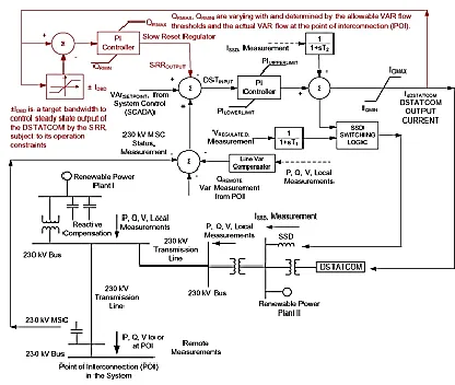
Fig. 3. DSTATCOM master controller, slow reset regulator, and interface with a transmission system
B. DSTATCOM Master Controller With the-Control Mode
control and information acquistion (SCADA) structure by the method operator to complement the VAr flow goal at the POI. For instance, some utilities require that goal to be an extremely small worth, that's, the VAr flow interchange with the system at the POI is actually managed to always be close to 0. Other utilities allow this goal to be managed within the VAr flow thresholds that are additionally settable as well as adaptable via SCADA by the method operator.
Reactive Power in Operations
Reactive power affects power system operation in numerous ways:
1 Loads consume reactive power, so this must be provided by some source.
2 The delivery system (transmission lines and transformers) consumes reactive power, so this must be provided by some source (even if the loads do not consume reactive power). Note however that all transmission lines do provide some reactive power from their shunt line charging which offsets their consumption of reactive power in their series line losses.
3 The flow of reactive power from the supplies to the sinks causes additional heating of the lines and voltage drops in the network.
4 The generation of reactive power can limit the generation of real power. So, one primary dilemma with reactive power is that a sufficient quantity of it is needed to provide the loads and losses in the network, but having too much reactive power flowing around in the network causes excess heating and undesirable voltage drops. The normal answer to this dilemma is to provide reactive power sources exactly at the location where the reactive power is consumed. And, since strictly speaking it does not take any "fuel" to provide reactive power, it should be possible to distribute reactive power sources (such as capacitors) all around the network to avoid the problem of heating the conductors and causing voltage drops. Unfortunately, this is not practical in the extreme since there are literally millions of lines and loads connected to the grid and so this would require millions of reactive power sources - all controlled to provide exactly the right amount of
reactive power at the right time - every second of every day. The best we can do in most cases is work with some type of aggregation of load (say at the feeder leaving a substation) and at terminals of major lines and transformers. This also brings up the issue of the difference between power factor control (trying to exactly provide the right amount of reactive power needed to equal that which is consumed) and voltage control (trying to keep voltage levels at exactly the right level no matter how much reactive power it takes). Reactive power is both the problem and the solution to network voltage control.
III. SIMULATION AND RESULTS
In this work, the performance of VSC based power devices acting as a voltage controller is investigated. Moreover, it is assumed that the converter is directly controlled (i.e., both the angular position and the magnitude of the output voltage are controllable by appropriate on/off signals) for this it requires measurement of the rms voltage and current at the load point.
Fig.4 load voltage, load current & load voltage magnitude respectively with Inductive load in the
Fig.5 load voltage, load current & load voltage magnitude respectively with Capacitive load in the
uncompensated line
Fig.6 Load voltage, load current & load voltage magnitude respectively with Inductive load in the
compensated line
IV. CONCLUSION
This paper given a brand new control method which applies a slow reset regulator (SRR) in the DSTATCOM master control system running with the -control mode along with a completely new algorithm for calculating the SRR functioning constraints which reflect the particular VAr flow at a local or even remote thing in a transmission process and also the thresholds for that flow. The brand new management strategy and calculation algorithm have been applied in a powerful simulation type of the DSTATCOM operating in the -control method in a commonly used power system simulator. The implemented control
strategy as well as calculation algorithm were simulated and used in a true transmission system representing an engineering project which contains a DSTATCOM-based reactive compensation program as well as a number of sustainable powerplants in which the -control mode was utilized to manage the transmission VAr flow at a remote thing in the transmission phone.
REFERENCES
[1] R. M. Mathur and R. K. Varma, Thyristor-Based FACTS Controllers for Eletrical Transmission Systems. Hoboken, NJ, USA: Wiley, 2002, IEEE.
[2] N. G. Hingorani and L. Gyugyi, Understanding FACTS: Concepts and Technology of Flexible AC Transmission Systems. Piscataway, NJ, USA: IEEE, 2000.
[3] WECC Static VAr Compensator Task Force, “Generic static VAr system models for the Western Electricity Coordinating Council,” Rep. no. 4/18/11, Apr. 18, 2011. [Online]. Available: https://www.wecc.biz/Reliability/GenericStaticVarSy stemModelsforWECC.pdf
[4] Y. Xu and F. Li, “Adaptive PI control of STATCOM for voltage regulation,” IEEE Trans. Power Del., vol. 29, no. 3, pp. 1002–1011, Jun. 2014.
[5] S. Kincic, X. (G.) T. Wan, D. T. McGillis, A. Chandra, B.-T. Ooi, F. D. Galiana, and G. Joos, “Voltage support by distributed Static VAr Systems (SVS),” IEEE Trans. Power Del., vol. 20, no. 2, pt. 2, pp. 1541–1549, Apr. 2005.
[6] Jain, K. Joshi, A. Behal, and N. Mohan, “Voltage regulation with STATCOMs: Modeling, control and results,” IEEE Trans. Power Del., vol. 21, no. 2, pp. 726–735, Apr. 2006.
[7] D. Soto and R. Pena, “Nonlinear control strategies for cascaded multilevel STATCOMs,” IEEE Trans. Power Del., vol. 19, no. 4, pp. 1919–1927, Oct. 2004.
IEEE Trans. Power Del., vol. 13, no. 2, pp. 538–544, Apr. 1998.
[9] A. H. Norouzi and A. M. Sharaf, “Two control schemes to enhance the dynamic performance of the STATCOM and SSSC,” IEEE Trans. Power Del., vol. 20, no. 1, pp. 435–442, Jan. 2005.
[10] V. Spitsa, A. Alexandrovitz, and E. Zeheb, “Design of a robust state feedback controller for a STATCOM using a zero set concept,” IEEE Trans. Power Del. , vol. 25, no. 1, pp. 456–467, Jan. 2010.
[11] L. Wang and D. Truong, “Dynamic stability improvement of four parallel-operated PMSG-based offshore wind turbine generators fed to a power system using a STATCOM,” IEEE Trans. Power Del., vol. 28, no. 1, pp. 111–119, Jan. 2013.
[12] C. Wang, X. Yin, Z. Zhang, and M. Wen, “A novel compensation technology of static synchronous compensator integrated with distribution transformer,” IEEE Trans. Power Del., vol. 28, no. 2, pp. 1032–1039, Apr. 2013.
[13] J. M. Bloemink and T. C. Green, “Benefits of distribution-level power electronics for supporting distributed generation growth,” IEEE Trans. Power Del., vol. 28, no. 2, pp. 911–919, Apr. 2013.
[14] T. Aziz, M. J. Hossain, T. K. Saha, and N. Mithulananthan, “VAR planning with tuning of STATCOM in a DG integrated industrial system,” IEEE Trans. Power Del., vol. 28, no. 2, pp. 875–885, Apr. 2013.
[15] S. Du and J. Liu, “A study on dc voltage control for chopper-cell-based modular multilevel converters in d-STATCOM application,” IEEE Trans. Power Del., vol. 28, no. 4, pp. 2030–2038, Oct. 2013
Authors: