Departement de g ´enie m ´ecanique (DGM) ENS Cachan, 61 avenue du Pr ´esident Wilson, 94235 Cachan Cedex, France
2 Blast Impact and Survivability Research Unit (BISRU), Department of Mechanical Engineering,
University of Cape Town, Private bag X3, Rondebosch 7701, South Africa
3 L.M.T. Cachan, 61 avenue du Pr ´esident Wilson, 94235 Cachan Cedex, France
Abstract. Knowledge of soft porous materials, such as cancellous bone, under dynamic loading requires accurate descriptions of high-rate mechanical responses. A novel modification of the standard Split Hopkinson Pressure Bar (SHPB) technique, that makes dynamic specimen recovery possible, is presented. Two impedance matched tubes, operating in tandem, are concentrically aligned with the incidence bar and placed in contact with a collar at the striker end. The collar transfers half of the incidence stress wave and most (>90%) of the reflected stress wave into the concentric tubes. In other words, the tubes act as sequential momentum traps and provide a single specimen loading event of predefined intensity and duration. This approach allows for routine testing without the need for initial “gap setting” ,i.e.an accurate initial offset of the momentum trap with respect to the collar. Experimental results from a series of tests on cancellous bovine bone are presented. Furthermore, results from a microstructural investigation of the recovered specimens are presented and compared with quasi-statically loaded specimens.
1 Introduction
1.1 Background
Automobile accidents and sporting injuries may lead to os-seous fractures. These fractures are due to the impact load-ing of the bones. A better understandload-ing of this fracture mechanisms will aid in the design of protective features that will guard against fracture under these loading condi-tions. Bone is generally divided into two micro-structural types namely cortical and cancellous bone. Cortical bone is a compact type of bone and is denser than cancellous. Cortical bone accounts for 80 % of the skeletal mass in the human body [1]. Cancellous bone, also called trabecular or spongy bone, has a porous structure that protects the bone marrow, acts as a core material to support the shape of thin layers of cortical bone and assist in transfering joint forces to the thick load bearing cortical bone layers.
1.2 Momentum trapping and specimen recovery techniques
The Hopkinson Bar was introduced in 1914 by Hopkinson [2], where the shapes of impact-induced pulses passing through steel rods were measured. Kolsky [3] further developed the Split-Hopkinson Pressure Bar (SHPB) by placing a specimen between two bars. The SHPB has become the standard apparatus in the testing of materials in tension, compression and torsion at high strain rates (102–104s−1) [4]. The standard experimental configuration of the SHPB cannot be employed to investigate the high
ae-mail:marianne.prot@ens-cachan.fr be-mail:trevor.cloete@uct.ac.za ce-mail:pattofat@lmt.ens-cachan.fr
strain rate effects on soft material with specimen recovery as the specimen is subjected to repeated loading pulses due to wave reflections at the bar ends.
Nemat-Nasser et al.[5] developed a momentum trap-ping technique in order to subject a specimen to a single stress pulse. They used co-axially mounted tubes that were impedance matched to the bars to captured most (>90%) of the momentum in the reflected pulse. This was sufficient to prevent any significant reloading of the tensile specimens that were screwed into the bars.
Chen & Song [6] employed a similar setup (see Figure 1), where the impedance match tube was replaced with a large co-axial mass (i.e. the ’Rigid Mass’ Figure 1). In this case, the returning reflected pulse would cause a flange, screwed to the end of the bar, to interact with the large mass and produce a tensile pulse that would run up the bar toward the specimen. This secondary tensile pulse causes the end face of the input bar to pull away from the specimen, thus preventing any further loading.
1.3 Limitations of current techniques
Both the methods of Nemat-Nasseret al.and Chen & Song reply on an initial gap to be left between the transfer flange and the momentum trap or reaction mass, i.e. they are initally uncoupled. The intention is that this gap will be closed during the striker impact phase. The result is that when the reflected wave returns it will be captured by a momentum trap (or reversed by a reaction mass) such that the specimen will not experience subsequent loading. This technique requires a high level of accuracy in the setting of the gap and control of the striker speed, both of which are difficult to maintain during routine testing. The aim of this paper is to present a technique that accomplishes near
Fig. 1.A schematic of SHPB with momentum trap [6].
Fig. 2.Input bar system with Fla.1“opened” for the picture and half supports.
complete momentum trapping at any striker impact speed without the need for intricate gap setting.
2 Experimental technique
2.1 Concept
The apparatus (Figure 2) consists of two impedance matched tubes, operating in tandem. They are concentri-cally aligned with the incidence bar and placed in contact with a collar at the striker end. Upon impact of the striker, compression waves are set up in both the input bar and the inner tube (M.T.1) through a flange (Fla1). Since the inner (M.T.1) and outer (M.T.2) tubes are impedance matched, the compression wave inM.T.1will be transfered toM.T.2 without reflection, though a second flange (Fla2). This will cause M.T.2 to move away while M.T.1 will remain in contact with the input bar flange (Fla1). The result of this is that when a reflected pulse returns in the input bar, it will be transfered, without reflection, throughFla1intoM.T.1, after which it will seperate from Fla1. In other words, the tubes act as sequential momentum traps and provide a single specimen loading event of predefined intensity and duration. This approach allows for routine momentum trapping without the need for accurate initial gap setting. A schematic diagram of the apparatus is shown in Figure 4. A typical result for testing the input bar is shown in Figure 3. The dark line is the incidence and 1st reflection signal, while the grey line is an inversion of the the 1st and 2nd reflection that has been time shifted for comparison. In other words it shows that the incidence and 1st reflection are identical, as expected, but that the majority of the momentum has been removed from the 2nd reflection. The tandem momentum trap concept was implemented using standard size 6000 series Al tubing. This resulted
Fig. 3.Signal history : comparison of the reflected wave and the peaks times.
in relatively large annular clearances between bar and tubes which necessitated the use of broad flanges. This introduced a small, but noticable, amount of compliance that had an adverse affect on the performance of the momentum trap. The performance can be improved by using a tightly nested set of tubes.
A calculation of the influence of residual stress peaks in the 2nd reflection on the total displacement of the bar shows that they contribute no more than 3% of the total displacement. A high speed camera was used to film several tests, the data was used to investigate a single loading event and determine how the specimen fails. The footage shows that the specimen is already falling out from between the bars when the residual 2nd reflection pulse arrives at the specimen interface. The footage confirms that the specimen is only loaded once to a predefined intensity and duration.
Despite the slightly sub-optimal performance, the tan-dem momentum trap suceeded in the aim of allowing dy-namic recovery tests to be performed, as will be discussed in the following sections.
2.2 Material and methods
The material and geometry specifications of the experi-mental setup are given in Table 1. A magnesium output bar was used to increase the intensity of the output signal and each experiment was checked for equilibrium.
Fig. 4.Schematic representation (not to scale) of the bar concept.
Table 1.Properties of the apparatus.
Properties Al. M.T.1 M.T.2 Mg. Input Bar Output bar
Length (L.) (mm) 3662 1400 1350 1998
Inner Diameter (mm) N/A 23 31.6 N/A Outside Diameter (mm) 19.1 30.1 36.9 19.84
Weight (kg) 2.9 1.32 0.88 1.12 Density (g/cm3) 2.77 2.76 2.76 1.82
Length (from specimen 1818 N/A N/A 197 to gauge) (mm)
Wave Speed (m/s) 5033 5033 5033 4994 Young Modulus (GPa) 70.175 70.175 70.175 45.765
Impedance (kPa.s/m) 13941 13941 13941 9089
With this appartatus, series of experiments were carried out to investigate the response of bovine cancellous bone to different combinations of strain-stress under the same high strain rates that are representative of a real impact in the daily life. The specimen introduced between the input and output bar will be only loaded once to a predetermined intensity and duration.
3 Microstructural investigation of
recovered specimens
3.1 Specimen preparation
Fresh bovine femoral bone were purchased and thoroughly thawed in water before machining. Specimens with a diam-eter and length of 10 mm were machined from the distal sections of fresh bovine femoral bones. These specimen dimensions are typical of that reported in the literature on the high strain rate testing of soft materials [6, 8, 9]. Specimen equilibrium was investigated by comparing the stress histories at the two specimen faces. The measured dynamic Young’s modulus was only considered to be valid if the two stress histories were in agreement. To determine the response of cancellous bone to a variety of strain rates, four sets of experiments were performed at high strain rates and four at low strain rates. To assess the
repeatability of the experiments, three experiments were performed at each of the various strain rates and the results compared. In order to limit the effects of preservation, the specimens were prepared at the latest possible time before experimentation began [10]. During the storage periods bones were kept in water in the freezer and defrosted the day before of testing. For the dynamics tests, the bone was tested immediately after machining.
3.2 Test series parameters
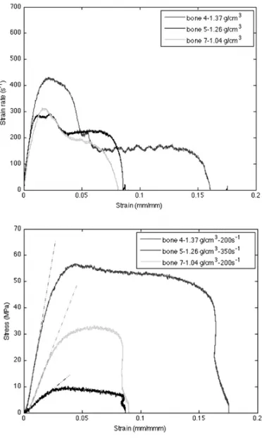
The strain rate versus strain and stress versus strain curves for some specimens are illustrated in Figure 5. The com-pressive strength (σ) and the Young’s modulus (E) increase with density (ρ). This relationship can be described by a power-law function (cf. Figure 6).
The maximum compressive strength and Young’s modulus are plotted as a function of the bone density in Figure 6.
Using a least squares fit to the experimental data the compressive strength and the Young’s modulus can be described by σ = fρα and σ = E0ρβ respectively. The values derived from curve-fitting are presented in the following table:
f(Mpa) α E0(MPa) β
8.51 5.06 340 5.30
In contrast to the compressive stress and Young’s modulus, the results indicate that the dynamic failure strain does not depend on the density and is consistently in the range of 0.3 to 0.4. This observation concurs with that reported reported by Keaveny [11]. The consistent failure strain is also evident in the linear trend between the compressive maximum strength (σ) and Young ˜Os modulus (E), as shown in Figure 7. The relationship can be described byσ=0.025E−0.361.
3.3 Macrostructural results
Fig. 5.Signals of the dynamict tests.
Fig. 6. Influence of the bone density-experimental points and fitted curves.
examining the recovered specimens, it was discovered that crushing of the specimen predominantly occurred on the magnesium side of the SHPB. Furthermore, a repeatable shear angle was observed on the fracture surfaces of the intact portion of the recovered specimens. On three bones the angle of shear is approximatively 25 degrees (Cf. Figure 8).
Fig. 7.Relation between material properties.
Fig. 8. Macrostructure bone failure (right) of the bone 3 in comparison & reference (left).
Fig. 9. Bone crushings (Reference size (left), Dynamic load-ing(middle one), Quasi-static loading (right).
On a fourth specimen, a V-shaped shear fracture is visible. The presence of a V-shaped shear fracture is attributed to the different trabeculae and cortical orienta-tion in the specimen by Van Der Westhuisen [12], who reported that a longitudinal cortical bone breaks with a V-shaped shear fracture across the longitudinal porosity. It was also observed that all the specimens crushed on the upper side during Quasi-Static loading. The bones tested beyond the yield point showed that the cancellous spec-imens break with a similar angle as during the dynamic tests of about 30 degrees. Bone specimens that were not loaded beyond the yield point exhibited bulge deformation (cf. Figure 9).
3.4 Microstructural investigation
Following the specimen sectioning protocol used in pre-vious studies [1, 12], the microstructural investigation of cancellous bone is divided into several steps : embedding specimens in a mounting medium of resin, sectioning of embedded bone with a diamond blade, grinding one surface to affix to a slide, mounting of the specimens on a slide with an epoxy resin, thin and polished slide preparation. Two bones were studied: Bone 3 and Bone A from the dynamics tests.
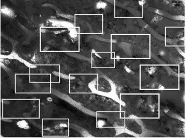
Fig. 10.Several failures in the bone A.
Fig. 11.Failure mechanism in Bone 3.
Fig. 12.Failure mechanism in Bone A.
bone A showed that parallel lines of cracks were ap-parent, implying an incipients shear band formation (cf. Figure 10). Different modes of failure were also observed (cf. Figures 11 & 12).
The macroscopic results are similar with regard to the macroscopic shear angle observed in the spec-imens deformed beyond the yield point. However, the microscopic investigation found that there are distinct differences in terms of the failure mechanism and pattern between static and dynamic loading. The quasi-static damage tended to be localized on the region of shearing, while the dynamic damage appeared to be more diffuse.
3.5 Comparison with quasi-statically loaded specimens These result were compare from the quasi-static result of S.Higgins[1] (cf. Figure 13).
These preliminary results demonstrate the value of being able to recover dynamically deformed specimens
using the tandem momentum trapping system presented in this paper.
4 Conclusion
A novel modification of the standard Split Hopkinson Pressure Bar (SHPB) technique that makes dynamic spec-imen recovery possible, has been presented along with preliminary test results on bovine cancellous bone. The tandem momentum strap concept removes the need for accurate gap-setting and facilitates the measuring of the response of bovine cancellous bone to different combi-nations of strain and stress under the same high strain rates that are representative of a real impact in the daily life. The specimen introduced between the input and out-put bar is only loaded once to a predetermined inten-sity and duration. The results are encouraging and in-dicate that this is a potential technique for conducting recovering tests especially needed for cancellous bone investigations.
Acknowledgements
The authors wish to thank Mr. G. Newins and Mr. C. Nicholas (mechanical workshop, Department of Mechanical Engineering, University of Cape Town) for the machining of the apparatus, Mr C. Harris from the Human Biology department, for the machining of the specimens, Dr A. Chinsamy-Turan, from the zoology department for her advice regarding on the microstructure inves-tigation and the members of the Blast Impact and Survivability Research Unit for their assistance during the project.
References
1. S. Higgins, Strain rate and density dependent behaviour of bovine cancellous bone in compression (Master’s thesis, University of Cape Tow, 2008) 2. B. Hopkinson, Philosophical Transactions of the
Royal Society of London. Series A, Containing Pa-pers of a Mathematical or Physical Character, 1914, 213:437456.
3. H. Kolsky,An Investigation of the Mechanical Proper-ties of Materials at Very High Rates of Loading (Pro-ceedings of the Physical Society, Section B, 1949), 62:676700.
7. A.S. Bowden,Experimental and numerical study on the effect of strain rate to ductile damage (Master’s thesis, University of Cape Town, 2009)
8. D.R. Carter and W.C. Hayes, Reprint in The Journal of Bone and Joint Surgery, 2007.
9. D. L. Kopperdah and T.M. Keaveny, Yield strain behavior of trabecular bone, Elsevier, 1998.
Yeh, Biomechanics of trabecular bone, Biomedical Engineering, 2001.