Drainage and waste disposal
The Building Regulations 2000
H
H1
Foul water drainage
H2
Wastewater treatment systems and cesspools
H3
Rainwater drainage
H4
Building over sewers
H5
Separate systems of drainage
H6
Solid waste storage
APPROVED DOCUMENT
Building Regulations 2000 APPROVED DOCUMENT HDrainage
and waste disposal
edition
Published by NBS, part of RIBA Enterprises Ltd, and available from:
RIBA Bookshops Mail Order
15 Bonhill Street London EC2P 2EA
Telephone orders/General enquiries: 020 7256 7222 Fax orders: 020 7374 2737
Email orders: [email protected] Or order online at:
www.thebuildingregs.com
www.thenbs.com
© Crown copyright 2006
The Approved Documents are published by NBS for the Office of the Deputy Prime Minister. This publication has been approved by Ministers and has official status. Copyright in the contents, the cover, the design and the typographical arrangement of this publication rests with the Crown unless otherwise stated. The contents of this publication may be reproduced free of charge in any format or medium for the purposes of private research and study or for internal circulation within an organisation. This is subject to the contents being reproduced accurately and not in a way that implies official status. Any publisher wishing to reproduce the content of this publication must not use or replicate the ODPM crest or replicate the official version’s style and appearance, including the cover design, and must not present their publication as being an official publication as this may confuse the public. The reproduced material must be acknowledged as Crown Copyright and the title of the publication specified. The Office of the Deputy Prime Minister does not accept any responsibility for the accuracy and comprehensiveness of any other versions.
Any other use of the contents of this publication would require a copyright licence. Please apply for a licence by writing to the Office of Public Sector Information, Information Policy Team, St Clements House, 2-16 Colegate, Norwich NR3 1BQ. Fax 01603 723000 or email [email protected]. Further information can be obtained from www.opsi.gov.uk.
ISBN-10 1 85946 208 1 ISBN-13 978 1 85946 208 9 Stock code 56660
RIBA Bookshops
66 Portland Place, London W1B 1AD. Telephone 020 7256 7222.
113-115 Portland Street, Manchester M1 6DW. Telephone 0161 236 7691.
Birmingham & Midland Institute, Margaret Street, Birmingham B3 3SP. Telephone 0121 233 2321. RSUA, 2 Mount Charles, Belfast BT7 1NZ. Telephone 028 9032 3760.
Renew Rooms, 82 Wood Street, Liverpool L1 4DQ. Telephone 0151 707 4380.
ONLINE
VERSION
ONLINE
VERSION
ONLINE
VERSION
All references to the Building Regulations 2000 (as amended) should be read as references to the Building Regulations 2010.
All references to the Building (Approved Inspectors etc.) Regulations 2000 should be read as references to the Building (Approved Inspectors etc.) Regulations 2010.
There have been no substantive requirements amendments to either set of regulations, but please note the simplification of the definition of ‘room for residential purposes’ in regulation 2 of the Building Regulations 2010. Please also note that L1(c) has now become regulation 40.
The following tables will help you to find the new regulation number for regulations which have been re-numbered in the 2010 Regulations. For any regulation number not included in the tables below, the number of the regulation has not changed.
Amendments to Approved Documents and
Compliance Guides 2010
ONLINE
VERSION
ONLINE
VERSION
ONLINE
VERSION
Building Regulations
Regulation number in Building Regulations 2000 Regulation number in Building Regulations 2010 Regulation number in Building Regulations 2000 Regulation number in Building Regulations 2010 Regulation number in Building Regulations 2000 Regulation number in Building Regulations 2010 2(2A) 2(3) 12(7) 12(8) 20AA 42 2(2B) 2(4) 13(2)(c)(iii) 13(2)(ii) 20B 43 2(2C) 2(5) 13(3) deleted 20C(A1) 44(1) 2(3) deleted 13(5) 13(3) 20C(1) 44(2) 3(1)(g) 3(1)(h) 13(6) 13(4) 20C(2) 44(3) 3(1)(h) 3(1)(g) 13(7) 13(5) 20C(3) 44(4) 4(1A) 4(2) 14(3)(aa) 14(3)(b) 20D 27 4(2) 4(3) 14(3)(b) 14(3)(c) 20E 37 4A 23 14A 15 21(1) 18(1) 4B(1) 22 15 16 21(2) 18(8) 4B(2) deleted 16A 20 21(3) 18(2) 6(1)(cc) 6(1)(d) 16B 38 21(4) 18(3) 6(1)(d) 6(1)(e) 16C 39 21(5) 18(4) 6(1)(e) 6(1)(f) 17A 24 21(6) 18(5) 6(1)(f) 6(1)(g) 17B 25 21(7) 18(6) 6(1)(ff) 6(1)(h) 17C 26 21(8) 18(7) 6(1)(g) 6(1)(i) 17D 28 22 479(1A) 9(2) 17E(4) 29(5) 22B(1)(a) 48(1)(a) 9(2) 9(3) 17E(5) 29(4) 22B(1)(b) 48(1)(b) 9(3) 21(1) 17F 30 22B(1)(c) 48(1)(c) 9(4) 21(2) 17G 31 22B(1)(d) 48(1)(g) 9(5) 21(3) 17H 32 22B(1)(e) 48(1)(d) 9(5A) 21(4) 17I 33 22B(1)(f) 48(1)(i) 9(6) 21(5) 17J 35 22B(1)(g) 48(1)(j) 12(2) 12(1) 17K 36 22B(1)(h) 48(1)(l) 12(2A) 12(2) 18 45 22B(1)(ha) 48(1)(m) 12(4A) 12(5) 19 46 22B(1)(i) 48(1)(n) 12(5) 12(6) 20 19 22B(1)(j) 48(1)(o) 12(6) 12(7) 20A 41 22B(1)(k) 48(1)(h) 22B(1)(ka) 48(1)(k) J2A J3 J6 J7 22B(1)(l) 48(1)(e) J3 J4 L1(c) Regulation 40 22B(1)(m) 48(1)(f) J4 J5 Schedule 2A Schedule 3 22B(2) 48(2) J5 J6 Schedule 2B Schedule 4
ONLINE
VERSION
ONLINE
VERSION
ONLINE
VERSION
Building (Approved Inspectors etc.) Regulations
Regulation number in Building (Approved Inspectors etc.) Regulations 2000 Regulation number in Building (Approved Inspectors etc.) Regulations 2010 Regulation number in Building (Approved Inspectors etc.) Regulations 2000 Regulation number in Building (Approved Inspectors etc.) Regulations 2010 Regulation number in Building (Approved Inspectors etc.) Regulations 2000 Regulation number in Building (Approved Inspectors etc.) Regulations 2010 1 1 and 38 13(1)(d) 12(6)(c) 25(2) 25(3) 3 4 13(2) 12(1) 25(3) 25(4) 4 3 13(3) 12(2) 31A(a) 32(c) 8 10 13(4) 12(3) 31A(b) 32(c) 9 11 13(5) 12(4) 31A(c) 32(e) 10(1) 9(5) 13(6) 12(5) 31A(d) 32(f) 10(2) 9(1) 13A 13 31A(e) 32(h) 10(3) 9(2) 14 14(1) 31A(ea) 32(i) 10(4) 9(3) 15(1) 14(2) 31A(f) 32(j) 10(5) 9(4) 15(2) 14(3) 31A(g) 32(k) 11(1)(a) 8(1)(a) 15(3) 14(4) 31A(h) 32(d) 11(1)(c) 8(1)(b) 16 15 31A(ha) 32(g) 11(2) 8(2) 17 16 31A(i) 32(a) 11A 20(1) 18(1) 17(1) 31A(j) 32(b) 12 20(1) and (3) 18(2) 17(2) and (3) *Sch 3 7A Sch 2 8 12A 20(1) and (5) 18(3) 17(4) Sch 3 8 Sch 2 9 12AA 20(1) 18(4) 17(5) Sch 3 9 Sch 2 10 12B 20(1) 18(5) 17(6) Sch 4 7A Sch 3 8 12C 20(1) and (6) 18(6) 17(7) Sch 4 8 Sch 3 9 12D 20(1) and (2) 19 18 Sch 6 5A Sch 5 6 12E 20(1) and (4) 20 19 Sch 6 6 Sch 6 7 13(1) 12(6) 23A 24 13(1)(b) 12(6)(a) 24 25(1) 13(1)(c) 12(6)(b) 25(1) 25(2)Please note that some of the numbering and cross referencing in the forms in Schedule 1 has changed slightly. *Sch =Schedule
ONLINE
VERSION
ONLINE
VERSION
ONLINE
VERSION
APPROVED DOCUMENTS
The following documents have been approved and issued by the First Secretary of State for the purpose of providing practical guidance with respect to the requirements of the Building Regulations 2000 (as amended).
Approved Document A: Structure
2004 edition incorporating 2004 amendments
Approved Document B: Fire safety
2000 edition incorporating 2000 and 2002 amendments
Approved Document C: Site preparation and resistance to contaminants and moisture
2004 edition
Approved Document D: Toxic substances
1992 edition incorporating 2002 amendments
Approved Document E: Resistance to the passage of sound
2003 edition incorporating 2004 amendments
Approved Document F: Ventilation
2006 edition
Approved Document G: Hygiene
1992 edition incorporating 1992 and 2000 amendments
Approved Document H: Drainage and waste disposal
2002 edition
Approved Document J: Combustion appliances and fuel storage systems
2002 edition
Approved Document J: 2002 Edition: Guidance and Supplementary Information on the UK Implementation of European Standards for Chimneys and Flues
2002 edition
Approved Document K: Protection from falling collision and impact
1998 edition incorporating 2000 amendments
Approved Document L1A: Conservation of fuel and power
New dwellings 2006 edition
Approved Document L1B: Conservation of fuel and power
Existing dwellings 2006 edition
Approved Document L2A: Conservation of fuel and power
New buildings other than dwellings 2006 edition
Approved Document L2B: Conservation of fuel and power
Existing buildings other than dwellings 2006 edition
Approved Document M: Access to and use of buildings
2004 edition
Approved Document N: Glazing – safety in relation to impact, opening and cleaning
1998 edition incorporating 2000 amendments
Approved Document P: Electrical safety – Dwellings
2006 edition
Approved Document to support regulation 7: Materials and workmanship
1992 edition incorporating 2000 amendments
MAIN CHANGES IN THE
2002 EDITION
This edition of the Approved Document H, Drainage and solid waste, replaces the 1992 edition. The main changes are:
H1 Foul drainage
a. Low flush WCs – guidance is provided for the design of sanitary pipework serving such appliances.
b. Condensate from boilers – guidance is provided on disposal of condensate. c. Guidance has been given to clarify that
the requirements of H1 apply to the whole drainage system including associated private sewers.
d. Use of pumping stations – guidance has been added to improve protection of low-lying properties.
e. Protection from rats in drains – the guidance has been modified.
f. Grease separators – guidance is given on their provision in commercial hot food premises.
g. Drain pipe sizes – drains/sewers serving more than 10 dwellings should have a minimum diameter of 150mm.
h. A general requirement of drainage is now included. This was originally the subject of Section 21 of the Building Act 1984.
H2 Wastewater treatment systems
and cesspools
i. Drainage fields from septic tanks – guidance
is provided on design and siting.
j. Reed beds – have been added as a means of secondary treatment.
k. Maintenance information – a notice should be provided in an appropriate place setting out maintenance procedures for non-mains drainage systems.
H3 Rainwater drainage
l. Sustainable rainwater drainage – guidance on the use of infiltration drainage systems is provided.
m. Rainfall intensity – additional guidance is provided.
n. Drainage of certain paved areas for access or waste disposal – these areas should be free draining.
H4 Building over sewers
o. This is a new requirement dealing with situations previously covered by section 18 of the Building Act 1984 (Section 18 is
H5 Separate systems of drainage
p. This new requirement sets out the circumstances where separate systems of drainage are required.
H6 Solid waste storage
(was previously H4)
q. Storage space for dwellings – provides guidance on space for the collection of waste to be recycled.
r. Access to storage areas – guidance is provided on steps and slopes.
ONLINE
VERSION
ONLINE
VERSION
ONLINE
VERSION
Contents
PAGE
Use of guidance 4
The Approved Documents 4
Limitation on requirements 4
Materials and workmanship 4
Technical specifications 4
The Workplace (Health, Safety and Welfare)
Regulations 1992 5
Safe working in drains and sewers 5
Foul water drainage
– The Requirement H1 6
Guidance 6
Performance 6
Introduction to provisions 6
Section 1: Sanitary pipework 7
Traps 7
Branch discharge pipes 7
Discharge stacks 10
Materials for pipes, fittings and joints 11
Workmanship 12
Air tightness 12
Alternative approach 12
Section 2: Foul drainage 13
Outlets 13
Surcharging of drains 13
Layout 13
Special protection – rodent control 14
Protection from settlement 14
Depth of pipe cover 15
Pipe gradients and sizes 15
Pumping installations 16
Materials for pipes and jointing 16
Bedding and backfilling 17
Clearance of blockages 19
Workmanship 21
Testing and inspection 21
Alternative approach 22
Appendix H1-A Additional guidance
for larger buildings 23
Capacity of pipes 23
Traps 23
Branch discharge pipes 23
PAGE
Ventilating stacks 23
Greywater recovery systems 24
Appendix H1-B Repairs, alterations and
discontinued use of drains and sewers 25
Legislation 25
Power to examine and test 25
Power to require repairs 25
Power to repair drains or private sewers 25 Repair, reconstruction or alterations to
underground drains or sewers 25
Sealing or removal of disused drains
or sewers 25
Guidance 26
Repairs and alterations 26
Sealing disused drains 26
Appendix H1-C Adoption of sewers and
connection to public sewers 27
An agreement with the sewerage
undertaker to adopt sewers on completion 27 Requisition of a sewer from the
sewerage undertaker 27
Adoption by the sewerage undertaker at
the request of the owner 27
Adoption by the sewerage undertaker at
its own volition 27
Making connections to public sewers 27
Drains which could be used to drain
other developments 27
Adoption of surface water sewers by
the highway authority 27
Wastewater treatment systems and cesspools – The Requirement H2 29 Guidance 29 Performance 29 Introduction to provisions 30 Options 30 Septic tanks 31 Siting 31
Design and construction 31
Marking 31
Drainage fields and drainage mounds 31
Siting 31 Ground conditions 32
H
ONLINE
VERSION
ONLINE
VERSION
ONLINE
VERSION
PAGE
Design and construction 32
Constructed wetlands/reed beds 33
Marking 35
Packaged treatment works 35
Siting 35
Design and construction 35
Marking 35
Cesspools 35
Siting 35
Design and construction 35
Marking 35
Greywater and rainwater storage tanks 36
Alternative approach 36
Appendix H2-A Maintenance of wastewater treatment systems
and cesspools 37
Legislation 37
Power to examine and test 37
Power in respect of overflowing or leaking
cesspools, septic tanks, etc. 37
Power to require repairs 37
Disused septic tanks, cesspools, etc. 37
Powers of the Environment Agency 37
Guidance on maintenance 37
Septic tanks 37
Drainage fields and mounds 37
Packaged treatment works 37
Constructed wetlands/reed beds 38
Cesspools 38 Rainwater drainage – The Requirement H3 39 Guidance 39 Performance 39 Introduction to provisions 40
Section 1: Gutters and rainwater pipes 40
Design rainfall intensities 40
Gutters 40
Rainwater pipes 41
Siphonic roof drainage systems 42
Eaves drop systems 42
Rainwater recovery systems 42
Materials for gutters, rainwater pipes
and joints 42
PAGE
Section 2: Drainage of paved areas 43
Design rainfall intensities 44
Freedraining surfaces 44
Pervious paving 44
Drainage systems 44
Alternative approach 44
Section 3: Surface water drainage 45
Outlets 45
Combined systems 45
Design rainfall intensities 45
Design 45
Layout 45
Depth of pipes 45
Pipe gradients and sizes 45
Materials for pipes and jointing 46
Bedding and backfilling 46
Clearance of blockages 46
Workmanship 46
Testing and inspection 46
Contaminated runoff 46
Soakaways and other infiltration
drainage systems 46
Other types of infiltration system 46
Detention ponds 47
Alternative approach 47
Appendix H3-A Oil separators 47
Legislation 47
Technical guidance 47
Building over existing sewers
– The Requirement H4 48
Guidance 48
Performance 48
Introduction to provisions 48
Undue risk in the event of failure of the
drain or sewer 49
Maintaining access 49
Protection of the drain or sewer during
construction 49
Protection from settlement 49
H
CONTENTS
ONLINE
VERSION
ONLINE
VERSION
ONLINE
VERSION
PAGE
Separate systems of drainage
– The Requirement H5 51
Guidance 51
Performance 51
Introduction to provisions 51
Provision where separate sewer
systems are provided 51
Provision where separate sewer
systems are proposed 52
Contaminated runoff 52
Solid waste storage
– The Requirement H6 53 Guidance 53 Performance 53 Introduction to provisions 53 Domestic developments 54 Capacity 54 Siting 54 Design 54 Non-domestic developments 55 Alternative approach 55
Appendix H6-A Relevant waste collection
legislation 55
Collection of household waste 55
Collection of commercial and
industrial waste 55
Access for removal of waste to
be maintained 55
Standards referred to 56
Other publications referred to 60
DIAGRAMS
H1
1. Direct connection of ground floor
WC to a drain 7
2. Branch connection to stacks –
crossflow prevention 8
3. Branch connections 9
4. Branch ventilation pipes 10
5. Stub stack 11
6. Termination of ventilation stacks or
ventilation part of discharge 11
7. Pipes penetrating walls 15
8. Pipe runs near buildings 15
9. Discharge capacities of foul drains
running 0.75 proportional depth 15
10. Bedding for pipes 17
PAGE 11. Protection for pipes laid at shallow
depths (minimum sizes) 19
12. Joints for concrete encased pipes
(minimum sizes) 19
H2
1. Drainage field 32
2. Drainage mound 33
3. Typical horizontal flow reed bed
treatment system 34
4. Typical vertical flow reed bed
treatment system 34
H3
1. Rainfall intensities for design of gutters and rainfall pipes (litres per second
per square metre) 41
2. Rainfall intensities for design of drainage from paved areas and underground rainwater drainage (litres per second
per square metre) 43
3. Discharge capacities of rainwater
drains running full 45
TABLES
H1
1. Minimum trap sizes and seal depths 7
2. Common branch discharge pipes
(unventilated) 9
3. Minimum diameters for discharge stacks 10
4. Materials for sanitary pipework 11
5. Flow rates from dwellings 16
6. Recommended minimum gradients
for foul drains 16
7. Materials for below ground
gravity drainage 16
8. Limits of cover for class 120 clayware
pipes in any width of trench 18
9. Limits of cover for class M concrete
pipes in any width of trench 18
10. Limits of cover for thermoplastics (nominal ring stiffness SN4) pipes in
any width of trench 18
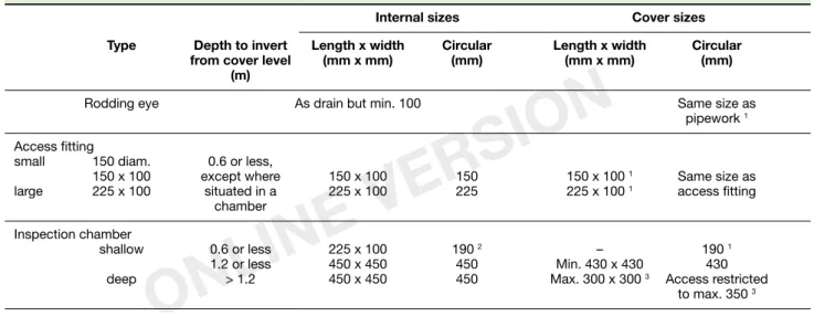
11. Minimum dimensions for access
fittings and inspection chambers 19
12. Minimum dimensions for manholes 20
13. Maximum spacing of access points
in metres 21
14. Materials for access points 21
A1. Flow rates from dwellings 23
A2. Flow rates from appliances 23
A3. Minimum trap sizes and seal depths
additional to Table 2 23
C1. Characteristics that should be considered when designing or laying a shared drain/sewer so that it meets the basic requirements for adoption 28 H3
1. Calculation of drained area 40
2. Gutter sizes and outlet sizes 40
CONTENTS
H
ONLINE
VERSION
ONLINE
VERSION
ONLINE
VERSION
THE APPROVED DOCUMENTS
This document is one of a series that has been approved and issued by the Secretary of State for the purpose of providing practical guidance with respect to the requirements of Schedule 1 to and Regulation 7 of the Building Regulations 2000 (SI 2000/2531) for England and Wales. SI 2000/2531 has been amended by the Building (Amendment) Regulations 2001 (SI 2001/3335). At the back of this document is a list of all the documents that have been approved and issued by the Secretary of State for this purpose. Approved Documents are intended to provide guidance for some of the more common building situations. However, there may well be alternative ways of achieving compliance with the requirements. Thus there is no obligation to adopt anyparticular solution contained in an Approved Document if you prefer to meet the relevant requirement in some other way.
Other requirements
The guidance contained in an Approved Document relates only to the particular requirements of the Regulations which the document addresses. The building work will also have to comply with the requirements of any other relevant paragraphs in Schedule 1 to the Regulations.
There are Approved Documents which give guidance on each of the Parts of Schedule 1 and on Regulation 7.
LIMITATION ON REQUIREMENTS
In accordance with Regulation 8, the requirements in Parts A to K and N (except for paragraphs H2 and J6) of Schedule 1 to the Building Regulations do not require anything to be done except for the purpose of securing reasonable standards of health and safety for persons in or about buildings (and any others who may be affected by buildings or matters connected with buildings).Paragraphs H2 and J6 are excluded from Regulation 8 because they deal directly with prevention of the contamination of water. Parts L and M are excluded because they respectively address the conservation of fuel and power and access and facilities for disabled people. These matters are amongst the purposes, other than health and safety, that may be addressed by Building Regulations.
MATERIALS AND WORKMANSHIP
Any building work which is subject to the requirements imposed by Schedule 1 to the Building Regulations should, in accordance with Regulation 7, be carried out with proper materials and in a workmanlike manner.You may show that you have complied with Regulation 7 in a number of ways. These include the appropriate use of a product bearing CE Marking in accordance with the Construction Products Directive (89/106/EEC)1 as amended
by the CE Marking Directive (93/68/EEC)2 , or a
product complying with an appropriate technical specification (as defined in those Directives), a British Standard, or an alternative national technical specification of any state which is a contracting party to the European Economic Area which, in use, is equivalent, or a product covered by a national or European certificate issued by a European Technical Approval issuing body, and the conditions of use are in accordance with the terms of the certificate. You will find further guidance in the Approved Document supporting Regulation 7 on materials and workmanship. Independent certification schemes
There are many UK product certification schemes. Such schemes certify compliance with the requirements of a recognised document which is appropriate to the purpose for which the material is to be used. Materials which are not so certified may still conform to a relevant standard.
Many certification bodies which approve such schemes are accredited by UKAS.
Technical specifications
Under Section 1(a) of the Building Act, Building Regulations may be made for various purposes including health, safety, welfare, convenience, conservation of fuel and power and prevention of contamination of water. Standards and technical approvals are relevant guidance to the extent that they relate to these considerations. However, they may also address other aspects of performance, such as serviceability, or aspects which, although they relate to the purposes listed above, are not covered by the current Regulations.
When an Approved Document makes reference to a named standard, the relevant version of the standard is the one listed in ‘Standards referred to’. However, if this version has been revised or updated by the issuing standards body, the new version may be used as a source of guidance provided it continues to address the relevant requirements of the Regulations.
The appropriate use of a product which complies with a European Technical Approval as defined in the Construction Products Directive will meet the relevant requirements.
Use of guidance
1 As implemented by the Construction Products Regulations 1991
(SI 1991/1620).
As implemented by the Construction Products (Amendment) Regulations
H
ONLINE
VERSION
ONLINE
VERSION
ONLINE
VERSION
The Department intends to issue periodic amendments to its Approved Documents to reflect emerging harmonised European Standards. Where a national standard is to be replaced by a harmonised European Standard, there will be a co-existence period during which either standard may be referred to. At the end of the co-existence period the national standard will be withdrawn.
THE WORKPLACE (HEALTH,
SAFETY AND WELFARE)
REGULATIONS 1992
The Workplace (Health, Safety and Welfare) Regulations 1992 contain some requirements which affect building design. The main
requirements are now covered by the Building Regulations, but for further information see
Workplace health, safety and welfare. Workplace (Health, Safety and Welfare) Regulations 1992.
Approved Code of Practice L24. Published by
HSE Books 1992 (ISBN 0 7176 0413 6). The Workplace (Health, Safety and Welfare) Regulations 1992 apply to the common parts of flats and similar buildings if people such as cleaners and caretakers are employed to work in these common parts. Where the requirements of the Building Regulations that are covered by this Part do not apply to dwellings, the provisions may still be required in the situations described above in order to satisfy the Workplace Regulations.
SAFE WORKING IN DRAINS
AND SEWERS
Laying and maintaining drains are hazardous operations. Appropriate safety codes should be followed including procedures for working in confined spaces. Safe working procedures and permits to work may be required in some situations. Relevant statutory requirements can be found in the Construction (Health, Safety and Welfare) Regulations 1996, SI 1996/1592, the Construction (Design and Management) Regulations 1994, SI 1994/3140 and the Confined Spaces Regulations 1997, SI 1997/1713.
The Health and Safety Executive operates an Information Line on 08701 545500, and produces the following advisory codes and information leaflets related to earthworks, drainage and working in confined spaces which are available from HSE Books, Tel 01787 881165.
Health and Safety in Excavation – be safe and
shore, Booklet HSG 185.
Safe Work in Confined Spaces – Approved
Code of Practice, Regulations and Guidance,
Booklet L101.
USE OF GUIDANCE
H
ONLINE
VERSION
ONLINE
VERSION
ONLINE
VERSION
This Approved Document, which takes effect on 1 April 2002, deals with the following Requirement which is contained in the Building Regulations 2000 (as amended by SI 2001/3335).
Requirement Limits on application
Foul water drainage
H1. (1) An adequate system of drainage shall be provided to
carry foul water from appliances within the building to one of the following, listed in order of priority:
(a) a public sewer; or, where that is not reasonably
practicable,
(b) a private sewer communicating with a public
sewer; or, where that is not reasonably practicable,
(c) either a septic tank which has an appropriate
form of secondary treatment or another wastewater treatment system; or, where that is not reasonably practicable,
(d) a cesspool.
(2) In this Part ‘foul water’ means waste water which
comprises or includes:
(a) waste from a sanitary convenience, bidet or
appliance used for washing receptacles for foul waste; or
(b) water which has been used for food preparation,
cooking or washing.
Requirement H1 does not apply to the diversion of water which has been used for personal washing or for the washing of clothes, linen or other articles to collection systems for re-use.
The Requirement
Performance
In the Secretary of State’s view the requirement of H1 will be met if a foul water drainage system: a. conveys the flow of foul water to a foul water
outfall (a foul or combined sewer, a cesspool, septic tank or holding tank);
b. minimises the risk of blockage or leakage; c. prevents foul air from the drainage system
from entering the building under working conditions;
d. is ventilated;
e. is accessible for clearing blockages; and f. does not increase the vulnerability of the
Introduction to provisions
0.1 The capacity of the system should be large enough to carry the expected flow at any point. 0.2 The capacity depends on the size and gradient of the pipes. Minimum sizes and gradient limits are given in the text.
0.3 The pipe sizes quoted in this document are nominal sizes used as a numerical designation in convenient round numbers approximately equal to a manufacturer’s size. Equivalent pipe sizes for individual pipe standards will be found in the standards listed in Tables 4, 7 and 14.
Guidance
H1
FOUL WATER DRAINAGE
ONLINE
VERSION
ONLINE
VERSION
ONLINE
VERSION
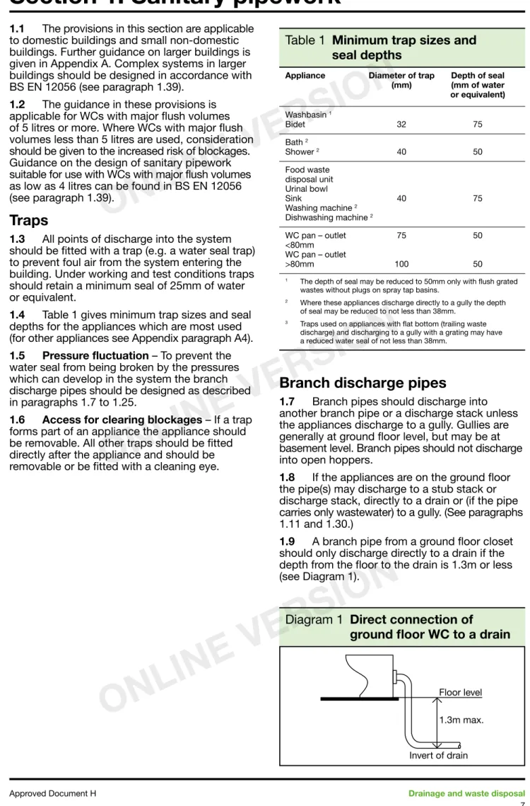
1.1 The provisions in this section are applicable to domestic buildings and small non-domestic buildings. Further guidance on larger buildings is given in Appendix A. Complex systems in larger buildings should be designed in accordance with BS EN 12056 (see paragraph 1.39).
1.2 The guidance in these provisions is applicable for WCs with major flush volumes of 5 litres or more. Where WCs with major flush volumes less than 5 litres are used, consideration should be given to the increased risk of blockages. Guidance on the design of sanitary pipework suitable for use with WCs with major flush volumes as low as 4 litres can be found in BS EN 12056 (see paragraph 1.39).
Traps
1.3 All points of discharge into the system should be fitted with a trap (e.g. a water seal trap) to prevent foul air from the system entering the building. Under working and test conditions traps should retain a minimum seal of 25mm of water or equivalent.
1.4 Table 1 gives minimum trap sizes and seal depths for the appliances which are most used (for other appliances see Appendix paragraph A4). 1.5 Pressure fluctuation – To prevent the water seal from being broken by the pressures which can develop in the system the branch discharge pipes should be designed as described in paragraphs 1.7 to 1.25.
1.6 Access for clearing blockages – If a trap forms part of an appliance the appliance should be removable. All other traps should be fitted directly after the appliance and should be removable or be fitted with a cleaning eye.
Table 1
Minimum trap sizes and
seal depths
Appliance Diameter of trap Depth of seal (mm) (mm of water or equivalent) Washbasin 1 Bidet 32 75 Bath 2 Shower 2 40 50 Food waste disposal unit Urinal bowl Sink 40 75 Washing machine 2 Dishwashing machine 2 WC pan – outlet 75 50 <80mm WC pan – outlet >80mm 100 50
1 The depth of seal may be reduced to 50mm only with flush grated
wastes without plugs on spray tap basins.
2 Where these appliances discharge directly to a gully the depth
of seal may be reduced to not less than 38mm.
3 Traps used on appliances with flat bottom (trailing waste
discharge) and discharging to a gully with a grating may have a reduced water seal of not less than 38mm.
Branch discharge pipes
1.7 Branch pipes should discharge into another branch pipe or a discharge stack unless the appliances discharge to a gully. Gullies are generally at ground floor level, but may be at basement level. Branch pipes should not discharge into open hoppers.
1.8 If the appliances are on the ground floor the pipe(s) may discharge to a stub stack or discharge stack, directly to a drain or (if the pipe carries only wastewater) to a gully. (See paragraphs 1.11 and 1.30.)
1.9 A branch pipe from a ground floor closet should only discharge directly to a drain if the depth from the floor to the drain is 1.3m or less (see Diagram 1).
Section 1: Sanitary pipework
Diagram 1
Direct connection of
ground floor WC to a drain
H1
ONLINE
VERSION
ONLINE
VERSION
ONLINE
VERSION
1.10 A branch pipe should not discharge into a stack in a way which could cause crossflow into any other branch pipe. (See Diagram 2.)
1.11 A branch discharge pipe should not discharge into a stack lower than 450mm above the invert of the tail of the bend at the foot of the stack in single dwellings of up to 3 storeys (see Diagram 2). (For multi-storey buildings this should be increased, see Appendix paragraphs A5 and A6.) 1.12 Branch pipes may discharge into a stub stack. (See paragraph 1.30.)
1.13 A branch pipe discharging to a gully should terminate between the grating or sealing plate and the top of the water seal.
1.14 Condensate drainage from boilers may be
connected to sanitary pipework. The connection should be made using pipework of minimum diameter 22mm through a 75mm condensate trap. If an additional trap is provided externally to the boiler to provide the 75mm seal, an air gap should be provided between the boiler and the trap. a. The connection should preferably be made to an internal stack with a 75mm condensate trap. b. If the connection is made to a branch pipe,
the connection should be made downstream of any sink waste connection.
c. All sanitary pipework receiving condensate should be made from materials resistant to a pH value of 6.5 and lower. The installation should be in accordance with BS 6798. 1.15 Sizes of branch pipes – Pipes serving a single appliance should have at least the same diameter as the appliance trap (see Table 1). If a pipe serves more than one appliance, and is unventilated, the diameter should be at least the size shown in Table 2.
1.16 Bends in branch pipes should be avoided
if possible. Where they cannot they should have as large a radius as possible.
1.17 Junctions on branch pipes of about the same diameter should be made with a sweep of 25mm radius or at 45°. Connection of branch pipes of 75mm diameter or more to a stack of equal diameter should be made with a sweep of 50mm minimum radius or at 45°.
1.18 Branch pipes up to 40mm diameter joining branch pipes 100mm diameter or greater should, if practicable, connect to the upper part of the pipe wall of the larger branch.
1.19 Ventilation of branch pipes – separate ventilation will not be needed to prevent the water seals in traps from being lost by pressures which can develop in the system if the length and slope of the branch discharge pipes do not exceed those shown in Table 2 or Diagram 3.
Diagram 2
Branch connection to stacks – crossflow prevention
H1
SANITARY PIPEWORK
ONLINE
VERSION
ONLINE
VERSION
ONLINE
VERSION
Table 2
Common branch discharge pipes (unventilated)
Appliance Max. no. to Max. length of Min. size of Gradient limits be connected branch pipe (m) pipe (mm) (mm fall per metre)
WC outlet > 80mm 8 15 100 18 2 to 90 WC outlet < 80mm 1 15 75 3 18 to 90 Urinal – bowl 3 1 50 Urinal – trough 3 1 65 18 to 90 Urinal – slab 3 1 Washbasin or bidet 3 1.7 30 18 to 22 1.1 30 18 to 44 0.7 30 18 to 87 3.0 40 18 to 44 4 4.0 50 18 to 44
1 Should be as short as possible to prevent deposition.
2 May be reduced to 9mm on long drain runs where space is restricted, but only if more than one WC is connected.
3 Not recommended where disposal of sanitary towels may take place via the WC, as there is an increased risk of blockages.
4 Slab urinals longer than seven persons should have more than one outlet.
Diagram 3
Branch connections
SANITARY PIPEWORK
H1
ONLINE
VERSION
ONLINE
VERSION
ONLINE
VERSION
1.20 If the figures in Table 2 and Diagram 3 are exceeded the branch pipe should be ventilated by a branch ventilating pipe to external air, to a ventilating stack (ventilated branch system) or internally by use of an air admittance valve. 1.21 A separate ventilating stack is only likely to be preferred where the numbers of sanitary appliances and their distance to a discharge stack are large. (See Appendix paragraphs A7 to A9.) 1.22 Branch ventilating pipes – should be connected to the discharge pipe within 750mm of the trap and should connect to the ventilating stack or the stack vent, above the highest ‘spillover’ level of the appliances served (see Diagram 4). The ventilating pipe should have a continuous incline from the discharge pipe to the point of connection to the ventilating stack or stack vent.
1.23 Branch ventilating pipes which run direct to outside air should finish at least 900mm above any opening into the building nearer than 3m (see Diagram 6 and paragraph 1.31).
1.24 Branch ventilating pipes to branch pipes serving one appliance should be at least 25mm diameter or where the branch is longer than 15m or has more than 5 bends, should be at least 32mm. 1.25 Rodding points should be provided to give access to any lengths of discharge pipe which cannot be reached by removing traps or appliances with internal traps (see paragraph 1.6).
Discharge stacks
1.26 All stacks should discharge to a drain. The bend at the foot of the stack should have as large a radius as possible and at least 200mm at the centre line.
1.27 Offsets in the ‘wet’ portion of a discharge stack should be avoided. If they are unavoidable then in a building of not more than 3 storeys there should be no branch connection within 750mm of the offset. In a building over 3 storeys a ventilation stack may be needed with connections above and below the offset. In buildings over
3 storeys discharge stacks should be located inside the building.
1.28 Sizes of stacks – Stacks should have at least the diameter shown in Table 3 and should not reduce in the direction of flow. Stacks serving urinals should be not less than 50mm, stacks serving closets with outlets less than 80mm should be not less than 75mm and stacks serving closets with outlets greater than 80mm should be not less than 100mm. The internal diameter of the stack should be not less than that of the largest trap or branch discharge pipe. For larger buildings the maximum flow should be checked. (See paragraphs A.1 to A.3.)
Table 3
Minimum diameters for
discharge stacks
Stack size Max. capacity (mm) (litres/sec) 50* 1.2 65* 2.1 75† 3.4 90 5.3 100 7.2 Notes: * No WCs.
† Not more than 1 WC with outlet size <80mm.
1.29 Ventilation of discharge stacks – To prevent water seals in the traps from being lost by pressures which can develop in the system, discharge stacks should be ventilated. Discharge stacks connected to drains liable to surcharging or near an intercepting trap require ventilating pipes of not less than 50mm diameter connected to the base of the stack above the likely flood level. 1.30 Stub stacks – A stub stack may be used if it connects into a ventilated discharge stack or into a ventilated drain not subject to surcharging and no connected water closet has a floor level more than 1.3m and no other branch into the stub stack has a centreline more than 2m to the centre line above the invert of the connection or drain (see Diagram 5).
Diagram 4
Branch ventilation pipes
H1
SANITARY PIPEWORK
ONLINE
VERSION
ONLINE
VERSION
ONLINE
VERSION
1.31 Ventilating pipes open to outside air should finish at least 900mm above any opening into the building within 3m and should be finished with a wire cage or other perforated cover, fixed to the end of the ventilating pipe, which does not restrict the flow of air (see Diagram 6). In areas where rodent control is a problem (see paragraph 2.22) these should be metallic.
1.32 Sizes of stack ventilation pipes – stack ventilation pipes (the dry part above the highest branch) may be reduced in size in one and two storey houses, but should be not less than 75mm. 1.33 Ventilated discharge stacks may be terminated inside a building when fitted with air admittance valves complying with BS EN 12380:2002. Where these valves are used they should not adversely affect the amount of ventilation necessary for the below ground system which is normally provided by open stacks of the sanitary pipework. Air admittance valves should be located in areas which have
adequate ventilation, should be accessible for maintenance and should be removable to give access for clearance of blockages. Air admittance valves should not be used outside buildings or in dust laden atmospheres. Where there is no open ventilation on a drainage system or through connected drains, alternative arrangements to relieve positive pressures should be considered. 1.34 Access for clearing blockages – rodding points should be provided in discharge stacks to give access to any lengths of pipe which cannot be reached from any other part of the system. All pipes should be reasonably accessible for repair. Rodding points in stacks should be above the spillover level of appliances.
Materials for pipes, fittings
and joints
1.35 Any of the materials shown in Table 4 may be used (the references are to British Standard or European Standard Specifications). Where necessary different metals should be separated by non-metallic material to prevent electrolytic corrosion. Care should be taken to ensure continuity of any electrical earth bonding requirements. Pipes should be firmly supported without restricting thermal movement. Attention is also drawn to the requirement of Part B of Schedule 1 to the Building Regulations 2000 and guidance in the Approved Document relating to penetration of fire separating elements and fire
stopping provisions.
Table 4
Materials for sanitary pipework
Material British Standard Pipes Cast iron BS 416, BS EN 877 Copper BS EN 1254, BS EN 1057 Galvanised steel BS 3868 PVC-U BS EN 1329 Polypropylene (PP) BS EN 1451 ABS BS EN 1455 Polyethylene (PE) BS EN 1519 Styrene copolymer blends (PVC + SAN) BS EN 1565 PVC-C BS EN 1566 Traps BS EN 274, BS 3943
Note: Some of these materials may not be suitable for carrying trade effluent or condensate from boilers.
1.36 Sanitary pipework connected to WCs
should not allow light to be visible through the pipe wall, as this is believed to encourage damage by rodents.
Diagram 5
Stub stack
Diagram 6
Termination of ventilation
stacks or ventilation part of
discharge
SANITARY PIPEWORK
H1
ONLINE
VERSION
ONLINE
VERSION
ONLINE
VERSION
Workmanship
1.37 Good workmanship is essential.
Workmanship should be in accordance with BS 8000 Workmanship on Building Sites Part 13:
Code of practice for above ground drainage.
Air tightness
1.38 The pipes, fittings and joints should be capable of withstanding an air test of positive pressure of at least 38mm water gauge for at least 3 minutes. Every trap should maintain a water seal of at least 25mm. Smoke testing may be used to identify defects where a water test has failed. Smoke testing is not recommended for PVC-U pipes.
Alternative approach
1.39 The requirement can also be met by following the relevant recommendations of BS EN 12056 Gravity drainage systems inside
buildings. Relevant clauses are in Part 1: General
and performance requirements, Clauses 3–6;
Part 2 Sanitary pipework, layout and calculation, Clauses 3 to 6 and National Annexes NA to NG (System III is traditionally in use in the UK); Part 5
Installation and testing, instructions for operation,
maintenance and use, Clauses 4–6, 8, 9 and 11.
BS EN 12109 Vacuum Drainage Systems
Inside Buildings.
H1
SANITARY PIPEWORK
ONLINE
VERSION
ONLINE
VERSION
ONLINE
VERSION
2.1 This section gives guidance on the construction of underground drains and sewers from buildings to the point of connection to an existing sewer or a cesspool or wastewater treatment system and includes any drains or sewers outside the curtilage of the building. Disused and defective pipework is known to harbour rats (see Appendix H1-B).
2.2 Some public sewers may carry foul water and rainwater in the same pipes. If the drainage system is also to carry rainwater to such a sewer, the following provisions still apply but the pipe sizes may need to be increased to carry the combined flows (see paragraph 2.35). In some circumstances, separate drainage should still be provided (see Approved Document H5).
Outlets
2.3 Foul drainage should be connected to a public foul or combined sewer wherever this is reasonably practicable. For small developments connection should be made to a public sewer where this is within 30m provided that the developer has the right to construct the drainage over any intervening private land. Where levels do not permit drainage by gravity a pumping installation should be provided (see paragraphs 2.36 to 2.39).
2.4 For larger developments it may be economic to connect to a public sewer even where the sewer is some distance away. For developments comprising more than one curtilage, the developer may requisition a sewer from the sewerage undertaker who has powers to construct sewers over private land (see Appendix H1-C, C.4). 2.5 The sewerage undertaker should be notified at least three weeks before it is intended to connect to the public sewer (see Appendix H1-C, C.7).
2.6 Where it is not reasonably practicable to connect to a public sewer, it may be possible to connect to an existing private sewer that connects with a public sewer. The permission of the owner or owners of the sewer will be required. The sewer should be in satisfactory condition and have sufficient capacity to take the additional flows. 2.7 Where none of these options is reasonably practicable, a wastewater treatment system or cesspool should be provided (see Approved Document H2).
Surcharging of drains
2.8 Combined and rainwater sewers are designed to surcharge (i.e. the water level in the manhole rises above the top of the pipe) in heavy rainfall. Some foul sewers also receive rainwater and therefore surcharge. For low-lying sites (where the ground level of the site or the level of a basement is below the ground level at the point
where the drainage connects to the public sewer) care should be taken to ensure that the property is not at increased risk of flooding. In all such cases the sewerage undertaker should be consulted to determine the extent and possible frequency of the likely surcharge.
2.9 For basements containing sanitary appliances, where the risk of flooding due to surcharge of the sewer is considered by the sewerage undertaker to be high, the drainage from the basement should be pumped (see paragraphs 2.36 to 2.39). Where the risk is considered to be low an anti-flooding valve should be installed on the drainage from the basement.
2.10 For other low-lying sites (i.e. not basements) where risk is considered low, sufficient protection for the building may be possible by provision of a gully outside the building at least 75mm below the floor level. This should be positioned so that any flooding from the gully will not damage any buildings. In higher risk areas an anti-flooding valve should be provided, or the drainage system pumped (see paragraph 2.36 to 2.39).
2.11 Anti-flooding valves should preferably be of the double valve type, and should be suitable for foul water and have a manual closure device. They should comply with the requirements of prEN 13564. A single valve should not normally serve more than one building. A notice should be provided inside the building to indicate that the system is drained through such a valve. This notice should also indicate the location of any manual override, and include advice on necessary maintenance.
2.12 All drainage unaffected by surcharge should by-pass the protective measures and discharge by gravity.
Layout
2.13 The layout of the drainage system should be kept simple. Changes of direction and gradient should be minimised and as easy as practicable. Access points should be provided only if
blockages could not be cleared without them. 2.14 Connection of drains to other drains or private or public sewers, and of private sewers to public sewers, should be made obliquely, or in the direction of flow.
2.15 Connections should be made using
prefabricated components. Where holes are cut in pipes a drilling device should be used to avoid damaging the pipe.
2.16 Where connections made to existing drains or sewers involve removal of pipes and insertion of a junction, repair couplings should be used to ensure a watertight joint and the junction should be carefully packed to avoid differential settlement with adjacent pipes.
Section 2: Foul drainage
H1
ONLINE
VERSION
ONLINE
VERSION
ONLINE
VERSION
2.17 Sewers (serving more than one property) should be kept as far as is practicable away from the point on a building where a future extension is likely (e.g. rear of a house, or side of house where there is room for a side extension).
2.18 The system should be ventilated by a flow of air. A ventilating pipe should be provided at or near the head of each main drain. An open ventilating pipe (without an air admittance valve) should be provided on any drain fitted with an intercepting trap (particularly on a sealed system), and on any drain subject to surcharge. Ventilated discharge stacks may be used (see paragraphs 1.27 and 1.29). Ventilating pipes should not finish near openings in buildings (see paragraph 1.31). 2.19 Pipes should be laid to even gradients and any change of gradient should be combined with an access point (see paragraph 2.49).
2.20 Pipes should also be laid in straight lines where practicable but may be laid to slight curves if these can still be cleared of blockages. Any bends should be limited to positions in or close to inspection chambers or manholes (see paragraph 2.49) and to the foot of discharge and ventilating stacks. Bends should have as large a radius as practicable.
2.21 Drainage serving kitchens in commercial hot food premises should be fitted with a grease separator complying with BS EN 1825-1:2004 and designed in accordance with BS EN 1825-2:2002 or other effective means of grease removal.
Special protection –
rodent control
2.22 Where the site has been previously
developed the local authority should be consulted to determine whether any special measures are necessary for control of rodents. Special measures which may be taken include the following.
a. Sealed drainage – drainage having access covers to the pipework in the inspection chamber instead of an open channel. These should only be used in inspection chambers, where maintenance can be carried out from the surface without personnel entry.
b. Intercepting traps – These are susceptible to blockage and require frequent maintenance. Intercepting trap stoppers should be of the locking type that can be easily removed from the chamber surface and securely replaced after blockage clearance. It is important that stoppers are replaced after maintenance. These should only be used in inspection chambers where maintenance can be carried out from the surface without personnel entry.
c. Rodent barriers – a number of rodent barrier devices are used in other countries; these include: enlarged sections on discharge stacks to prevent rats climbing, flexible downward facing fins in the discharge stack, or one way valves in underground drainage. d. Metal cages on ventilator stack terminals
should also be used to discourage rats from leaving the drainage system (see paragraph 1.31).
e. Covers and gratings to gullies may be displaced or attacked by rats. Solid plastic covers or metal gratings which can be fixed in place should be used to discourage rats from leaving the system.
Protection from settlement
2.23 A drain may run under a building if at least 100mm of granular or other flexible filling is provided round the pipe. On sites where excessive subsidence is possible additional flexible joints may be advisable or other solutions such as suspended drainage, particularly where the pipe is adjacent to structures or where soil conditions change in the course of the pipe run. Where the crown of the pipe is within 300mm of the underside of the slab, special protection should be provided (see paragraph 2.44).
2.24 At any points where pipes are built into a structure, including an inspection chamber, manhole, footing, ground beam or wall, suitable measures should be taken to prevent damage or misalignment. This may be achieved by either: a. building in a length of pipe (as short as
possible) with its joints as close as possible to the wall faces (within at most 150mm) and connected on each side of rocker pipes by a length of at most 600mm and flexible joints (see Diagram 7(a)); or
b. forming an opening to give at least 50mm clearance all round the pipe and the opening masked with rigid sheet material to prevent ingress of fill or vermin. It is important that the void is also filled with a compressible sealant to prevent ingress of gas (see Diagram 7(b)). 2.25 A drain trench should not be excavated lower than the foundations of any building nearby (see Diagram 8) unless either:
a. where the trench is within 1m of the
foundation the trench is filled with concrete up to the lowest level of the foundation; or b. where the trench is further than 1m from the
building, the trench is filled with concrete to a level below the lowest level for the building equal to the distance from the building, less 150mm.
H1
FOUL DRAINAGE
ONLINE
VERSION
ONLINE
VERSION
ONLINE
VERSION
2.26 Where pipes are to be laid on piles or beams or in a common trench, or where the ground may prove unstable particularly where there is a high water table, advice may be found in TRL A guide to the design loadings
for buried rigid pipes. The local authority may
be able to provide information regarding the site.
Depth of pipe cover
2.27 The depth of cover will usually depend on the levels of the connections to the system, the gradients at which the pipes should be laid and the ground levels.
2.28 Pipes also need to be protected from damage and if the limits of cover are not attainable it may be possible to choose another pipe
strength and pipe bedding class combination (Guidance is given in BS EN 1295-1 National Annex NA). Alternatively special protection can be provided (see paragraphs 2.41 to 2.45).
Pipe gradients and sizes
2.29 Drains should have enough capacity
to carry the flow. The flow depends on the appliances connected (see paragraphs 0.1–0.3 and Table 5) and the capacity depends on the size and gradient of the pipes (see Diagram 9).
Diagram 7
Pipes penetrating walls
Diagram 8
Pipe runs near buildings
Diagram 9
Discharge capacities
of foul drains running
0.75 proportional depth
FOUL DRAINAGE
H1
ONLINE
VERSION
ONLINE
VERSION
ONLINE
VERSION
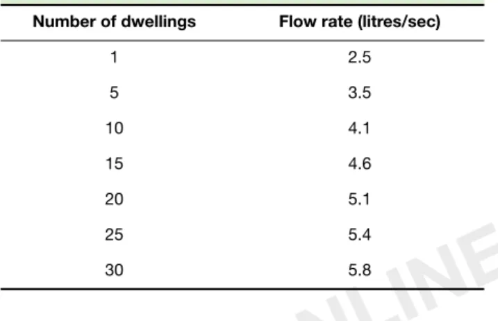
Table 5
Flow rates from dwellings
Number of dwellings Flow rate (litres/sec)
1 2.5 5 3.5 10 4.1 15 4.6 20 5.1 25 5.4 30 5.8
2.30 Sewers (i.e. a drain serving more than one property) should normally have a minimum diameter of 100mm when serving no more than 10 dwellings. Sewers serving more than 10 dwellings should normally have a minimum diameter of 150mm. See also Table C1. 2.31 The flow depends on the type, number and grouping of appliances.
2.32 Appliances are seldom in use
simultaneously and the minimum drain sizes in normal use are capable of carrying the flow from quite large numbers of appliances. Table 5 shows approximate flow rates resulting from the typical household group of 1 WC, 1 bath, 1 or 2 washbasins, 1 sink and 1 washing machine used for design purposes in BS EN 12056.
2.33 A drain carrying foul water should have an internal diameter of at least 75mm. A drain carrying effluent from a WC or trade effluent should have an internal diameter of at least 100mm.
2.34 Table 6 shows the flattest gradients at which drains should be laid (depending on the flow and the appliances connected to them) and the capacity they will then have (see also paragraphs 0.1–0.3).
Table 6
Recommended minimum
gradients for foul drains
Peak flow Pipe size Minimum Maximum (litres/sec) (mm) gradient capacity
(1 in ...) (litres/sec) < 1 75 1:40 4.1 100 1:40 9.2 > 1 75 1:80 2.8 100 1:80* 6.3 150 1:150† 15.0 Notes: * Minimum of 1 WC † Minimum of 5 WCs
2.35 Combined systems – the capacity of
systems carrying foul water and rainwater should take account of the combined peak flow (see Approved Document H3 Rainwater drainage paragraph 3.8).
Pumping installations
2.36 Where gravity drainage is impracticable, or protection against flooding due to surcharge in downstream sewers is required, a pumping installation will be needed.
2.37 Package pumping installations are
available which are suitable for installation within buildings. Floor mounted units may be particularly suited for installation in basements. These should conform to BS EN 12050. Pumping installations for use inside buildings should be designed in accordance with BS EN 12056-4.
2.38 Package pumping installations suitable for installation outside buildings are also available. Guidance on the design of pumping installations for use outside buildings may be found in BS EN 752-6.
2.39 Where foul water drainage from a building is to be pumped, the effluent receiving chamber should be sized to contain 24-hour inflow to allow for disruption in service. The minimum daily discharge of foul drainage should be taken as 150 litres per head per day for domestic use. For other types of building, the capacity of the receiving chamber should be based on the calculated daily demand of the water intake for the building. Where only a proportion of the foul sewage is to be pumped, then the capacity should be based pro-rata. In all pumped systems the controls should be so arranged to optimise pump operation.
Materials for pipes and jointing
Table 7
Materials for below ground
gravity drainage
Material British Standard Rigid pipes Vitrified clay BS 65, BS EN 295 Concrete BS 5911 Grey iron BS 437 Ductile iron BS EN 598 Flexible pipes UPVC BS EN 1401+ PP BS EN 1852+ Structure walled plastic pipes BS EN 13476
+ Application area code UD should normally be specified
Note: Some of these materials may not be suitable for conveying trade effluent
H1
FOUL DRAINAGE
ONLINE
VERSION
ONLINE
VERSION
ONLINE
VERSION
2.40 Any of the materials shown in Table 7 may be used (the references are to British Standard Specifications). Joints should be appropriate to the material of the pipes. To minimise the effects of any differential settlement pipes should have flexible joints. All joints should remain watertight under working and test conditions and nothing in the pipes, joints or fittings should project into the pipe line or cause an obstruction. Different metals should be separated by non-metallic materials to prevent electrolytic corrosion.
Bedding and backfilling
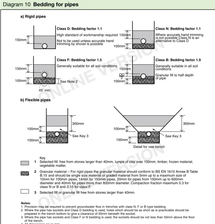
2.41 The choice of bedding and backfilling depends on the depth at which the pipes are to be laid and the size and strength of the pipes.
2.42 Rigid pipes – The types of bedding and backfilling which should be used for rigid pipes of standard strength laid in a trench of any width are shown in Diagram 10 and Tables 8 and 9. Minimum and maximum depths of cover are also shown for each type.
2.43 Flexible pipes – These will become deformed under load and require support to limit the deformation. The bedding and backfilling should be as shown in Diagram 10. Minimum and maximum depths of cover are also shown in Table 10.
2.44 Where pipes have less than the minimum
recommended cover in Table 8, 9 or 10, the pipes should, where necessary, be protected from damage by a reinforced concrete cover slab with a
Diagram 10
Bedding for pipes
FOUL DRAINAGE
H1
ONLINE
VERSION
ONLINE
VERSION
ONLINE
VERSION
flexible filler and at least 75mm of granular material between the top of the pipe and the underside of the flexible filler below the slabs (see Diagram 11 and paragraphs 2.28, 2.42 and 2.43).
2.45 Where it is necessary to backfill the trench with concrete in order to protect nearby foundations (see paragraph 2.25) movement joints formed with compressible board should be provided at each socket or sleeve joint face (see Diagram 12).
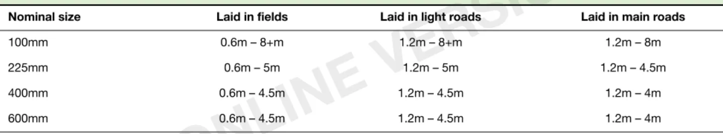
Table 8
Limits of cover for class 120 clayware pipes in any width of trench
Nominal size Laid in fields Laid in light roads Laid in main roads
100mm 0.6m – 8+m 1.2m – 8+m 1.2m – 8m 225mm 0.6m – 5m 1.2m – 5m 1.2m – 4.5m 400mm 0.6m – 4.5m 1.2m – 4.5m 1.2m – 4m 600mm 0.6m – 4.5m 1.2m – 4.5m 1.2m – 4m
Notes:
1. All pipes assumed to be Class 120 to BS EN 295; other strengths and sizes of pipe are available, consult manufacturers.
2. Bedding assumed to be Class B with bedding factor of 1.9; guidance is available on use of higher bedding factors with clayware pipes.
3. Alternative designs using different pipe strengths and/or bedding types may offer more appropriate or economic options using the procedures set out in BS EN 1295.
4. Minimum depth in roads set to 1.2m irrespective of pipe strength.
Table 9
Limits of cover for class M concrete pipes in any width of trench
Nominal size Laid in fields Laid in light roads Laid in main roads
300mm 0.6m – 3m 1.2m – 3m 1.2m – 2.5m 450mm 0.6m – 3.5m 1.2m – 3.5m 1.2m – 2.5m 600mm 0.6m – 3.5m 1.2m – 3.5m 1.2m – 3m
Notes:
1. All pipes assumed to be Class M to BS 5911; other strengths and sizes of pipe are available, consult manufacturers. 2. Bedding assumed to be Class B with bedding factor of 1.9.
3. Alternative designs using different pipe strengths and/or bedding types may offer more appropriate or economic options using the procedures set out in BS EN 1295.
4. Minimum depth in roads set to 1.2m irrespective of pipe strength.
Table 10
Limits of cover for thermoplastics (nominal ring stiffness SN4) pipes in any
width of trench
Nominal size Laid in fields Laid in light roads Laid in main roads
100mm – 300mm 0.6m – 7m 0.9m – 7m 0.9m – 7m
Notes:
1. For drains and sewers less than 1.5m deep and there is a risk of excavation adjacent to the drain and depth, special calculation is necessary, see BS EN 1295.
2. All pipes assumed to be to in accordance with the relevant standard listed in Table 7 with nominal ring stiffness SN4; other strengths and sizes of pipe are available, consult manufacturers.
3. Bedding assumed to be Class S2 with 80% compaction and average soil conditions.
4. Alternative designs using different pipe strengths and/or bedding types may offer more appropriate or economic options using the procedures set out in BS EN 1295.
5. Minimum depth is set to 1.5m irrespective of pipe strength to cover loss of side support from parallel excavations.