Numerical Simulation of Free-Surface
Waves and Wave Induced Separation
S.H. Sadathosseini
1, S.M. Mousaviraad
1, B. Firoozabadi
and G. Ahmadi
2The present study is concerned with the numerical simulation of free-surface waves and wave induced separation in the presence of an intrusion. The results of several simulations are reported. The rst study was performed for a NACA0024 surface piercing hydrofoil over a range of several Froude numbers (0.19, 0.37, 0.55), along with wave breaking at Fr = 1.0 The NACA0024 foil was of particular interest, as it almost has no separation at large depths; thus the eect of the free-surface wave and the wave induced separation could be studied. Free- free-surface waves and wave induced separation results were evaluated and compared with both the available experimental data and the previous numerical results. The wave breaking ow was also successfully simulated and results were presented. The second series of simulations were carried out for a circular cylinder in order to investigate the shape eects on the wave-induced separation. Results suggest that, at high Froude numbers, the free-surface waves are a function of Froude and not the shape of a body. Flow features with regard to separation, free-surface elevations and drag coecients were also studied.
INTRODUCTION
The free-surface wave induced separation is very im-portant in ocean and marine engineering, as well as in naval architecture and oshore structures. The problem involves the complexities of free-surface de-formations coupled with turbulence along with the formidable subject of three-dimensional boundary layer separations. The boundary layer analysis in the pres-ence of the free surface becomes rather complicated, due to the formation of gravity waves and the free-surface boundary condition. For instance, it is known that, for turbulent breaking waves, gravity is eective on large scale motions [1]. Separation due to the free-surface wave, while important in ship and platform hydrodynamics, ship performance, wake signatures and platform stability, is rather poorly understood.
Wave induced separation was rst identied by Chow [2], using vertical (surface piercing) and
hor-1. Department of Mechanical Engineering, Sharif Univer-sity of Technology, P.O. Box: 11155-9567, Tehran, Iran. *. Corresponding Author, Department of Mechanical En-gineering, Sharif University of Technology, P.O. Box: 11155-9567, Tehran, Iran.
2. Department of Mechanical and Aeronautical Engineer-ing, Clarkson University, Potsdam, NY, USA.
izontal (submerged) foils, designed for insignicant separation at large depths. Chow observed regions of separated ow originating just beyond the wave trough and, in some cases, beyond the trailing edge. Wave induced separation was also studied by Stern et al. [3] using a free-surface piercing at plate with an attached wave generating upstream horizontal submerged foil (foil-plate model). As Chow [2] stated, the separation initiated just beyond the wave trough and extended to the following wave crest. These studies showed the dependence of the stream-wise and depth-wise extent of the separation region on the Froude number and wave steepness and, also, that the transverse extent is wedge shaped with signicant free-surface vorticity and turbulence. Choi and Stern [4] performed laminar and turbulent CFD calculations for a surface piercing at plate with an external Stokes wave, which simulates the Stern et al. [3] experimental geometry. Their simulation, however, grossly over/under pre-dicted the experimental data. Zhang and Stern [5] studied the problem using RANS (Reynolds Averaged Navier Stokes) simulation with exact nonlinear kine-matic and approximate dynamic free-surface boundary conditions. The nature of the ow in the separation region was qualitatively similar to Choi and Stern [4], but was described in detail using a derived topological rule [5]. Zhang and Stern [6] also remarked that the
ow is naturally unsteady for high Froude numbers and further numerical and experimental study are both required for accurate analysis of ow characteristics and wave breaking. Pogozelski et al. [7] performed an experimental study of the free-surface wave induced separation, but with dierent foil geometry. Metcalf [8] provided detailed experimental data documentation of the wave elevations and surface pressures for a surface piercing NACA0024 hydrofoil. Kandasamy [9] used CFDSHIP-IOWA (a general purpose research code for ship hydrodynamics) for a RANS simulation of the wave induced separation. They also studied the eects of blockage by considering four dierent solution domains.
There are two distinct approaches in representing the free-surface in a Reynolds-Averaged Navier-Stokes (RANS) simulation, namely, interface tracking and interface capturing. Both approaches aim to compute the wave prole accurately, because the wetted surface area appears in the calculation of drag that acts on ship motion [10]. In interface tracking methods, a kinematic boundary condition is applied at the free-surface and the governing equations are solved only for the water phase [11,12]. Since the computational grids have to conform to the free-surface shape, this approach is not ecient for high Froude number ows, in which breaking waves with high amplitudes are typical. On the other hand, the surface capturing methods are more versatile in handling a variety of free-surface conditions, in which the governing equations are solved for both the air and water phases. Volume-Of-Fluid (VOF) is a widely adopted technique in this category.
This work presents the simulation results for wave formation and wave induced separation using the VOF (Volume-Of-Fluid) technique, which is a robust, free-surface modeling technique and takes the eects of air into consideration. That is, the approach solves RANS equations, simultaneously, for both water and air. Here, the NACA0024 foil was also used for the intrusion geometry, which has an insignicant separation at large depths, thus, making an ideal geometry for isolating the wave induced separation.
The model predictions were compared with the available experimental data and an improvement over the previous numerical calculations was observed. Wave breaking, which occurs at very high Froude num-bers and an intricate problem, was also simulated. The results of wave breaking at Fr = 1.0 are presented, but there were no experimental data or previous numerical results for comparison.
Finally, the shape eects on the free-surface wave induced separation were also studied. A circular cylinder, which has signicant separation at large depths, was modeled to examine the interaction of wave induced and shape induced separations.
COMPUTATIONAL METHOD
The CFD (Computational Fluid Dynamics) results are obtained by solving RANS equations using the nite volume method. The governing equations, continuity and momentum are, as follows:
@Ui
@xj = 0; (1)
@
@xj(UiUj) =
@P @xj
@
@xj(ij+ u 0
iu0j); (2)
where ij =
@Ui
@xj +
@Uj
@xi
is the stress tensor. The treatment for the free-surface ow uses an interface capturing method with the Volume Of Fluid (VOF). In this method, an additional transport equation is solved for the volume fraction of water in each cell. If the volume fraction of water and air in each cell is denoted as w and a, the tracking of the interface
between the phases is accomplished by the solution of a continuity equation for the volume fraction of water. This equation has the following form:
@w
@t + ~U:rw= 0: (3) The volume fraction equation will not be solved for air; the volume fraction of air will be computed based on the following constraint:
w+ a= 1: (4)
The properties appearing in the transport equations are determined by the presence of the component phases in each control volume. For example, the density in each cell is given by the following:
= ww+ aa: (5)
The viscosity was also computed in a similar manner. A single momentum equation is solved throughout the domain and the resulting velocity eld is shared among the phases. The momentum equation is depen-dent on the volume fractions of all phases through the properties, and .
Fluent has the capability to consider surface tension. The simulations were run, with and without considering surface tension, and it appeared that the surface tension had no considerable eect on the re-sults, since other forces are considerably larger than the surface tension force.
The turbulence is modeled using the Reynolds Stress Model (RSM). This model involves the calcu-lation of the individual Reynolds stresses, u0
iu0j, using
dierential transport equations [13]. A single set of transport equations is solved and the Reynolds stresses are shared by the phases throughout the eld. The
individual Reynolds stresses are then used to obtain the closure of the Reynolds averaged momentum equation. This study has been carried out using FLUENT Software [14], version 6.1, to solve the numerical equations. Moreover, grids are generated by Gambit Software in order to discretize the physical domain [14].
TEST CASES
A NACA0024 foil, with a chord length of 1.2 m, a span of 2 m (75% in water) and a thickness of 0.29 cm, is considered as the rst test case.
Three conditions are simulated, with reference to the experimental data, i.e., Fr = (0.19, 0.37, 0.55) and the corresponding Re = (0.822, 1.52, 2.26)106. In
addition, the ow at Fr= 1.0 is also calculated to study the wave breaking ow of the hydrofoil.
Since the geometry is symmetry, only half a do-main, which consists of 215000 hexahedral structured cells, is solved. The cells near the free surface in both air and water elds are designed to be very small (2 mm height) to catch more accurate water deformation results.
The second test case is a circular cylinder, which is vastly used in oshore platforms. Having a diameter of 1.2 m (equal to that of the foil chord length), it is intended to evaluate the shape eects on the wave induced separation.
Figures 1a, 1b and 1c show the geometry and grids. The domain and boundaries are shown in Figure 1a. The boundary condition is \Velocity Inlet" at the inlet and \Out Flow" at the outlet. Also, \Slip Wall" is used for top and bottom boundaries. Moreover, a symmetric condition is used for side and symmetry boundaries.
Figure 1b shows the structural grids generated for the NACA0024 foil and the origin was located at the bottom of the symmetry plane. The initial locations of the free surface for the NACA0024 and the circular cylinder have been shown in Figure 1c. The sizes of grid near the free surface are very small, about 2 mm. The total grid number is 200000 by using symmetric conditions.
Figure 1a. Geometry of the domain.
Figure 1b. Computational grids for the NACA0024 foil.
Figure 1c. The initial free-surface grids of the NACA0024 foil (left) and the circular cylinder (right).
RESULTS AND DISCUSSION
Figure 2 presents the wave prole along the foil and compares it with Zhang & Stern [6] experimental and numerical results for Fr = 0.19. The wave prole is similar to that of a typical ship and the wave length is slightly greater than that given by the Kelvin wave theory, ( = 2Fr2). The results are nearly as accurate as the numerical results of Zhang & Stern [6], indicating that the eects of air on the numerical results of this test case are not signicant at low Froude numbers. The bow wave peak is about 1.6 percent of L.
Figure 3 shows the wave prole along the circular cylinder for Fr = 0.19. The free-surface waves are more dominated by the strong pressure distribution of the blu body than by Kelvin waves that are generated by the high pressure stagnation point. The water piles
Figure 2. Wave prole along the NACA0024 foil for Fr = 0.19.
Figure 3. Wave prole along the circular cylinder for Fr = 0.19.
up in front of the body and, then, the free-surface elevations decrease with an almost constant steepness before the cylinder shoulders. The bow wave peak is almost 6.6 percent of L.
Figures 4 and 5 show the wave proles along the NACA0024 for Fr = 0.37 and Fr = 0.55, respectively. The present modeling agrees better with the exper-imental data, which suggests the signicance of the air eects at higher Froude numbers. It is because, at higher Froude numbers, free-surface elevations are higher and air plays a more critical role. An extreme case is the point at which air trapping occurs. At these Froude numbers, the wave proles are dierent from
Figure 4. Wave prole along the NACA0024 foil for Fr = 0.37.
Figure 5. Wave prole along the NACA0024 foil for Fr = 0.55.
those of ships. The wave proles are relatively at in the separation regions; and this at region is smaller for Fr = 0.55 than for Fr = 0.37. The bow wave peak for Fr = 0.37 and Fr = 0.55 are 6 and 12 percent of L, respectively.
Figures 6 and 7 show the wave proles along the circular cylinder for Fr = 0.37 and Fr = 0.55, respectively. The bow wave peak for Fr = 0.37 and Fr = 0.55 are 9 and 18 percent of L, respectively, which are much greater than those of the NACA0024 foil. Unlike the foil, the wave proles are not at in the separation regions. This shows that, for circular cylinders, the wave pattern is totally dierent and extends further downstream, because of the blunter body shape.
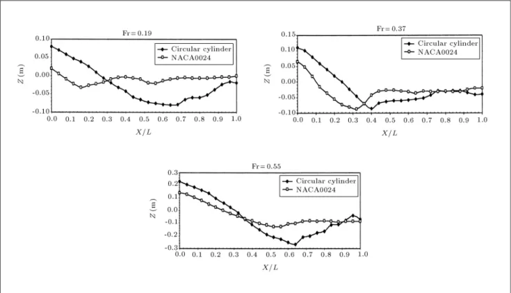
Figure 8 compares the water elevations (wave proles) of the NACA0024 hydrofoil at dierent Froude numbers. For Fr = 0.19, the wave pattern is similar to that of ships. For Fr = 0.37, the bow wave becomes more signicant, the wave steepness is larger and the wave pattern is relatively at in the separation region (from X=L = 0:65 to 1.0). For Fr = 0.55, the free-surface has an even more complicated wave system, with an increase in the bow wave peak, wave steepness and the distortion of the free-surface in the separation region. The elevation of water is negative at the wake region and behind the foil.
Figure 9 compares the wave proles of the circular cylinder at dierent Froude numbers. For Fr = 0.19,
Figure 6. Wave prole along the circular cylinder for Fr = 0.37.
Figure 7. Wave prole along the circular cylinder for Fr = 0.55.
Figure 8. Comparison of the wave proles of the NACA0024 foil at dierent Froude numbers.
Figure 9. Comparison of the wave proles of the circular cylinder at dierent Froude numbers.
the free-surface elevations are aected by the strong pressure distribution of the body, which is similar to that of the circular cylinder at large depths. For Fr = 0.37 and Fr = 0.55, the wave patterns are Froude dependent. The wave height, the wave steepness, and the distortion in the separation region become larger with Froude.
Figure 10 is intended to investigate the shape eects on the wave pattern of surface piercing bodies. For Fr = 0.19, the shape eects are dominant; the wave pattern of the foil is similar to that of ships, mainly aected by the high pressure stagnation point, and the wave pattern of the circular cylinder is aected by the strong pressure distribution of the blunt shaped body. For Fr = 0.37, the wave pattern, i.e. the wave steepness and the trend of the wave elevations, is Froude dependent. However, the bow wave peak and the distortions in the separation region are larger for the circular cylinder, because of its blunt shape. For Fr = 0.55, although the primary pattern of the wave remains Froude dependent, the shape eects seem to become stronger; the wave steepness, the wave height and the distortions in the separation region are more signicantly aected by the shape eects.
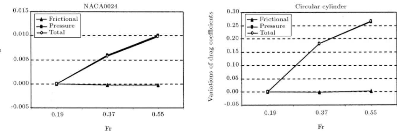
Figure 11 presents the variations of pressure, frictional and total drag coecients versus the Froude number for the NACA0024 and the circular cylinder. All values are subtracted from the corresponding values
Figure 11. Variations of drag coecients versus Fr for the NACA0024 foil and the circular cylinder.
for Fr = 0.19. As Fr increases, the pressure drag coecient increases due to the eects of the bow wave. The frictional drag coecient, on the other hand, decreases as Fr increases from 0.19 to 0.37 and, then increases a little, as Fr increases further to 0.55, which is consistent with the size of the separation region.
Figure 12 shows the pressure contours in the symmetry plane for the NACA0024 foil, in an attempt to show the free-surface elevations around the foil. At low Froude numbers, the waves are found to be insignicant far from the body, unlike Fr = 0.55, at which water deformations are extended behind the trailing edge.
Figure 13 shows the pressure contours for the circular cylinder. The water deformations are consid-erably extended behind the body, especially at Fr = 0.55, to a large distance. Besides, the wake pattern of the circular cylinder is very dierent from that of the NACA0024 foil.
The wave patterns in the wake of the NACA0024 foil and the circular cylinder are presented in Figure 14. Moreover, for one case, the 3-D view of the free surface is shown in Figure 15. For Fr = 0.19, Kelvin waves are generated around the hydrofoil and the wave pattern of the circular cylinder is dominated by the pressure distribution of the blu body. For Fr =
Figure 12. Pressure contours for the NACA0024 foil in the symmetry plane.
Figure 13. Pressure contours for the circular cylinder in the symmetry plane.
Figure 14. Wave patterns of the NACA0024 foil and the circular cylinder.
Figure 15. 3-D view of free surface for circular cylinder at Fr = 0.55.
0.37 and Fr = 0.55, the primary wave patterns of the foil and the circular cylinder are similar, though there are more disorders in the wake of the circular cylinder. This suggests that, at high Froude numbers, the free-surface waves are a function of Froude and not of shape. This means that the gravity waves are dominant in determining wave patterns and the eects of the pressure distribution around the body are limited only to free-surface elevations and not the wave system. Hence, the wave patterns of the NACA0024 foil and the circular cylinder are similar, despite their dierent shapes. The shape eects are evident on the bow wave peak, the extent of the free-surface eects and the distortion in the separation and wake regions.
Figure 16 presents the contours of the X compo-nent of the wall shear stress on the NACA0024 foil. The separation regions, where the wall shear stress values are negative, are also marked in the gure. For Fr = 0.19, the wave eects are limited to the depths very close to the free-surface and the separation region in the free-surface area is very small. Therefore, the ow recovers to 2D at about Z = 0:3 m. For Fr = 0.37, the wave eects become strong, extend to about Z = 1 m, and the separation in the free-surface area starts at about X=L = 0:32. For Fr = 0.55, the wave eects become even stronger and extend to about Z = 1:15
m. The separation region is smaller than that of Fr = 0.37 and the separation in the free-surface area occurs at about X=L = 0:56.
Figure 17 presents the contours of the X compo-nent of the wall shear stress on the circular cylinder. For Fr = 0.19, the location of the separation point in the free-surface area is at about X=L = 0:86, and the separation point at large depths is located at about X=L = 0:67. Therefore, the separation pattern is dominated by the shape eects and the free-surface wave eects only delay the separation. For Fr = 0.37 and Fr = 0.55, the separation points in the free-surface areas are located at about X=L = 0:4 and X=L = 0:64, respectively, which are very dierent from large depths, and close to the NACA0024 hydrofoil. This suggests that, at these high Froude numbers, the separation pattern is Froude dependent and a free-surface wave induced separation is dominant. The shape eects also slightly delay the separation point.
At all Froude numbers, the wave eects for the circular cylinder extend to much larger depths than those of the foil. This indicates that the shape eects are more signicant on the depth-wise extent of the separation region than on its stream-wise extent, especially at high Fr.
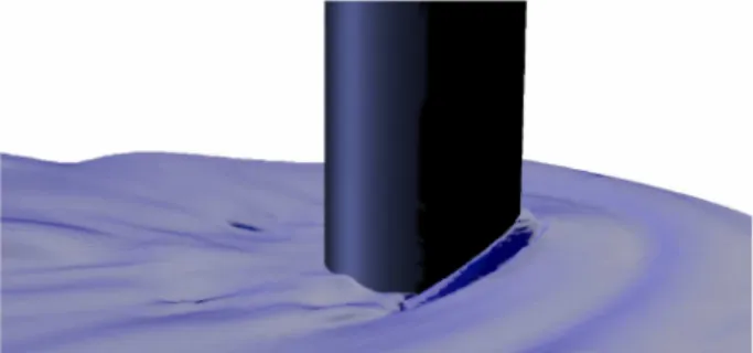
At very high Froude numbers, the ow becomes unsteady and the waves arise and break down period-ically. Figure 18 shows the free-surface waves for the circular cylinder at Fr = 1.0. The phenomenon is ex-tremely complicated, due to the eects of unsteadiness, turbulence and air trapping. The present simulation was able to cope with these diculties; nevertheless, further developments seem to be needed to explain the details of the problem.
CONCLUSIONS
The free-surface ows are evaluated for surface piercing bodies of NACA0024 foil and circular cylinder, over a range of Froude numbers. Flow results are presented
Figure 17. X-wall shear stress contours on the circular cylinder.
Figure 18. Wave breaking of circular cyliner at Fr = 1.
and the wave and viscous nature of the ow separation are discussed.
The study indicates that the drag coecients, the free-surface waves and the separation patterns are all Froude number dependent. The bow wave peak increases with Fr and the separation region increases, as Fr increases from small values of 0.19 to medium values of 0.37 and, then, decreases, as Fr increases further to high values of 0.55. Associated with the wave pattern, the pressure drag coecient increases with Fr. The frictional drag coecient increases and, then, decreases with Fr in agreement with the separation region. This study also shows that air near the free surface aects the accuracy of the numerical modeling signicantly, especially for medium and high Fr.
At very low Fr, the wave induced separation is not strong and shape eects dominate the ow and separation regime. At higher Fr, the wave eects become very signicant and govern the primary pattern
of the separation. However, the depth-wise extent of the separation, despite its stream-wise extent, is highly aected by shape eects. Moreover, the distortions of the wave pattern in the separation and wake regions are shape dependent. For very high Fr, wave breaking occurs and the ow becomes highly unsteady. As a result, robust free surface and turbulence modeling techniques, in addition to ne grids are needed for the numerical simulation. In this work, the wave breaking ow was studied, but additional numerical and experi-mental investigations are needed for identifying details of the ow features.
The present numerical model provides insight into the problem of free-surface wave induced separation and also provides a tool design optimization for ocean engineering applications. Future work includes evalu-ating the performance of dierent turbulence models, assessing the eects of Reynolds number and the criti-cal Froude number at which wave breaking is initiated.
NOMENCLATURE
g acceleration of gravity
L foil chord length & cylinder diameter t time
U1 free-stream velocity
X; Y; Z Cartesian coordinates u0
iu0j Reynolds stresses
~U velocity vector wave length
Kinematic viscosity w volume fraction of water
a volume fraction of air
density viscosity
F r Froude number, pU1
gL
Re Reynolds number, U1L
REFERENCES
1. Brocchini, M. and Peregrine, D.H. \The dynamics of strong turbulence at free-surface. Part1: Description", Journal of Fluid Mechanics, 449, p 225 (2001). 2. Chow, S.K. \Free-surface eects on boundary-layer
separation on vertical struts", PhD Thesis, University of Iowa, USA (June 1967).
3. Stern, F., Hwang, W.S. and Jaw, S.Y. \Eects of waves on the boundary layer of a surface-piercing at plate: experiment and theory", Journal of Ship Research, 33(1), pp 63-80 (1989).
4. Choi, J.E. and Stern, F. \Solid-uid juncture boundary layer and wake with waves", Proc. 6th International Conference on Numerical Ship Hydrodynamics, Iowa City, IA, USA, pp 215-238 (August 1993).
5. Zhang, Z. \Wave-induced separation", M.S. Thesis, University of Iowa, USA (August 1995).
6. Zhang, Z. and Stern, F. \Free-surface wave-induced separation", Journal of Fluids Engineering, 118, pp 546-554 (1996).
7. Pogozelski, E., Katz, J. and Huang, T. \The ow structure around a surface-piercing strut", Physics of Fluids, 9(5), pp 1387-1399 (1997).
8. Metcalf, B. \Experimental investigations of wave-induced separation on a surface-piercing NACA0024 hydrofoil", Thesis, University of Iowa, Iowa City, IA, USA (2001).
9. Kandasamy, M. \RANS simulation of free-surface wave-induced separation on a surface{piercing NACA0024 hydrofoil", Thesis, University of Iowa, Iowa City, IA, USA (2001).
10. Senocak, I. and Iaccarino, G. \progress towards RANS simulation of free-surface ows around modern ships", Center for Turbulence Research, Annual Research Briefs (2005).
11. Li, T., Matusiak, J. and Lehtimaki, R. \Numerical simulation of viscous ows with free-surface around re-alistic hull forms with transom", International Journal for Numerical Method in Fluids, 37, p 601 (2000). 12. Rhee, S.H. and Stern, F. \Unsteady RANS method for
surface ship boundary layer and wake eld", Interna-tional Journal for Numerical Method in Fluids, 37, p 445 (2000).
13. Peri, D., Campana, E.F. and Di Masico, A. \Develop-ment of CFD-based design optimization architecture", First MIT Conference on Computational Fluid and Solid Mechanics, Massachusetts Institute of Technol-ogy, USA, June 12-15 (2001).