ACTA TECHNICA NAPOCENSIS
Series: Applied Mathematics, Mechanics, and Engineering Vol. 60, Issue IV, November, 2017
THE CORRELATION OF THE HYDRAULIC CYLINDERS OF THE
EXCAVATOR FOR OBTAINING A BUCKET OPTIMUM TRAJECTORY
Alexandru VLADEANU, Marcel MIGDALOVICI, Daniela BARAN, Gabriela VLADEANU
Abstract: In the article, a version of control of the bucket position used in the stage of finishing of the digging works executed with the hydraulic excavators with backhoe attachment is presented. This system has the magnetostrictive sensors mounted on the hydraulic cylinders of the working equipment. The relations of calculus for the hydraulic cylinders lengths for manoeuvre of the boom, stick and bucket in function of the bucket cutting edge position are presented. An application for a certain case is presented, establishing the correlation between the hydraulic cylinders lengths for to realize a linear trajectory of digging. The theoretical considerations are used at the identification and approximation through polygon segments of a trajectory which respects a compatible optimization criterion.
Key words: hydraulic excavator, working equipment, hydraulic cylinder, magnetostrictive sensor, the control of the bucket position, optimization.
1. INTRODUCTION
For decreasing the time and increasing the precision of the digging works execution with excavators, the solution of the automatic command of the hydraulic cylinders of the working equipment is imposed for obtaining the given trajectory of the bucket cutting edge, for example a linear trajectory tilted with an angle towards the horizontal, in particular the vertical or horizontal trajectory (fig. 1).
Fig.1. A hydraulic excavator with backhoe attachment used for leveling
The control of position of the bucket cutting edge towards the basis machine can be performed with systems having angle sensors mounted on the boom, stick and bucket or with systems having length sensors of the hydraulic cylinders based on the magnetostrictive principle. In both situations, for the desired trajectory of the bucket cutting edge, the correlation of the movement of the hydraulic cylinders is necessary.
With the purpose to realize this objective through the control of the driven hydraulic cylinders lengths of the boom, stick and bucket, the following problems must be solved:
-the determination of the position angles of the boom, stick and bucket corresponding to a given position of the bucket cutting edge;
-the estimation of the boom, stick and bucket cylinders lengths in function of the position angles of the working equipment;
-the establishment of the correlation necessary between the displacements of the hydraulic cylinders for obtaining a certain trajectory of the bucket cutting edge;
between the displacements of the hydraulic cylinders can be done.
Fig.2. The scheme for determination of the hydraulic cylinders length
2. THE RELATIONS OF CALCULUS FOR THE HYDRAULIC CYLINDERS LENGTH
The following calculus relations were established for the hydraulic cylinders length [10]:
2 2
1 1 2 1 1 cos
AB= O B +O A − ⋅O B O A⋅ ⋅
ψ
in which ψ= α1+ β+ γ, and the notations significance result from figure 2 ( AB – the length of the boom cylinder ; α1 – the position angle of the boom; α1* =π/2−α1; O – the 1 articulation of the boom at the machine basis; A – the articulation of the boom cylinder at the basis machine; B – the articulation of the boom cylinder at the boom).2 2
2 2 2 2 2 cos
CD= O C +O D − ⋅O C O D⋅ ⋅
φ
(2) in which:2 1
3 2
π
φ = − −ε α +α −δ
The significance of other notations results from figure 2 (CD – the length of the manoeuvre cylinder of the stick; α2 – the position angle of the stick; α*2 =π/2−α2; O – the articulation 2 between the boom and stick; O – the 3
articulation between the stick and bucket; C – the articulation of the cylinder stick at the boom; D – the articulation of the stick cylinder at the stick).
2 2
2 cos
EF = EG +FG − ⋅EG FG⋅ ⋅ EGF (3) 2
EGF = π− Σ
2 ( 2 3) ( 3 ) ( )
O GE O GO O GH HGF
Σ = + + +
3 3
3
sin
arcsinO H GO H
O GH
GH ⋅ =
2 2 2
arccos 2
FG HF GH
HGF
FG HF
+ −
=
⋅ ⋅
2 2
3 3 2 3 3 cos 3
GH = O H +O G − ⋅O H O G⋅ ⋅ GO H
3 2 ( 3 2) c ( 3 4)
GO H =
π
− GO O −α
− HO O
2 3
c
α
=π α
− −α
3. THE ESTABLISHMENT OF THE
HYDRAULIC CYLINDERS LENGTHS
FOR OBTAINING A BUCKET OPTIMUM TRAJECTORY
The excavator with a bucket has a cyclic functionality, each cycle having many stages (fig.3): 1 – the descent of the bucket till the neighborhood of the digging place, 2 - the introduction of the bucket cutting edge in the material, 3 – the digging and loading of the bucket with material, 4 – the extraction of the bucket from material and the passing in the raising position, 5 – the raising of the full bucket with material simultaneously with the rotation of the turning platform of the excavator till the bucket arrives above the place of unloading, 6 – bucket unloading.
At the establishing of the bucket optimum trajectory and of the bucket correct position it is considered that for each working cycle stage the specified requirements must be respected, for example:
- The assurance of the optimum digging angle and of the corresponding thickness of the dug clod in function of the type of the material and also the complete loading of the bucket in the digging stage;
-the avoidance of the falling of the earth in the raising stage of the full bucket;
- The assurance of the correct position of the bucket in the unloading stage of the bucket in the vehicle of transportation of the earth.
Fig.3. The bucket positions during the excavator working cycle
The condition that the bucket trajectory during a working cycle to have a minimum length is also imposed for reducing the working time and the consumed energy.
The execution stage of the digging work is also considered. Thus in the finishing stage the optimum digging trajectory is exactly the profile indicated in the project and it is passed from the functionality regime with maximum productivity or from the minimum consume fuel regime at the finishing regime, which allows the increasing of the precision of execution.
All the hydraulic cylinders of the working equipment must be driven simultaneously assuring the correlation of the movements in order that the established trajectory of the cutting edge of the bucket to be covered.
In the following, the necessary correlation between the hydraulic cylinders in the finishing stage of the digging walls is analyzed, case in which the cutting edge trajectory of the bucket must usually be a line segment. In this case a criterion of optimization is the minimum deviation from the indicated profile in the project.
The stick cylinder is chosen as a leader cylinder and the lengths of the boom and of the bucket cylinders can be modified in function of the length of the stick cylinder.
The equation y= f x( ) of the cutting edge trajectory of the bucket is given towards the
1
xO y coordinates system with the origin O1 in the boom articulation at the basis machine and with the horizontal axis O x1 and vertical axis
1
O y. In the particular case from figure 4, the dug surface is plane and the equation of the trajectory has the expression:
( )
i i
y−y =m x−x (4) in which ( , )xi yi are the initial coordinates of
the bucket cutting edge and m=tg( )
γ
1 .In the case in which the optimum established digging trajectory is a curve, this can be approximated with many line segments and the procedure indicated below can be applied on sections.
In each point of the trajectory the bucket position is established (the angle
α
3) such that the ground digging and the bucket loading with ground to be made in the best conditions (the digging angle and the angle of relief of the bucket to be at the optimum values).In the case of the linear trajectory (fig.4), from the condition
β
1+ε
1=const., the position angle of the bucketα
3 results that remains constant during the digging:3 1 1 1
2 k
π
α = +γ −β −ε = (5)
This requirement is assured modifying the length of the bucket cylinder. Also to realize the established trajectory of digging at the same time with the stick cylinder command must be done too the correction of the boom position by the aid of the boom cylinder. For to establish practically how these corrections of the boom and of the bucket position to the stick manoeuvre must be done, it is recommended to do as follows:
4i
O (fig.4) and final one O4f and for each point the angle of position of the bucket
α
3 to be established from the condition that the digging and loading of the bucket to be realized in the optimum conditions;- For each point of the trajectory the position angles of the stick
α
2 and boomα
1 (fig.2) are determined using the relations from below [10]:2 3
1
1 3 3
sin
arcsin( m) arctg O
O
l y
O O x
α
α = ⋅ − (6)
2 ( 1)
2 m
π
α =α − −α (7)
in which
2 2 2
1 2 1 3
1 2 arccos
2 m
l l O O
l l
α
= + −⋅ ⋅
2 2
1 3 3 3
O O = xO +yO
3 3 sin 3; 3 3 cos 3
O O
x = + ⋅x l
α
y = − ⋅y lα
1 2 2 3 3 4
1 ; 2 ; 3
l = O O l = O O l =O O
( , )x y – the coordinates of the considered point on the trajectory
- Knowing the positions angles
α α
1, 2,α
3 of the boom, stick and bucket, the cylinders lengths of the boom, stick and bucket are calculated using the relations (1) – (3);Fig. 4. The scheme for the determination of the position angles of the workingequipment of the hydraulic
excavator
- With the obtained values the graphs of variation of the boom and bucket cylinders lengths are traced, and also the distance covered by the bucket cutting edge in function of the stick cylinder length;
- In the following it can pass to the design of the automatic system of correction of the position of the boom and bucket in function of the stick cylinder length, using the signals from the magnetostrictive position transducers mounted on the hydraulic cylinders of the working equipment.
4. APLICATION
Using a MATLAB program, the established relations for an existing excavator can be applied and the graphs which indicate the necessary corrections of the boom and bucket cylinders lengths are traced for obtaining the linear trajectory of the cutting edge of the bucket at the digging of the tilting ground through the driven by the operator only of the stick cylinder.
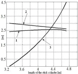
Fig. 5.The correlation of the hydraulic cylinders lengths of the excavator for obtaining a linear dug trajectory
in the considered case.
For this case, the obtaining of the linear trajectory of the bucket, indicated in figure 4, requires a correlation of the displacement of the hydraulic cylinders, such that results from fig. 5. At driving of the stick cylinder by the operator, the position of the boom and of the bucket cylinders must be corrected such that the desired trajectory of the bucket to be obtained. The data for the studied equipment are:
1 2.400 ; 1 0.933
O B = m O A= m
1 1 2 6.466 ; 2 2 3 3.133
l =O O = m l =O O = m
3 3 4 1.866
l = O O = m
2 3.626 ; 2 1.200
O C = m O D= m
2.800 ; 0.800
EG = m FG = m
3
0.666 ; 0.440
HF = m O G = m
= 0.68 rad. ; = 0.383 rad.
β γ
= 2.738 rad. ; = 0.3623 rad.
ε δ
1= 0.697 rad.; 1 = 0.872 rad.
γ
β
1 = 0.174 rad.; 3 = 1.221 rad.
ε
α
5.5 ; 4.95 ; 2.100
i i
x = m y = m h = m
Calculations and the graph from fig.5 were realized using a MATLAB program.
It is observed that in the considered case at a variation of the stick cylinder length of approximately 1.4 m, the necessary variation of the boom length cylinder is only 0.2 m and the correction of the bucket cylinder length is approximately 0.4 m, It results that in the considered case it is possible to renounce at the correction of the boom cylinder length with the drawback that the deviations of the dug surface plane are obtained.
5. CONCLUSIONS
In the finishing stage of the foundation pit walls with the excavator, the bucket position control is imposed, such that the tilts and the dimensions indicated in the project to be obtained. The relations and the established method in the paper, based on the measuring and continue indication of the hydraulic cylinders lengths with magnetostrictive position sensors, allow the accomplishment of some automatic systems of correlation of the hydraulic cylinders with the goal of obtaining
the desired trajectory of the bucket cutting edge in the finishing stage. Driving the hydraulic cylinders and following the display from the cabin, the bucket is positioned with the knife in the initial position with the coordinates xi, yi,
after which the operator set the tilting gradient γ1 and angle of relief of the bucket ε1. In the
following the operator drives the cylinder of the stick and the automatic system assures the necessary corrections for the boom and bucket cylinders lengths such that the desired digging trajectory to be obtained. The boom and bucket cylinders lengths are calculated corresponding to the stick cylinder lengths and comparing the real lengths with those calculated the corrections are made.
It is mentioned that on the display from the cabin are also indicated the position of the equipment at a given time, and also the profile of the pit, and in the preliminary stage of the pit finishing, it is followed that the digging depth indicated in the project to not be exceeded. The solution presented assures the increasing of productivity in the finishing stage of digging and also a higher precision of execution of the works, removing the necessity of periodical performing of some measurements during execution. Also, the solution presented represents another step towards the objective of the automatization and robotization of the hydraulic excavator.
REFERENCES
[1]Teodorescu, P. P., Stanescu, N. D., Pandrea, N.,
Numerical analysis with applications in mechanics and engineering, John Wiley & Sons, Hoboken, USA (2013).
[2] A.J. Koivo, M. Thoma, E. Kocaoglan, J.
Andrade-Cetto, Modeling and control of
excavator dynamics during digging
operation, Journal of aerospace engineering, January 1996
[3] Young Bum Kim, Junhyoung Ha , Hyuk Kang, Pan Young Kim, Jinsoo Park, F.C. Park,
Dynamically optimal trajectories for
earthmoving excavators, Automation in Construction 35 (2013), pag. 568–578
[4] Alvin Anthony, Modeling and analysis of
analysis of excavator system, University of Parma, 2012 (doctoral thesis led by prof. Paolo Casoli)
[5] Howard Cannon, Extended earthmoving with an
autonomous excavator, The Robotics
Institute, Carnegie Mellon University,
Pittsburg, 1999 (masters thesis)
[6] Richard Davidson, Vernon Brabec, Method for
controlling an excavator, patent
5854988/29.12.1998
[7] He, Qinghua Changsha, Electromechani-cally
controlled excavator and method for
controlling the electromechanically
controlled excavator, patent EP 1 835 079 B1/ 2008
[8] Yan Jun, Li Bo, Zeng Yonghua, Qian Haibo, A
rewiew on modeling, identification and servo control of robotic excavator, International
Journal of Engineering, Science and
Technology, vol.5, no.4, 2013
[10] Vlădeanu, A.., Vlădeanu, G., The control of the bucket position at the excavators equipped with sensors of length at the hydraulic cylinders, Proceedings of SISOM, may 2017, Bucharest
[11] Vlădeanu, A.., Vlădeanu, G., The control of the bucket position at the hydraulic excavator with backhoe attachment, Proceedings of SISOM, may 2011, Bucharest
[12]Vlădeanu,A..,Vlădeanu,G., Perfectiona-rea
sistemului de comanda si monitorizare la excavatoare hidraulice, Conferinta ASTR, Galati 2015
[13] Vlădeanu, A.., Vlădeanu, G., Posibilitati de sapare a unor suprafete plane cu excavatoare hidraulice cu cupa inversa, SINUC 2015 [14] Migdalovici, M., Baran, D., and Vlădeanu, G.
Stability Control of Linear and Nonlinear Dynamic Systems, International Journal of Acoustics and Vibration, 21(4), 440-444, (2016).
[15] M. Migdalovici, D. Baran, G. Vlădeanu, "On the Dynamical Systems Stability Control and
Applications", Applied Mechanics and
Materials, Vol. 555, pp. 361-368, 2014. [16] Migdalovici, M., Baran, D., Vladeanu G.,
Dynamical systems stability. Theory and applications (in Romanian), Self-Publishing Printing House, Bucharest, (2013)
[17] Vlădeanu, A.., Vlădeanu, G., The
determination of the bucket position at the excavators with the aid of the tilt sensors,
Proceedings of SISOM, may 2016, Bucharest
[18] Becky Schultz, Komatsu digs in with semi-automatic "intelligent" excavator,
http://www.forconstructionpros.com/article/120199 35/komatsu-digs-in-with-its-pc210lci-10-semi-automatic-intelligent-excavator
Corelarea cilindrilor hidraulici pentru acţionarea echipamentului de lucru al excavatoarelor cu cupă inversă
pentru obţinerea traiectoriei dorite a cupei
Rezumat: In articol se prezinta o varianta de control a pozitiei cupei utilizata in faza de finisare a lucrarilor de sapare executate cu excavatoare hidrauliuce cu cupa inversa si anume sistemul prevazut cu senzori de pozitie magnetostrictivi montati pe cilindrii hidraulici ai echipamentului de lucru. Se stabilesc relatiile de calcul pentru lungimile cilindrilor hidraulici de manevrare a bratului, manerului si cupei in functie de pozitia muchiei taietoare a cupei . Se prezinta o aplicatie pentru un caz concret , stabilindu-se corelarea intre lungimile cilindrilor hidraulici pentru a realiza o traiectorie rectilinie de sapare. Se folosesc consideratiile teoretice la identificarea si aproximarea prin segmente poligonale a unei traiectorii care respecta un criteriu compatibil de optimizare.
Alexandru VLĂDEANU, Professor, Civil Engeneering University from Bucharest, Construction Equipment Faculty, [email protected]
Marcel MIGDALOVICI, Senior researcher grad I, Romanian Academy, Institute of Solid Mechanics, Bucharest, Dynamical Systems, [email protected],
+40213126736.
Daniela BARAN, Senior researcher, INCAS “Elie Carafoli”, Bucharest, Dynamical Systems, [email protected], +40214340083.