This chapter explains how you can troubleshoot a specific problem, such as abnormal LED activity or no system power, when you power up the router.
Diagnosing Problems
Your initial response to a system problem should be to: 1. Check power connections.
2. Observe the system’s LEDs carefully.
3. Check cable connections on the system modules.
If a problem is beyond the scope of this chapter, refer toAppendix C, Cust omer Support for further instructions.
Initialization Sequence
Each E-series line module is initialized independently. As a result, the CLI on the SRP module may become available before the line modules have completed initialization. Commands relating to a line module may fail if the module has not completed initialization. Theshow version command can be used to display line module status. Do not enter commands for a line module until its state is “online.”
Topic Page
Diagnosing Problems 99
Troubleshooting Power Failures 100
Understanding Status LEDs to Troubleshoot 100
Monitoring Temperatures of Modules 107
Resetting Line Modules and SRP Modules 107
Double-Bit Errors on SRP Modules 108
NOTE:Running theshow version andshow hardware commands is often a good first step when trying to troubleshoot a problem.
Troubleshooting Power Failures
The system’s distributed power system is designed to consume low levels of power and dissipate low levels of heat. SeeChapter 11, Sy stem Specifications for
specifications of power consumption and heat dissipation. If you suspect a power problem, refer to Table 11.
Understanding Status LEDs to Troubleshoot
Module LEDs can show you the immediate status of a module and alert you to a problem with the module or one of its ports. It is helpful to familiarize yourself with LED activity so that you can easily detect and correct a module-related problem with minimal or no system downtime.
LED Activity During Booting
When the system boots, it runs a series of tests for each module installed in the system, and the LEDs display various configurations. Refer to the tables in this section to understand normal and abnormal LED activity. For troubleshooting information, see Table 14.
LED Identification
The system’s modules have two sets of status LEDs. The top set indicates generic router and module status. The bottom set indicates module-specific status, such as port status (line modules) or fan status (SRP module).
The number against the port status LED on a line module corresponds to the number of the port on the I/O module. Some line modules have more port status LEDs than the number of ports on the I/O module. In these cases, only the LEDs for the corresponding ports on the I/O modules are active.
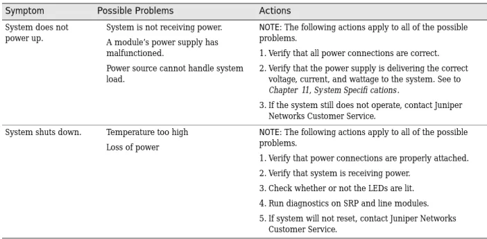
Table 11: Causes of power failures
Symptom Possible Problems Actions
System does not power up.
System is not receiving power. A module’s power supply has malfunctioned.
Power source cannot handle system load.
NOTE: The following actions apply to all of the possible problems.
1. Verify that all power connections are correct. 2. Verify that the power supply is delivering the correct
voltage, current, and wattage to the system. See to
Chapter 11, System Specifi cations.
3. If the system still does not operate, contact Juniper Networks Customer Service.
System shuts down. Temperature too high Loss of power
NOTE: The following actions apply to all of the possible problems.
1. Verify that power connections are properly attached. 2. Verify that system is receiving power.
3. Check whether or not the LEDs are lit. 4. Run diagnostics on SRP and line modules. 5. If system will not reset, contact Juniper Networks
For example, an OCx/STMx line module can pair with either an OC3-4 or an OC12/STM4 I/O module. Consequently, the line module has four port status LEDs for OC3/STM1 operation. However, only the top set of port status LEDs are active during OC12/STM4 operation.
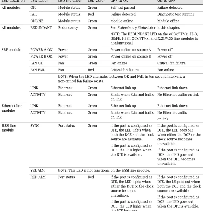
Table 12 shows the functions of the module and port status LEDs.
Table 12: LED identification and activity descriptions
LED Location LED Label LED Indicator LED Color OFF to ON ON to OFF
All modules OK Module status Green Self-test passed Failure detected FAIL Module status Red Failure detected Diagnostic test running ONLINE Module status Green Module online Module offine
All modules REDUNDANT Redundancy Green SeeRedundanc y Statuslater in this chapter.
NOTE: The REDUNDANT LED on the cOCx/STMx, FE-8, GE/FE, HSSI, OCx/STMx, and X.21/V.35 line modules is nonfunctional.
SRP module POWER A OK Power Green Power online on source A Power off POWER B OK Power Green Power online on source B Power off
FAN OK Fan Green Fan online Critical fan failure
FAN FAIL Fan Red Critical fan failure Fan online
NOTE: When the LED alternates between OK and FAIL in ten second intervals, a non-critical fan failure exists.
LINK Ethernet Green Ethernet link up Ethernet link down ACTIVITY Ethernet Green Blinks when Ethernet traffic
on link
No Ethernet traffic on link Ethernet line
modules
LINK Ethernet Green Ethernet link up Ethernet link down ACTIVITY Ethernet Green Blinks when Ethernet traffic
on link
No Ethernet traffic on link
HSSI line module
SYNC Port status Green If the port is configured as DTE, the LED lights when both the DCE and the clock source are available. If the port is configured as DCE, the LED lights when the DTE is available.
If the port is configured as DTE, the LED goes out when either the DCE or the clock source becomes unavailable.
If the port is configured as DCE, the LED goes out when the DTE becomes unavailable.
YEL ALM NOTE: This LED is not functional on the HSSI line module. RED ALM Port status Red If the port is configured as
DTE, the LED lights when either the DCE or the clock source becomes
unavailable.
If the port is configured as DCE, the LED lights when the DTE becomes unavailable.
If the port is configured as DTE, the LE goes out when both the DCE and the clock source are available. If the port is configured as DCE, the LED goes out when the DTE is available.
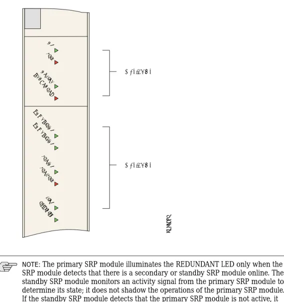
The following figures show a representative module for each of the three variations: SRP module (Figure 52)
Ethernet line module (Figure 53) Other line modules (Figure 54)
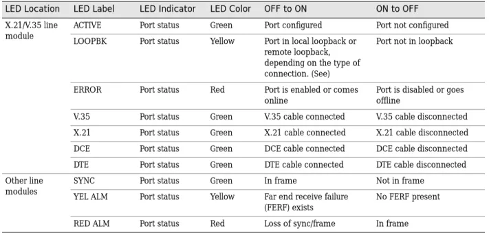
X.21/V.35 line module
ACTIVE Port status Green Port configured Port not configured LOOPBK Port status Yellow Port in local loopback or
remote loopback, depending on the type of connection. (See)
Port not in loopback
ERROR Port status Red Port is enabled or comes online
Port is disabled or goes offline
V.35 Port status Green V.35 cable connected V.35 cable disconnected X.21 Port status Green X.21 cable connected X.21 cable disconnected DCE Port status Green DCE cable connected DCE cable disconnected DTE Port status Green DTE cable connected DTE cable disconnected Other line
modules
SYNC Port status Green In frame Not in frame
YEL ALM Port status Yellow Far end receive failure (FERF) exists
No FERF present RED ALM Port status Red Loss of sync/frame In frame
Table 12: LED identification and activity descriptions (continued)
Figure 52: SRP module LEDs
Status LEDs
Status LEDs
OK FAIL ONLINE REDUNDANT
POWER A OK POWER B OK
FAN OK FAN F
AIL LINK ACTIVITY
g013768
NOTE:The primary SRP module illuminates the REDUNDANT LED only when the SRP module detects that there is a secondary or standby SRP module online. The standby SRP module monitors an activity signal from the primary SRP module to determine its state; it does not shadow the operations of the primary SRP module. If the standby SRP module detects that the primary SRP module is not active, it reboots the system and takes control. (ERX-7xx/14xx models only)
Figure 53: FE2 module LEDs
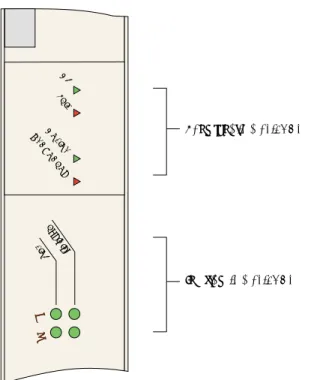
Figure 54: E3 and T3 module LEDs
Functional status LEDs
Interface status LEDs
0 1
OK FAIL ONLIN
E RE
DU ND
ANT
0 1
ACTIVITY LIN
K
g013769
Functional status LEDs
Interface status LEDs OK
FAIL ONLIN
E RE
DU ND
ANT
0 1 2
RED ALM
YEL A
LM
SYNC
LED Activity During Booting
When the system boots, it runs diagnostic tests, and the module status LEDs display various configurations. Observe the scenario presented in Table 13 to verify that the system has booted properly.
If the system detects an error during booting, the FAIL LED turns on. Some failure conditions may cause the board not to boot. In this case, the LEDs may all be off. The system should then reset the board.
If the operational software detects an error, the FAIL LED turns on. Some errors may cause a board reset. Crash information can be displayed from the console and is printed to the screen on the next reboot.
Abnormal LED Activity
See Table 14 to diagnose and correct problems.
NOTE:When you reboot the system after installing a new version of the software, the line modules will appear to boot twice.
Table 13: Normal activity of functional status LEDS during booting
OK FAIL ONLINE Status Process
off on off 1. Module is in the power-up restart state; the FAIL LED stays on briefly.
off off off 2. Module is initializing, and diagnostic tests are running. on off off 3. Module passed the diagnostics; the system boots. on off on 4. Module is now up and running.
Table 14: Troubleshooting abnormal LED activity on modules
Diagnostic Signs Possible Problems Actions
POWER A OK is not lit
POWER B OK is not lit
System is not receiving power from Power A.
System is not receiving power from Power B.
1. Check Power A and Power B terminal connections. 2. Verify that power switches are on.
3. Check connections to power sources.
4. If system still does not operate, contact Juniper Networks Customer Service.
FAIL LED lights The line module and I/O module are incompatible.
A hardware failure, such as a failed module.
1. Check that the line and I/O modules are compatible; replace if necessary.
2. If you replaced the I/O module only, issue thereload
slot slot_number command.
3. If you replaced the line module or if there was a hardware failure, the system should automatically reset the module.
4. If condition persists, contact Juniper Networks Customer Service.
Redundancy Status
You can determine the redundancy state of line modules by examining the online and redundant status LEDs (ERX-7xx/14xx models only). See Table 15.
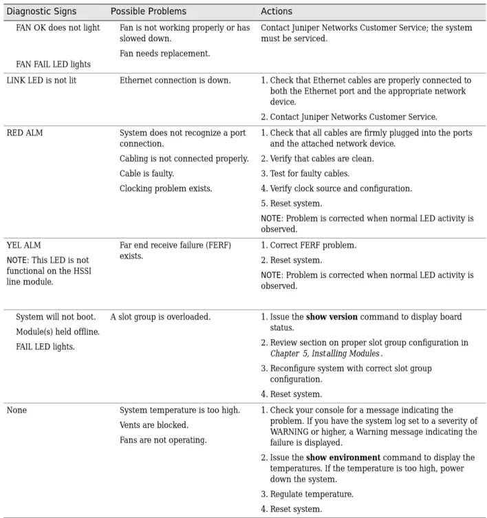
FAN OK does not light
FAN FAIL LED lights
Fan is not working properly or has slowed down.
Fan needs replacement.
Contact Juniper Networks Customer Service; the system must be serviced.
LINK LED is not lit Ethernet connection is down. 1. Check that Ethernet cables are properly connected to both the Ethernet port and the appropriate network device.
2. Contact Juniper Networks Customer Service. RED ALM System does not recognize a port
connection.
Cabling is not connected properly. Cable is faulty.
Clocking problem exists.
1. Check that all cables are firmly plugged into the ports and the attached network device.
2. Verify that cables are clean. 3. Test for faulty cables.
4. Verify clock source and configuration. 5. Reset system.
NOTE:Problem is corrected when normal LED activity is observed.
YEL ALM
NOTE:This LED is not functional on the HSSI line module.
Far end receive failure (FERF) exists.
1. Correct FERF problem. 2. Reset system.
NOTE:Problem is corrected when normal LED activity is observed.
System will not boot. Module(s) held offline. FAIL LED lights.
A slot group is overloaded. 1. Issue theshow version command to display board status.
2. Review section on proper slot group configuration in
Chapter 5, Installing Modules.
3. Reconfigure system with correct slot group configuration.
4. Reset system. None System temperature is too high.
Vents are blocked. Fans are not operating.
1. Check your console for a message indicating the problem. If you have the system log set to a severity of WARNING or higher, a Warning message indicating the failure is displayed.
2. Issue theshow environment command to display the temperatures. If the temperature is too high, power down the system.
3. Regulate temperature. 4. Reset system.
Table 14: Troubleshooting abnormal LED activity on modules (continued)
Diagnostic Signs Possible Problems Actions
NOTE:The REDUNDANT LED on the cOCx/STMx, FE-8, GE/FE, HSSI, and OCx/STMx modules is nonfunctional.
Monitoring Temperatures of Modules
You can view the temperature of each module by issuing theshow environment all
andshow environment table commands. In addition, the system generates
detailed log messages if the temperature of a module is outside normal operating limits.
If the temperature of any module exceeds the upper temperature limit, the system immediately goes into thermal protection mode. Once the system has entered thermal protection mode, you must resolve the cause of the high temperature.
When you have resolved the cause of the high temperature, you must power cycle the system to reset the modules.
Resetting Line Modules and SRP Modules
Two recessed buttons on line modules and SRP modules provide the mechanisms for resetting. You can use the NMI button to reset the software on the module and the board reset button to reset the module. See Figure 12 on page 12.
If a line module fails to respond for an extended time, there may be a software problem with that module. You can depress the software reset button with a paper clip to suspend the current software task. Depending on the situation, this action may also reset the software on the module.
Table 15: Redundancy status of a line module
ONLINE LED REDUNDANT LED State of the Line Module
Off Off Module is booting or is an inactive primary line module. On Off Module is active, but no standby module is available.
Off On Module is in standby state.
On On Module is active, and a standby module is available.
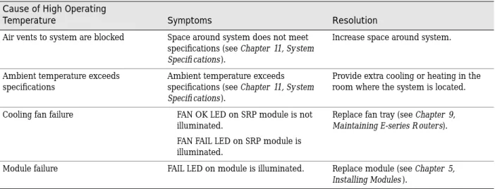
Table 16: Troubleshooting high-temperature conditions Cause of High Operating
Temperature Symptoms Resolution
Air vents to system are blocked Space around system does not meet specifications (seeChapter 11, System Specifi cations).
Increase space around system.
Ambient temperature exceeds specifications
Ambient temperature exceeds specifications (seeChapter 11, System Specifi cations).
Provide extra cooling or heating in the room where the system is located. Cooling fan failure FAN OK LED on SRP module is not
illuminated.
FAN FAIL LED on SRP module is illuminated.
Replace fan tray (seeChapter 9, Maintaining E-series R outers).
Module failure FAIL LED on module is illuminated. Replace module (seeChapter 5, Installing Modules).
If depressing the software reset button fails to correct the issue with the line module, depress the board reset button. This action reboots the line module. The buttons work in the same way for the SRP module. Depressing the board reset button on an SRP module is equivalent to rebooting the E-series router and causes all the line modules to reboot.
Double-Bit Errors on SRP Modules
SRP modules include error checking and correction (ECC) to protect their SDRAM. ECC provides error detection of single-bit and double-bit errors and correction of single-bit errors for the SDRAM as follows:
If ECC detects a single-bit error, it automatically corrects the error, and operation continues.
If ECC detects a double-bit error, it logs the error, stops the main processor on the controller, and takes the SRP module offline.
Detecting Double-Bit Errors
The following message appears on the console if ECC detects a double-bit error: ALERT 05/10/2000 13:10:33 os: failed: ECC DOUBLE BIT ERROR OCCURRED
Address = 0xe95db10
Data (Upper 32Bits) = 0xe95db20 Data (Lower 32Bits) = 0x55d06c ECC Data Bits = 0x2b ECC 1Bit Error Counter = 0x0
*** YOU MUST PERFORM A HARD RESET TO CONTINUE *** ALERT 05/10/2000 13:10:34 os: PROCESSOR EXCEPTION: 0x200n
If ECC detects a double-bit error in a system that contains a redundant SRP module, the redundant module becomes active and the system continues to operate. However, you must still troubleshoot the SRP module with the double-bit error. If ECC detects a double-bit error in a system that does not contain a redundant SRP module, you must troubleshoot the SRP module immediately. SeeFixing Double-Bit Errors.
Fixing Double-Bit Errors
To fix a double-bit error:
1. Remove the second SRP module, if there is one.
2. Reboot the system with the board reset button on the primary SRP module (see Figure 12).
These actions attempt to correct a transient double-bit error. However, if the console displays a memory test failure for the SRP module after you reboot, or if the FAIL LED on the SRP module stays on during rebooting, the SDRAM is permanently damaged and needs replacing. In this event, call Juniper Networks Customer Service to arrange for repair.