512
Common RAID Disk Data Format
Specification
Version 2.0 Revision 19
This document has been released and approved by the SNIA. The SNIA believes that the
ideas, methodologies and technologies described in this document accurately represent
the SNIA goals and are appropriate for widespread distribution. Suggestion for revision
should be directed to http://www.snia.org/feedback/.
SNIA Technical Position
March 27, 2009
Revision History
Revision Date Sections Originator: Comments
1.2 7/28/2006 Arnold Jones Officially published as SNIA Technical Position.
1.20.01 8/16/2006 Bill Dawkins Development draft of the next version of the DDF Specification
1.20.02 2/22/2007 Bill Dawkins Added content to support large block size drives
1.20.03 03/02/2007 Ramamurthy
Krithivas
Added RAID 5 Rotate after N Stripes equations, and RAID 6 PQ ordered equation.
1.20.04 3/6/2007 Bill Dawkins Modified content to support large block size drives. 1.20.05 5/3/2007 Various Bill Dawkins Updated draft to include all
1.2 errata. Added variable entries to BBM_Log section. Added enhanced definition of VD states to account for MDF RAID. Added path information for SATA drives in PDE structures.
1.20.06 06/21/2007 Various Ramamurthy
Krithivas First Draft of the MDF RAID Algorithm. 1.20.07 07/30/2007 4.2.25 Ramamurthy
Krithivas
Updated 4.2.25 based on TWG review of 06/26/2007. 1.20.11 11/21/2007 Bill Dawkins Draft for IP review
Version 2.0
rev 17 10/8/2008 Various Bill Dawkins Draft candidate for Technical Council submission. Version 2.0
rev 18 11/18/2008 Various Bill Dawkins Updated draft candidate for Technical Council submission.
Version 2.0
rev 19 11/21/2008 Various Bill Dawkins Approved draft submitted to Technical Council
Suggestion for changes or modifications to this document should be submitted at http://www.snia.org/feedback/.
Typographical Conventions
The key words “MUST”, “MUST NOT”, “REQUIRED”, “SHALL”, “SHALL NOT”, “SHOULD”, “SHOULD NOT”, “RECOMMENDED”, “MAY”, and “OPTIONAL” in this document are to be interpreted as described in RFC2119 [http://www.ietf.org/rfc/rfc2119.txt].
Usage
The SNIA hereby grants permission for individuals to use this document for personal use only, and for corporations and other business entities to use this document for internal use only (including internal copying, distribution, and display) provided that:
1) Any text, diagram, chart, table or definition reproduced must be reproduced in its entirety with no alteration; and
2) Any document, printed or electronic, in which material from this document (or any portion hereof) is reproduced must acknowledge the SNIA copyright on that material, and must credit the SNIA for granting permission for its reuse.
Other than as explicitly provided above, you may not make any commercial use of this document, sell any or this entire document, or distribute this document to third parties. All rights not explicitly granted are expressly reserved to SNIA.
Permission to use this document for purposes other than those enumerated above may be requested by e-mailing [email protected]. Please include the identity of the requesting individual and/or company and a brief description of the purpose, nature, and scope of the requested use.
TABLE OF CONTENTS
1
INTRODUCTION ... 8
2
OVERVIEW ... 9
2.1
Purpose ... 9
2.2
Design Considerations ... 10
2.2.1
Location ... 10
2.2.2
Locality ... 10
2.2.3
DDF Structure Size ... 10
2.2.4
DDF Structure Contents ... 10
2.2.5
DDF Structure Redundancy ... 11
3
DEFINITIONS... 12
3.1
RAID Terms ... 12
3.1.1
Virtual Disk (VD) ... 12
3.1.2
Basic Virtual Disk (BVD) ... 12
3.1.3
Secondary Virtual Disk (SVD) ... 12
3.1.4
Disk Grouping ... 12
3.1.5
Foreign configuration ... 12
3.1.6
Legacy or Pass-through Disk ... 12
4
RAID LEVELS AND RAID LEVEL QUALIFIERS ... 13
4.1
Primary RAID Level ... 13
4.2
RAID Level Qualifier ... 13
4.2.1
RAID-0 Simple Striping (PRL=00, RLQ=00) ... 16
4.2.2
RAID-1 Simple Mirroring (PRL=01, RLQ=00) ... 18
4.2.3
RAID-1 Multi Mirroring (PRL=01, RLQ=01) ... 19
4.2.4
RAID-3 Non-Rotating Parity 0 (PRL=03, RLQ=00) ... 20
4.2.5
RAID-3 Non-Rotating Parity N (PRL=03, RLQ=01) ... 22
4.2.6
RAID-4 Non-Rotating Parity 0 (PRL=04, RLQ=00) ... 24
4.2.7
RAID-4 Non-Rotating Parity N (PRL=04, RLQ=01) ... 26
4.2.8
RAID-5 Rotating Parity 0 with Data Restart (PRL=05, RLQ=00) ... 28
4.2.9
RAID-5 Rotating Parity N with Data Restart (PRL=05, RLQ=02) ... 31
4.2.10
RAID-5 Rotating Parity N with Data Continuation (PRL=05, RLQ=03) ... 33
4.2.11
RAID-5E Rotating Parity 0 with Data Restart (PRL=15, RLQ=00) ... 35
4.2.12
RAID-5E Rotating Parity N with Data Restart (PRL=15, RLQ=02) ... 38
4.2.13
RAID-5E Rotating Parity N with Data Continuation (PRL=15, RLQ=03) .. 40
4.2.14
RAID-5EE Rotating Parity 0 with Data Restart (PRL=25, RLQ=00) ... 42
4.2.15
RAID-5EE Rotating Parity N with Data Restart (PRL=25, RLQ=02) ... 45
4.2.16
RAID-5EE Rotating Parity N with Data Continuation (PRL=25, RLQ=03) 48
4.2.17
RAID-5R Rotating Parity 0 after R Stripes with Data Restart (PRL=35,
RLQ=00) 50
4.2.18
RAID-5R Rotating Parity N after R Stripes with Data Restart (PRL=35,
RLQ=02) 53
4.2.19
RAID-5R Rotating Parity N after R Stripes with Data Continuation
(PRL=35, RLQ=03) ... 55
4.2.20
RAID-1E Integrated Adjacent Stripe Mirroring (PRL= 11, RLQ=00) ... 57
4.2.21
RAID-1E Integrated Offset Stripe Mirroring (PRL=11, RLQ=01) ... 59
4.2.22
RAID-6 Rotating Parity 0 with Data Restart (PRL=06, RLQ=01) ... 61
4.2.22.1 Parity Re-computation on Block Update ... 64
4.2.22.2 Galois Field Operations ... 64
4.2.23
RAID-6 Rotating Parity N with Data Restart (PRL=06, RLQ=02) ... 68
4.2.23.1 Parity Re-computation on Block Update ... 70
4.2.23.2 Galois Field Operations ... 70
4.2.24
RAID 6 Rotating Parity N with Data Continuation (PRL=06, RLQ=03) ... 71
4.2.24.1 Parity Re-computation on Block Update ... 73
4.2.24.2 Galois Field Operations ... 73
4.2.25
Multi Disk Failure RAID Rotating Parity 0 with Data Restart (PRL=07,
RLQ=00) 74
4.2.25.1 Galois Field Generation ... 764.2.25.2 Constant Matrix Generation ... 77
4.2.25.3 Galois Parity Computation ... 79
4.2.26
Multi Disk Failure RAID Rotating Party N with Data Restart (PRL=07,
RLQ=02) 80
4.2.27
Multi Disk Failure RAID Rotating Party N with Data Continuation (PRL=07,
RLQ=03) 82
4.3
Secondary RAID Level ... 84
4.3.1
Striped Secondary RAID Level (SRL=00) ... 85
4.3.2
Mirrored Secondary RAID Level (SRL=01) ... 87
4.3.3
Concatenated Secondary RAID Level (SLR=02) ... 88
4.3.4
Spanned Secondary RAID Level (SRL=03) ... 90
5
DDF STRUCTURE ... 93
5.1
DDF Structure Overview ... 93
5.2
Byte Ordering ... 94
5.3
Signatures, Timestamps and CRCs ... 97
5.4
GUIDs ... 97
5.4.1
Controller GUID ... 97
5.4.2
Physical Disk GUID ... 98
5.4.3
Virtual Disk GUID ... 99
5.4.4
DDF Header GUID ... 99
5.5
DDF Header ... 99
5.6
Controller Data ... 105
5.7
Physical Disk Records ... 106
5.7.1
Physical Disk Entries ... 107
5.8
Virtual Disk Records ... 110
5.8.1
Virtual Disk Entries ... 111
5.9
Configuration Records ... 114
5.9.1
Virtual Disk Configuration Record ... 114
5.9.2
Vendor Unique Configuration Record ... 119
5.9.3
Spare Assignment Record ... 120
5.9.3.1 Spare Assignment Entry ... 121
5.10
For committable dedicated spares (Spare Type: Bit1 = 0), once the disk joins
a VD, it becomes a permanent member of the VD and the Spare Assignment
Record on the spare associated with the VD MUST be deleted.Physical Disk Data
123
5.11
Bad Block Management Log ... 124
5.11.1
Mapped/Marked Block Entry ... 124
5.12
Diagnostic Space ... 125
1 Introduction
In today’s IT environments, there are several reasons why system administrators would wish to change the internal RAID solutions they are using. For example, many servers are shipped with a RAID solution implemented on the motherboard (ROMB). ROMB solutions allow RAID formats to be applied to the disks internal to the server. As the server’s data set grows, the administrator often finds s/he needs to move to a larger direct attached storage (DAS) solution with external JBODs. The system administrator would like to move the internal disks and their data to the DAS system’s external JBODs. One method of migration is to backup a RAID group, transfer the disks to the new storage system, reconfigure the disks as a new RAID group behind the new RAID controller, and restore the data from the backup device. This time consuming procedure also carries some risk of data loss. A better method would be to move the disks with data-in-place from one RAID implementation to another. Unfortunately, the different methods for storing configuration information prohibit data-in-place migration between systems from different storage vendors.
The SNIA Common RAID Disk Data Format Technical Working Group was chartered define a standard data structure describing how data is formatted across the disks in a RAID group. This specification defines the Common RAID Disk Data Format (DDF) structure. The DDF structure allows a basic level of interoperability between different suppliers of RAID technology. The Common RAID DDF structure benefits storage users by enabling data-in-place migration among systems from different vendors. Part of the specification defines how data is distributed for many basic RAID levels. This is necessary to precisely document how data is formatted for RAID levels indicated by the DDF structure. The DDF TWG recognizes that the formats described do not represent all methods for implementing the defined RAID levels. The SNIA does not imply that specification formats represent a preferred RAID implementation. Reviewers of this specification are encouraged to suggest alternate RAID level formats for inclusion into future revisions of the specification.
The DDF data structure also allows RAID groups with vendor unique RAID formats. While vendor unique RAID formats prohibit data-in-place migration between vendors, the Common RAID DDF will be a benefit in these situations. At a minimum, when a RAID group containing a unique format is moved to a different RAID solution that does not support the format, the new system will still be able to read the DDF
structure. It can identify the RAID groups containing the unique format and notify the system administrator that these RAID groups contain valid data that is not accessible by the current storage system. Potential data loss is prevented because the new RAID system will not overwrite the data without administrator confirmation.
The document is divided into the following sections:
• Section 2 is the overview;
• Section 3 describes the definitions used in this specification;
• Section 4 describes the RAID levels defined in this specification;
2 Overview
2.1 Purpose
This document provides requirements for the RAID configuration Disk Data Format (DDF) structure stored on physical disks attached to RAID controllers. Configuration on Disk (COD) and Metadata are also commonly used terms for the same type of data structure. This DDF structure allows storing RAID configuration information on physical disks by different vendor implementations in a common format so the user data on physical disks is accessible independent of the RAID controller being used. Controllers are not required to store this information in the same format in their internal memory.
In the terminology of the SNIA Shared Storage Model (http://www.snia.org/tech_activities/
shared_storage_model), the technical scope of the DDF is limited to the interface between a block
aggregation implementation and storage devices. The DDF is stored as data structures on the storage devices (see Figure 1).
2.2 Design Considerations
Location, locality, size and contents are major considerations for the DDF structure. Details on the contents and format of the DDF structure can be found in Section 5.
2.2.1 Location
The Anchor Header (see Section 5.5) for the DDF structure MUST be stored at the last logical block returned by either the ATA Identify Device or SCSI Read Capacity commands depending on the type of physical disk.
The DDF structure SHOULD be stored at the end of the physical disk next to the anchor header. Storing the DDF structure at the end of the physical disk allows the possibility of converting a single non-RAID physical disk to a RAID 1 configuration without shifting user data. Similarly, data on a member of a RAID 1 configuration with the DDF structure at the end can also be accessed using a non-RAID controller.
2.2.2 Locality
Locality is defined as the scope of the DDF structure. One approach is to store configuration information about all RAID groups attached to a controller on every physical disk connected to the controller. The second approach is to store configuration information of a RAID group (or virtual disk) only on the physical disks belonging to the participating in a RAID group. In other words, does the DDF structure on one RAID group have information about other RAID groups attached to the same controller? This plays a role when a user wants to move a RAID group from one controller to another while keeping the RAID group intact and without causing ghost images on either controller. If the DDF structure on one RAID group contains no information about the other RAID groups and if an entire RAID group disappears due to power or cabling problems, the user should be notified about the missing RAID group. Configuration information about all RAID groups may be stored on NVRAM on the controller and provide a notification for the user. However, in case of a failed or replacement controller, the information on the RAID groups is not available.
The middle ground, chosen for the DDF structure, is to store the complete configuration information of a RAID group on each physical disk participating in the RAID group and to store a minimal amount of information about other the RAID groups and physical disks attached to the controller. This allows a controller to provide notification to the user about missing RAID groups or physical disks when the controller does not have complete information about the configuration.
2.2.3 DDF Structure Size
A large DDF structure size provides room for expansion in the future and still uses a negligible amount of storage. It is tempting to use a fixed large DDF structure size; however, low end solutions may not have the memory space to process large tables.
The DDF structure size is not fixed and depends on solution needs. This is done by using flexible
structures where size is a function of the number of physical and virtual disks. A fixed space SHOULD be reserved on physical disks for the DDF structure to accommodate the largest DDF structure size for migration of configurations between different types and classes of solutions. Details on DDF structure size can be found in Section 5.
2.2.4 DDF Structure Contents
The DDF structure contains information about partitioning, RAID level, and cache parameters for each virtual disk defined. RAID group state, physical disk location information, and controller settings are among other information included in the DDF structure. The DDF structure contents are defined in detail in Section 5.
2.2.5 DDF Structure Redundancy
DDF structure redundancy allows recovery after configuration structure corruption or loss. Support for redundancy increases solution complexity and is considered OPTIONAL.
3 Definitions
Whenever possible, this specification uses the definitions for storage terminology provided by SNIA’s “A Dictionary of Storage Networking Terminology.” The dictionary can be found at
http://www.snia.org/education/dictionary. This section defines terms that do not have entries in the SNIA
dictionary. It also defines terms that use definitions that differ from the definition listed in the SNIA dictionary.
3.1 RAID Terms
3.1.1 Virtual Disk (VD)
A virtual disk is the object presented to the host level for user data storage. At least one physical disk is associated with a VD.
3.1.2 Basic Virtual Disk (BVD)
A basic virtual disk is a VD configured using only non-hybrid RAID levels like RAID-0, RAID5 or RAID5E. Its elements are physical disks.
3.1.3 Secondary Virtual Disk (SVD)
A secondary virtual disk is a VD configured using hybrid RAID levels like RAID10 or RAID50. Its elements are BVDs.
3.1.4 Disk
Grouping
A number of physical disks can be combined into a disk group. The primary characteristic of a disk group is that all VDs created on the physical disks cannot extend to other physical disks that are not part of the group. Disk Grouping, when enforced, ensures that the contiguous address space of a VD does not extend beyond a disk group.
3.1.5 Foreign
configuration
A configuration moved from one controller to another controller is considered a foreign configuration on the new controller unless new controller imports the configuration. Whenever a foreign configuration is detected by a controller, the Foreign_Flag MAY be set in the DDF header on the physical disks in the foreign configuration. Details of the Foreign_Flag are found in Section 5.5.
3.1.6 Legacy or Pass-through Disk
Legacy (pass-through) physical disks are attached to a RAID controller and operate as if they were attached to a non-RAID controller. No DDF structure is stored on these physical disks. This feature is primarily targeted for users moving physical disks containing data from non-RAID controllers to RAID controllers.
4 RAID Levels and RAID Level Qualifiers
This section lists the RAID types and qualifiers for use in following fields used in the Configuration Record (Section 5.9):
• Primary RAID Level
• RAID Level Qualifier
• Secondary RAID Level
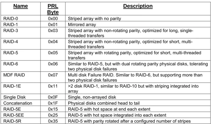
4.1 Primary RAID Level
Table 1 lists values used in the Primary_RAID_Level field of the Virtual Disk Configuration Record (Section 5.9.1) and the definitions of these values. The Primary_RAID_Level field MUST use the values listed in Table 1. The table defines the standard RAID levels, such as RAID 0, 1, 3, 5, etc. and some proprietary RAID types. Non-RAID types such as JBOD and concatenation are also included for completeness.
Table 1: Primary RAID Levels
Name PRL
Byte
Description
RAID-0 0x00 Striped array with no parityRAID-1 0x01 Mirrored array
RAID-3 0x03 Striped array with non-rotating parity, optimized for long, single-threaded transfers
RAID-4 0x04 Striped array with non-rotating parity, optimized for short, multi-threaded transfers
RAID-5 0x05 Striped array with rotating parity, optimized for short, multi-threaded transfers
RAID-6 0x06 Similar to RAID-5, but with dual rotating parity physical disks, tolerating two physical disk failures
MDF RAID 0x07 Multi disk Failure RAID. Similar to RAID-6, but supporting more than two physical disk failures
RAID-1E 0x11 >2 disk RAID-1, similar to RAID-10 but with striping integrated into array
Single Disk 0x0F Single, non-arrayed disk
Concatenation 0x1F Physical disks combined head to tail RAID-5E 0x15 RAID-5 with hot space at end each extent RAID-5EE 0x25 RAID-5 with hot space integrated into each extent
RAID-5R 0x35 RAID-5 with parity rotated after a configured number of stripes
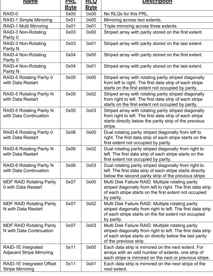
4.2 RAID Level Qualifier
This section defines RAID Level Qualifiers (RLQ) for each Primary RAID Level as defined earlier. The RLQ field MUST be ignored for JBOD and Concatenations (PRL=0F and 1F). Table 2 gives brief descriptions of the RLQs defined for each Primary RAID Level described in this specification. The following subsections describe the data formats defined by the PRLs and the associated RLQs in detail.
Table 2: RAID Level Qualifiers
Name PRL
Byte
RLQ
Byte
Description
RAID-0 0x00 0x00 No RLQs for this PRL.RAID-1 Simple Mirroring 0x01 0x00 Mirroring across two extents.
RAID-1 Multi Mirroring 0x01 0x01 Triple mirroring across three extents. RAID-3 Non-Rotating
Parity 0 0x03 0x00 Striped array with parity stored on the first extent. RAID-3 Non-Rotating
Parity N 0x03 0x01 Striped array with parity stored on the last extent. RAID-4 Non-Rotating
Parity 0
0x04 0x00 Striped array with parity stored on the first extent. RAID-4 Non-Rotating
Parity N 0x04 0x01 Striped array with parity stored on the last extent. RAID-5 Rotating Parity 0
with Data Restart 0x05 0x00 Striped array with rotating parity striped diagonally from left to right. The first data strip of each stripe starts on the first extent not occupied by parity. RAID-5 Rotating Parity N
with Data Restart 0x05 0x02 Striped array with rotating parity striped diagonally from right to left. The first data strip of each stripe starts on the first extent not occupied by parity. RAID-5 Rotating Parity N
with Data Continuation 0x05 0x03 Striped array with rotating parity striped diagonally from right to left. The first data strip of each stripe starts directly below the parity strip of the previous stripe.
RAID-6 Rotating Parity 0 with Data Restart
0x06 0x00 Dual rotating parity striped diagonally from left to right. The first data strip of each stripe starts on the first extent not occupied by parity.
RAID-6 Rotating Parity N
with Data Restart 0x06 0x02 Dual rotating parity striped diagonally from right to left. The first data strip of each stripe starts on the first extent not occupied by parity.
RAID-6 Rotating Parity N
with Data Continuation 0x06 0x03 Dual rotating parity striped diagonally from right to left. The first data strip of each stripe starts directly below the second parity strip of the previous stripe. MDF RAID Rotating Parity
0 with Data Restart
0x07 0x00 Multi Disk Failure RAID. Multiple rotating parity striped diagonally from left to right. The first data strip of each stripe starts on the first extent not occupied by parity.
MDF RAID Rotating Parity N with Data Restart
0x07 0x02 Multi Disk Failure RAID. Multiple rotating parity striped diagonally from right to left. The first data strip of each stripe starts on the fist extent not occupied by parity.
MDF RAID Rotating Parity N with Data Continuation
0x07 0x03 Multi Disk Failure RAID. Multiple rotating parity striped diagonally from right to left. The first data strip of each stripe starts on directly below the last parity of the previous strip.
RAID-1E Integrated
Adjacent Stripe Mirroring 0x11 0x00 Each data strip is mirrored on the next extent. For arrays with an odd number of extents, one strip of each stripe is mirrored on the next or previous stripe. RAID-1E Integrated Offset
Single Disk 0x0F 0x00 No RLQs for this PRL. Concatenation 0x1F 0x00 No RLQs for this PRL. RAID-5E Rotating Parity 0
with Data Restart 0x15 0x00 Same as PRL=05, RLQ=00 with hot space at the end of each extent. RAID-5E Rotating Parity N
with Data Restart 0x15 0x02 Same as PRL=05, RLQ=02 with hot space at the end of each extent. RAID-5E Rotating Parity N
with Data Continuation
0x15 0x03 Same as PRL=05, RLQ=03 with hot space at the end of each extent.
RAID-5EE Rotating Parity
0 with Data Restart 0x25 0x00 Same as PRL=05, RLQ=00 with hot space integrated in to each extent. The hot space of each stripe directly follows the parity block of that stripe.
RAID-5EE Rotating Parity N with Data Restart
0x25 0x02 Same as PRL=05, RLQ=02 with hot space integrated in to each extent. The hot space of each stripe directly precedes the parity block of that stripe. RAID-5EE Rotating Parity
N with Data Continuation 0x25 0x03 Same as PRL=05, RLQ=03 with hot space integrated in to each extent. The hot space of each stripe directly precedes the parity block of that stripe. RAID-5 Rotating Parity 0
after R Stripes with Data Restart
0x35 0x00 Same as PRL=05, RLQ=00 with parity rotated after R stripes instead of every stripe.
RAID-5 Rotating Parity N after R Stripes with Data Restart
0x35 0x02 Same as PRL=05, RLQ=02 with parity rotated after R stripes instead of every stripe.
RAID-5 Rotating Parity N after R Stripes with Data Continuation
0x35 0x03 Same as PRL=05, RLQ=03 with parity rotated after R stripes instead of every stripe.
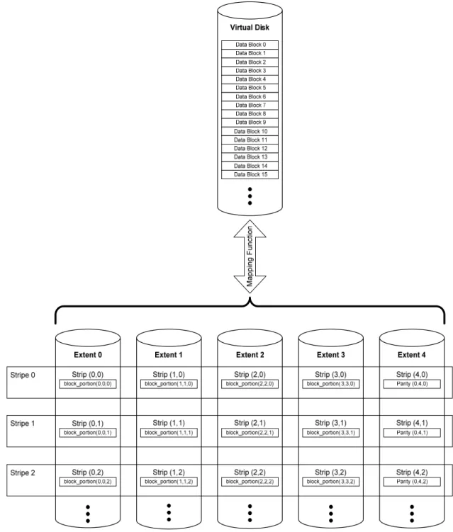
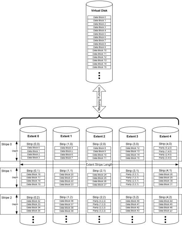
4.2.1 RAID-0 Simple Striping (PRL=00, RLQ=00)
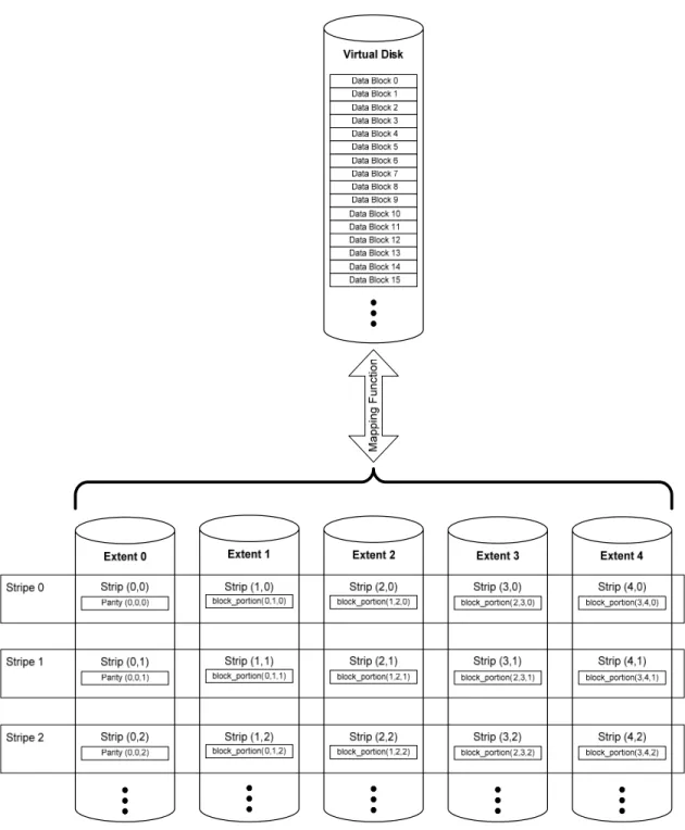
Figure 2 shows an example of simple striping (RAID-0).
Virtual Disk
Data Block 0 Data Block 1 Data Block 2 Data Block 3 Data Block 4 Data Block 5 Data Block 6 Data Block 7 Data Block 8 Data Block 9 Data Block 10 Data Block 11 Data Block 12 Data Block 13 Data Block 14 Data Block 15
Extent 0
Data Block 0 Data Block 1 Data Block 2 Data Block 3
Extent 1
Data Block 4 Data Block 5 Data Block 6 Data Block 7
Extent 2
Data Block 8 Data Block 9 Data Block 10 Data Block 11
Extent 3
Data Block 12 Data Block 13 Data Block 14 Data Block 15
Extent 4
Data Block 16 Data Block 17 Data Block 18 Data Block 19
Stripe 0 Depth
Strip (0,0) Strip (1,0) Strip (2,0) Strip (3,0) Strip (4,0)
Data Block 20 Data Block 21 Data Block 22 Data Block 23
Data Block 24 Data Block 25 Data Block 26 Data Block 27
Data Block 28 Data Block 29 Data Block 30 Data Block 31
Data Block 32 Data Block 33 Data Block 34 Data Block 35
Data Block 36 Data Block 37 Data Block 38 Data Block 39
Stripe 1 Depth
Strip (0,1) Strip (1,1) Strip (2,1) Strip (3,1) Strip (4,1) Extent Stripe Length
M
appi
ng
Functi
on
Data Block 40 Data Block 41 Data Block 42 Data Block 43
Data Block 44 Data Block 45 Data Block 46 Data Block 47
Data Block 48 Data Block 49 Data Block 50 Data Block 51
Data Block 52 Data Block 53 Data Block 54 Data Block 55
Data Block 56 Data Block 57 Data Block 58 Data Block 59
Stripe 2 Depth
Strip (0,2) Strip (1,2) Strip (2,2) Strip (3,2) Strip (4,2)
Figure 2: Simple Striping (PRL=00, RLQ=00) Example
The standard SNIA dictionary definitions for stripe, strip, stripe depth, and extent are used by this example and following examples. For a Basic Virtual Disk (BVD), as defined by this specification, an extent MUST be a contiguous area of a physical disk. A BVD’s extents MUST be of equal size but are not required to reside in the same location of each physical disk.
The example introduces the concept of extent and stripe indices for a strip. strip (i, j) represents the strip
located on extent i in stripe j. The data block index k represents the offset of a given data block from the beginning of a strip. To represent a specific block in a specific extent the following notation is used:
extent_block (k, i, j).
To refer to a specific block in a virtual disk, the following notation is used: virtual_block (x),
where x is the offset from the beginning of the VD.
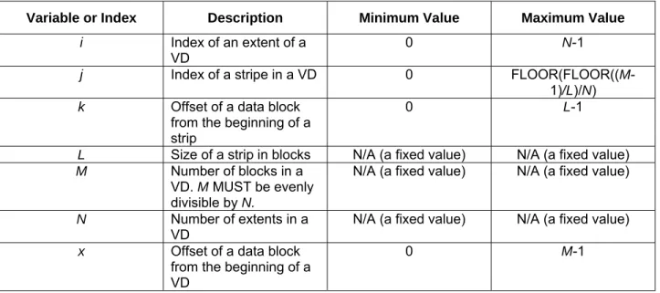
Table 3 summarizes the indices and constants used in the notation along with the any restrictions on legal values.
Table 3: Indices and Constants for Simple Striping
For RAID-0 (PRL=00, RLQ=00), the first strip of the virtual disk MUST be strip (0,0). The allocation of data MUST adhere to the following formula:
Eq. 1
virtual_block (x) = extent_block (MOD(x,L), MOD(FLOOR(x/L), N), FLOOR(FLOOR(x/L)/N)).
Variable or Index Description Minimum Value Maximum Value
i Index of an extent of a
VD 0
N-1
j Index of a stripe in a VD 0 FLOOR(FLOOR((M
-1)/L)/N) k Offset of a data block
from the beginning of a strip
0 L-1
L Size of a strip in blocks N/A (a fixed value) N/A (a fixed value)
M Number of blocks in a VD. M MUST be evenly
divisible by N.
N/A (a fixed value) N/A (a fixed value)
N Number of extents in a
VD N/A (a fixed value) N/A (a fixed value)
x Offset of a data block
from the beginning of a VD
4.2.2 RAID-1 Simple Mirroring (PRL=01, RLQ=00)
A VD with PRL=01 and RLQ=00 MUST have two and only two extents. Each extent MUST be equal to the size of the VD. Each block of the VD, virtual_block(x), MUST be duplicated on both extents at the
same offset
Figure 3 gives an example of simple mirroring.
4.2.3 RAID-1 Multi Mirroring (PRL=01, RLQ=01)
Multi Mirroring (PRL=01, RLQ=01) is a triple mirror. Data MUST be triple copied on three extents. Each virtual_block(x) MUST be duplicated on each extent in the VD. Figure 4 gives an example of multi
mirroring.
4.2.4 RAID-3 Non-Rotating Parity 0 (PRL=03, RLQ=00)
Figure 5 gives an example of RAID-3 with parity contained on the first extent or Non-Rotating Parity 0. Table 4 defines the indices and constants used in the description of RAID-3.
Table 4: Indices and Constants for RAID-3 Non-Rotating Parity
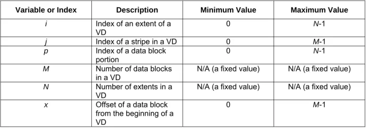
In a RAID-3 VD with N extents, a virtual data block MUST be segmented into N-1 block portions. The
notation for data block portions is:
block_portion (p, i, j)
The allocation of data blocks in a RAID-3 Non-Rotating Parity 0 VD MUST adhere to the following formula:
Eq. 2
virtual_block(x) =
2 0
||
−= N
p
block_portion(p, p+1, x), where || represents the concatenation operator.
Parity blocks MUST reside on extent 0. The values of the parity blocks must adhere to the following formula:
Eq. 3
parity_block (0, 0, x) =
⊕
− =
2
0
N
p
block_portion(p, p+1, x).
The operator ⊕ refers to bit-wise XOR of the operands.
Variable or Index Description Minimum Value Maximum Value
i Index of an extent of a
VD
0 N-1
j Index of a stripe in a VD 0 M-1
p Index of a data block
portion 0
N-1
M Number of data blocks
in a VD N/A (a fixed value) N/A (a fixed value)
N Number of extents in a
VD N/A (a fixed value) N/A (a fixed value)
x Offset of a data block
from the beginning of a VD
4.2.5 RAID-3 Non-Rotating Parity N (PRL=03, RLQ=01)
Figure 6 gives an example of a RAID-3 Non-Rotating Parity N VD. The indices and constants defined in Table 4 are valid for this type of VD.
Figure 6: RAID-3 Non-Rotating Parity N (PRL=03, RLQ=01) Example
The allocation of data blocks in a RAID-3 Non-Rotating Parity N VD MUST adhere to the following formula:
Eq. 4
virtual_block(x) = 2 0
||
−= N
p
block_portion(p, p, x).
Parity Blocks MUST reside on extent N. The allocation of parity blocks MUST adhere to the following
formula:
Eq. 5
parity_block (0, N, x) =
⊕
− =
2
0
N
p
4.2.6 RAID-4 Non-Rotating Parity 0 (PRL=04, RLQ=00)
Figure 7 gives an example of RAID-4 Non-Rotating Parity 0. Table 5 defines the indices and constants used in the description of RAID-4.
Virtual Disk
Data Block 0 Data Block 1 Data Block 2 Data Block 3 Data Block 4 Data Block 5 Data Block 6 Data Block 7 Data Block 8 Data Block 9 Data Block 10 Data Block 11 Data Block 12 Data Block 13 Data Block 14 Data Block 15
Extent 1
Data Block 0 Data Block 1 Data Block 2 Data Block 3
Extent 2
Data Block 4 Data Block 5 Data Block 6 Data Block 7
Extent 3
Data Block 8 Data Block 9 Data Block 10 Data Block 11
Extent 4
Data Block 12 Data Block 13 Data Block 14 Data Block 15
Extent 0 Parity (0,0,0) Parity (1,0,0) Parity (2,0,0) Parity (3,0,0) Stripe 0 Depth
Strip (1,0) Strip (2,0) Strip (3,0) Strip (4,0) Strip (0,0)
Data Block 16 Data Block 17 Data Block 18 Data Block 19
Data Block 20 Data Block 21 Data Block 22 Data Block 23
Data Block 24 Data Block 25 Data Block 26 Data Block 27
Data Block 28 Data Block 29 Data Block 30 Data Block 31 Parity (0,0,1) Parity (1,0,1) Parity (2,0,1) Parity (3,0,1) Stripe 1 Depth
Strip (1,1) Strip (2,1) Strip (3,1) Strip (4,1) Strip (0,1)
Extent Stripe Length
M app in g F unc tion
Data Block 32 Data Block 33 Data Block 34 Data Block 35
Data Block 36 Data Block 37 Data Block 38 Data Block 39
Data Block 40 Data Block 41 Data Block 42 Data Block 43
Data Block 44 Data Block 45 Data Block 46 Data Block 47 Parity (0,0,2) Parity (1,0,2) Parity (2,0,2) Parity (3,0,2) Stripe 2 Depth
Strip (1,2) Strip (2,2) Strip (3,2) Strip (4,2) Strip (0,2)
Table 5: Indices and Constants for RAID 4 Non-Rotating Parity
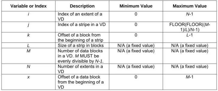
The allocation of data blocks in a Non-Rotating Parity 0 VD MUST adhere to the following equation:
Eq. 6
virtual_block (x) = extent_block (MOD(x,L), MOD(FLOOR(x/L), N-1) +1, FLOOR(FLOOR(x/L)/N-1)).
A parity block contains the parity calculated for N-1 data blocks. The following notation is used to
represent a parity block:
parity_block (k, i, j).
The values of the parity blocks MUST be calculated according to the following formula:
Eq. 7
parity_block (k, 0, j) =
⊕
− =
1
1
N
i
extent_block(k, i, j).
For Non-Rotating Parity 0, all parity blocks MUST reside on extent 0. Thus, i MUST equal zero for all parity blocks.
Variable or Index Description Minimum Value Maximum Value
i Index of an extent of a
VD
0 N-1
j Index of a stripe in a VD 0 FLOOR(FLOOR((M -1)/L)/N-1) k Offset of a block from
the beginning of a strip 0 L-1
L Size of a strip in blocks N/A (a fixed value) N/A (a fixed value) M Number of data blocks
in a VD. M MUST be
evenly divisible by N-1.
N/A (a fixed value) N/A (a fixed value)
N Number of extents in a
VD N/A (a fixed value) N/A (a fixed value)
x Offset of a data block
from the beginning of a VD
4.2.7 RAID-4 Non-Rotating Parity N (PRL=04, RLQ=01)
Figure 8gives an example on Non-Rotating Parity N (a.k.a. RAID-4). Non-Rotating Parity N differs from Non-Rotating Parity 0 in that the parity is stored in the last extent of a VD. The indices and constants of Table 5 are valid for Non-Rotating Parity N.
Extent 0
Virtual Disk
Data Block 0 Data Block 1 Data Block 2 Data Block 3 Data Block 4 Data Block 5 Data Block 6 Data Block 7 Data Block 8 Data Block 9 Data Block 10 Data Block 11 Data Block 12 Data Block 13 Data Block 14 Data Block 15
Data Block 0 Data Block 1 Data Block 2 Data Block 3
Extent 1
Data Block 4 Data Block 5 Data Block 6 Data Block 7
Extent 2
Data Block 8 Data Block 9 Data Block 10 Data Block 11
Extent 3
Data Block 12 Data Block 13 Data Block 14 Data Block 15
Extent 4 Parity (0,4,0) Parity (1,4,0) Parity (2,4,0) Parity (3,4,0) Stripe 0 Depth
Data Block 16 Data Block 17 Data Block 18 Data Block 19
Data Block 20 Data Block 21 Data Block 22 Data Block 23
Data Block 24 Data Block 25 Data Block 26 Data Block 27
Data Block 28 Data Block 29 Data Block 30 Data Block 31
Parity (0,4,1) Parity (1,4,1) Parity (2,4,1) Parity (3,4,1) Stripe 1 Depth
Extent Stripe Length
Mapping Functi
on
Data Block 32 Data Block 33 Data Block 34 Data Block 35
Data Block 36 Data Block 37 Data Block 38 Data Block 39
Data Block 40 Data Block 41 Data Block 42 Data Block 43
Data Block 44 Data Block 45 Data Block 46 Data Block 47
Parity (0,4,2) Parity (1,4,2) Parity (2,4,2) Parity (3,4,2) Stripe 2 Depth
Strip (1,0) Strip (2,0) Strip (3,0) Strip (4,0) Strip (0,0)
Strip (1,1) Strip (2,1) Strip (3,1) Strip (4,1) Strip (0,1)
Strip (1,2) Strip (2,2) Strip (3,2) Strip (4,2) Strip (0,2)
Figure 8: Non-Rotating Parity N (PRL=04, RLQ=01) Example
Eq. 8
virtual_block (x) = extent_block (MOD(x,L), MOD(FLOOR(x/L), N-1), FLOOR(FLOOR(x/L)/N-1)). The values of the parity blocks MUST be calculated according to the following formula:
Eq. 9
parity_block (k, N-1, j) =
⊕
− =
2
0
N
i
extent_block(k, i, j).
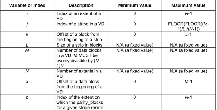
4.2.8 RAID-5 Rotating Parity 0 with Data Restart (PRL=05, RLQ=00)
Figure 9 gives an example of Rotating Parity 0 with Data Restart. Rotating Parity 0 with Data Restart is an implementation of RAID-5. Table 6 defines the indices and constants used in the description of RAID-5.
Map
pin
g F
unct
ion
Table 6: Indices and Constants for RAID-5 Rotating Parity 0 and N
The extent p on which the parity block for a given virtual block x resides MUST adhere to the following
formula:
Eq. 10
p = MOD(FLOOR(FLOOR(x/L)/(N-1)),N).
The extent i on which a given virtual block x resides MUST adhere to the following formula:
Eq. 11
IF MOD(FLOOR(x/L),N-1) < p
THEN i = MOD(FLOOR(x/L),N-1)
ELSE i = MOD(FLOOR(x/L),N-1)+1.
The allocation of data blocks in a Rotating Parity 0 with Data Restart VD MUST adhere to the following formula:
Eq. 12
virtual_block (x) = extent_block (MOD(x/L), i, FLOOR(FLOOR(x/L)/(N-1))
The values of the parity blocks MUST be calculated according to the following formula:
Variable or Index Description Minimum Value Maximum Value
i Index of an extent of a
VD
0 N-1
j Index of a stripe in a VD 0 FLOOR(FLOOR((M -1)/L)/(N-1)) k Offset of a block from
the beginning of a strip 0 L-1
L Size of a strip in blocks N/A (a fixed value) N/A (a fixed value) M Number of data blocks
in a VD. M MUST be
evenly divisible by ( N-1)*L
N/A (a fixed value) N/A (a fixed value)
N Number of extents in a
VD N/A (a fixed value) N/A (a fixed value)
x Offset of a data block
from the beginning of a VD
0 M-1
p Index of the extent on which the parity_blocks for a given stripe reside
Eq. 13
parity_block (k, p, j) =
⊕
≠ −
=
p i N
i
, 1
0
4.2.9 RAID-5 Rotating Parity N with Data Restart (PRL=05, RLQ=02)
Figure 10 gives an example of an implementation of RAID-5 called Rotating Parity N with Data Restart. The indices and constants listed in Table 6 are valid for this type of RAID.
Figure 10: Rotating Parity N with Data Restart (PR=05, RLQ=02) Example
The extent p on which the parity block for a given virtual block x resides MUST adhere to the following
Eq. 14
p = (N-1)-MOD(FLOOR(FLOOR(x/L)/(N-1)),N).
The extent i on which a given virtual block x resides MUST adhere to the following formula:
Eq. 15
IF MOD(FLOOR(x/L),N-1) < p
THEN i = MOD(FLOOR(x/L),N-1)
ELSE i = MOD(FLOOR(x/L),N-1)+1.
The allocation of data blocks in a Rotating Parity N with Data Restart VD MUST adhere to the following formula:
Eq. 16
virtual_block (x) = extent_block (MOD(x/L), i, FLOOR(FLOOR(x/L)/(N-1))
The values of the parity blocks MUST be calculated according to the following formula:
Eq. 17
parity_block (k, p, j) =
⊕
≠ −
=
p i N
i
, 1
0
4.2.10 RAID-5 Rotating Parity N with Data Continuation (PRL=05, RLQ=03)
Figure 11 gives an example of RAID-5 implemented with Rotating Parity N with Data Continuation. The indices and constants given in Table 6 also apply to the formulas given below for Rotating Parity N with Data Continuation.
Extent 0
Virtual Disk
Data Block 0 Data Block 1 Data Block 2 Data Block 3 Data Block 4 Data Block 5 Data Block 6 Data Block 7 Data Block 8 Data Block 9 Data Block 10 Data Block 11 Data Block 12 Data Block 13 Data Block 14 Data Block 15
Data Block 0 Data Block 1 Data Block 2 Data Block 3
Extent 1
Data Block 4 Data Block 5 Data Block 6 Data Block 7
Extent 2
Data Block 8 Data Block 9 Data Block 10 Data Block 11
Extent 3
Data Block 12 Data Block 13 Data Block 14 Data Block 15
Extent 4 Stripe 0
Depth
Data Block 16 Data Block 17 Data Block 18 Data Block 19 Data Block 20
Data Block 21 Data Block 22 Data Block 23
Data Block 24 Data Block 25 Data Block 26 Data Block 27
Data Block 28 Data Block 29 Data Block 30 Data Block 31
Stripe 1
Depth
Extent Stripe Length
Mappi
ng Fun
cti
on
Data Block 32 Data Block 33 Data Block 34 Data Block 35
Data Block 36 Data Block 37 Data Block 38 Data Block 39 Data Block 40
Data Block 41 Data Block 42 Data Block 43
Data Block 44 Data Block 45 Data Block 46 Data Block 47
Stripe 2
Depth
Strip (0,0)
Strip (0,1)
Strip (0,2)
Strip (1,0) Strip (2,0) Strip (3,0) Strip (4,0)
Strip (1,1) Strip (2,1) Strip (3,1) Strip (4,1)
Strip (1,2) Strip (2,2) Strip (3,2) Strip (4,2)
Parity (0,4,0) Parity (1,4,0) Parity (2,4,0) Parity (3,4,0) Parity (0,3,1) Parity (1,3,1) Parity (2,3,1) Parity (3,3,1) Parity (0,2,2) Parity (1,2,2) Parity (2,2,2) Parity (3,2,2)
The extent p on which the parity block for a given virtual block x resides MUST adhere to the following
formula:
Eq. 18
p = (N-1)-MOD(FLOOR(FLOOR(x/L)/(N-1)),N).
The extent i on which a given virtual block x resides MUST adhere to the following formula:
Eq. 19
i = MOD(MOD(FLOOR(x/L),(N-1))+p+1),N).
The allocation of data blocks in a Rotating Parity N with Data Continuation VD MUST adhere to the following formula:
Eq. 20
virtual_block (x) = extent_block (MOD(x/L), i, FLOOR(FLOOR(x/L)/(N-1))
The values of the parity blocks MUST be calculated according to the following formula:
Eq. 21
parity_block (k, p, j) =
⊕
≠ −
=
p i N
i
, 1
0
4.2.11 RAID-5E Rotating Parity 0 with Data Restart (PRL=15, RLQ=00)
Figure 12 gives an example of RAID-5E implemented with Rotating Parity 0 with Data Restart.
Ma
pp
ing
Fu
nc
tion
RAID-5E has hot space at the end of each extent. In the event of an extent failure, the hot space on the remaining extents is used to rebuild and re-stripe the data in a manner that the remaining extents become a RAID-5 VD.
Table 7 gives the indices and constants used to describe the data layout of this type of RAID in the
following formulas.
Table 7: Indices and Constants for RAID-5E
The extent p on which the parity block for a given virtual block x resides MUST adhere to the following
formula:
Eq. 22
p = MOD(FLOOR(FLOOR(x/L)/(N-1)),N).
The extent i on which a given virtual block x resides MUST adhere to the following formula:
Eq. 23
IF MOD(FLOOR(x/L),N-1) < p
THEN i = MOD(FLOOR(x/L),N-1)
ELSE i = MOD(FLOOR(x/L),N-1)+1.
The allocation of data blocks in a RAID-5E Rotating Parity 0 with Data Restart VD MUST adhere to the following formula:
Variable or Index Description Minimum Value Maximum Value
i Index of an extent of a
VD 0
N-1
j Index of a stripe in a VD 0 FLOOR(FLOOR((M
-1)/L)/(N-1)) k Offset of a block from
the beginning of a strip 0 L-1
L Size of a strip in blocks N/A (a fixed value) N/A (a fixed value) M Number of data blocks
in a VD. M MUST be evenly divisible by ( N-1)*L
N/A (a fixed value) N/A (a fixed value)
N Number of extents in a
VD N/A (a fixed value) N/A (a fixed value)
x Offset of a data block
from the beginning of a VD
0 M-1
p Index of the extent on
which the parity_blocks for a given stripe reside
0 N-1
U Number of hot space
blocks ≥ ((M/(N-1)) * N) - M ≥ ((M/(N-1)) * N) - M
W Index of the last stripe
containing data blocks FLOOR(FLOOR((
M -1)/L)/(N-1))
FLOOR(FLOOR((M -1)/L)/(N-1))
Eq. 24
virtual_block (x) = extent_block (MOD(x/L), i, FLOOR(FLOOR(x/L)/(N-1)) The values of the parity blocks MUST be calculated according to the following formula:
Eq. 25
parity_block (k, p, j) =
⊕
≠ −
=
p i N
i
, 1
0
extent_block (k, i, j).
The number of hot space blocks U MUST adhere to the following formula:
Eq. 26
U ≥ ((M/(N-1)) * N) - M
Hot space blocks MUST begin at offset M from the beginning of the VD. The total number of blocks in the
VD MUST equal M+U. The hot space blocks MUST be evenly distributed across all extents. All hot space
blocks on an extent MUST reside at the end of the extent.
In the event of an extent failure, the controller MUST reallocate the data as described in Section 4.2.8. The number of extents used in the resulting RAID-5 VD MUST be equal to the number of extents used in the RAID-5E VD reduced by one.
4.2.12 RAID-5E Rotating Parity N with Data Restart (PRL=15, RLQ=02)
Figure 13 gives an example of a RAID-5E implementation utilizing Rotating Parity N with Data Restart. The indices and constants listed in Table 7 are valid for this type of RAID.
The extent p on which the parity block for a given virtual block x resides MUST adhere to the following formula:
Eq. 27
p = (N-1)-MOD(FLOOR(FLOOR(x/L)/(N-1)),N).
The extent i on which a given virtual block x resides MUST adhere to the following formula:
Eq. 28
IF MOD(FLOOR(x/L),N-1) < p
THEN i = MOD(FLOOR(x/L),N-1)
ELSE i = MOD(FLOOR(x/L),N-1)+1.
The allocation of data blocks in a RAID-5E Rotating Parity N with Data Restart VD MUST adhere to the following formula:
Eq. 29
virtual_block (x) = extent_block (MOD(x/L), i, FLOOR(FLOOR(x/L)/(N-1))
The values of the parity blocks MUST be calculated according to the following formula:
Eq. 30
parity_block (k, p, j) =
⊕
≠ −
=
p i N
i
, 1
0
extent_block (k, i, j).
The number of hot space blocks U MUST adhere to the following formula:
Eq. 31
U ≥ ((M/(N-1)) * N) - M
Hot space blocks MUST begin at offset M from the beginning of the VD. The total number of blocks in the
VD MUST equal M+U. The hot space blocks MUST be evenly distributed across all extents. All hot space
blocks on an extent MUST reside at the end of the extent.
In the event of an extent failure, the controller MUST reallocate the data as described in Section 4.2.9. The number of extents used in the resulting RAID-5 VD MUST be equal to the number of extents used in the RAID-5E VD reduced by one.
4.2.13 RAID-5E Rotating Parity N with Data Continuation (PRL=15, RLQ=03)
Figure 14 gives an example of a RAID-5E volume implemented utilizing Rotating Party N with Data Continuation. The indices and constants listed in Table 7 are valid for this type of RAID.
The extent p on which the parity block for a given virtual block x resides MUST adhere to the following formula:
Eq. 32
p = (N-1)-MOD(FLOOR(FLOOR(x/L)/(N-1)),N).
The extent i on which a given virtual block x resides MUST adhere to the following formula:
Eq. 33
i = MOD(MOD(FLOOR(x/L),(N-1))+p+1),N).
The allocation of data blocks in a RAID-5E Rotating Parity N with Data Continuation VD MUST adhere to the following formula:
Eq. 34
virtual_block (x) = extent_block (MOD(x/L), i, FLOOR(FLOOR(x/L)/(N-1))
The values of the parity blocks MUST be calculated according to the following formula:
Eq. 35
parity_block (k, p, j) =
⊕
≠ −
=
p i N
i
, 1
0
extent_block (k, i, j).
The number of hot space blocks U MUST adhere to the following formula:
Eq. 36
U ≥ ((M/(N-1)) * N) - M
Hot space blocks MUST begin at offset M from the beginning of the VD. The total number of blocks in the VD MUST equal M+U. The hot space blocks MUST be evenly distributed across all extents. All hot space
blocks on an extent MUST reside at the end of the extent.
In the event of an extent failure, the controller MUST reallocate the data as described in Section 4.2.10. The number of extents used in the resulting RAID-5 VD MUST be equal to the number of extents used in the RAID-5E VD reduced by one.
4.2.14 RAID-5EE Rotating Parity 0 with Data Restart (PRL=25, RLQ=00)
Figure 15 gives an example of 5EE implemented with Rotating Parity 0 with Data Restart. RAID-5EE has hot space distributed across the extents. In the event of an extent failure, the hot space on the remaining extents is used to rebuild and re-stripe the data in a manner that the remaining extents become a RAID-5 VD. Table 8 gives the indices and constants used to describe the data layout of this type of RAID.
Table 8: Indices and Constants for RAID-5EE
The stripe j on which a given virtual block x resides MUST adhere to the following formula:
Eq. 37
j = FLOOR(FLOOR(x/L)/(N-2))
The extent p on which the parity for a given stripe j resides MUST adhere to the following formula:
Eq. 38
p = MOD(j,N).
The extent h on which hot space for a given stripe j resides MUST adhere to the following formula:
Eq. 39
h = MOD((p+1),N).
The extent i on which a given virtual block x resides MUST adhere to the following formula:
Eq. 40
IF MOD(FLOOR(x/L),N-2) < p
THEN
IF MOD(FLOOR(x/L),N-2) < h
Variable or Index Description Minimum Value Maximum Value
i Index of an extent of a
VD
0 N-1
j Index of a stripe in a VD 0 FLOOR(FLOOR(M -1/L)/(N-2)) k Offset of a block from
the beginning of a strip 0 L-1
L Size of a strip in blocks N/A (a fixed value) N/A (a fixed value) M Number of data blocks
in a VD. M MUST be
evenly divisible by ( N-2)*L
N/A (a fixed value) N/A (a fixed value)
N Number of extents in a
VD N/A (a fixed value) N/A (a fixed value)
x Offset of a data block
from the beginning of a VD
0 M-1
p Index of the extent on which the parity_blocks for a given stripe reside
0 N-1
h Index of the extent on
which the hot space for a given stripe resides
THEN
i = MOD(FLOOR(x/L),N-2) ELSE
i = MOD(FLOOR(x/L),N-2)+1
ELSE
i = MOD(FLOOR(x/L,1),N-2)+2
The allocation of data blocks in a RAID-5EE Rotating Parity 0 with Data Restart VD MUST adhere to the following formula:
Eq. 41
virtual_block(x) = extent_block(MOD(x/L), i, j)
The values of the party blocks MUST be calculated according to the following formula:
Eq. 42
In the event of an extent failure, the controller MUST reallocate the data as describe in Section 4.2.8. The number of extents used in the resulting RAID-5 VD MUST be equal to the number of extents used in the RAID-5EE volume reduced by one.
4.2.15 RAID-5EE Rotating Parity N with Data Restart (PRL=25, RLQ=02)
Figure 16 gives an example of RAID-5EE implemented with Rotating Parity N with Data Restart. The indices and constants given in Table 8 are used in the description below.
M
a
pp
in
g F
unc
tio
n
Figure 16: RAID-5EE Rotating Parity N with Data Restart (PRL=25, RLQ=02) Example
Eq. 43
j = FLOOR(FLOOR(x/L)/(N-2)).
The extent p on which the parity for a given stripe j resides MUST adhere to the following formula:
Eq. 44
p = (N-1) - MOD(j,N).
The extent h on which hot space for a given stripe j resides MUST adhere to the following formula:
Eq. 45
h = MOD((p-1),N).
The extent i on which a given virtual block x resides MUST adhere to the following formula:
Eq. 46
IF MOD(FLOOR(x/L),N-2) < h
THEN
IF MOD(FLOOR(x/L),N-2) < p
THEN
i = MOD(FLOOR(x/L),N-2)
ELSE
i = MOD(FLOOR(x/L),N-2)+1
ELSE
i = MOD(FLOOR(x/L,1),N-2)+2
The allocation of data blocks in a RAID-5EE Rotating Parity N with Data Restart VD MUST adhere to the following formula:
Eq. 47
virtual_block(x) = extent_block(MOD(x/L), i, j).
The values of the party blocks MUST be calculated according to the following formula:
In the event of an extent failure, the controller MUST reallocate the data as describe in Section 4.2.9. The number of extents used in the resulting RAID-5 VD MUST be equal to the number of extents used in the RAID-5EE volume reduced by one.
4.2.16 RAID-5EE Rotating Parity N with Data Continuation (PRL=25, RLQ=03)
Figure 17 gives an example of RAID-5EE implemented with Rotating Party N with Data Continuation. The indices and constants given in Table 8 are used in the description below.
Extent 0
Virtual Disk
Data Block 0 Data Block 1 Data Block 2 Data Block 3 Data Block 4 Data Block 5 Data Block 6 Data Block 7 Data Block 8 Data Block 9 Data Block 10 Data Block 11 Data Block 12 Data Block 13 Data Block 14 Data Block 15
Extent 1
Data Block 0 Data Block 1 Data Block 2 Data Block 3
Extent 2
Data Block 4 Data Block 5 Data Block 6 Data Block 7
Extent 3
Data Block 8 Data Block 9 Data Block 10 Data Block 11
Extent 4 Parity (0,4,0) Parity (1,4,0) Parity (2,4,0) Parity (3,4,0) Stripe 0 Depth
Data Block 12 Data Block 13 Data Block 14 Data Block 15 Data Block 16
Data Block 17 Data Block 18 Data Block 19
Data Block 20 Data Block 21 Data Block 22 Data Block 23
HS Block 4 HS Block 5 HS Block 6 HS Block 7
Parity (0,3,1) Parity (1,3,1) Parity (2,3,1) Parity (3,3,1) Stripe 1 Depth
Extent Stripe Length
Mapping Function
Data Block 32 Data Block 33 Data Block 34 Data Block 35
HS Block 8 HS Block 9 HS Block 10 HS Block 11
Data Block 28 Data Block 29 Data Block 30 Data Block 31 Parity (0,2,2) Parity (1,2,2) Parity (2,2,2) Parity (3,2,2) Stripe 2 Depth Strip (0,0) Strip (0,1) Strip (0,2)
Strip (1,0) Strip (2,0) Strip (3,0) Strip (4,0)
Strip (1,1) Strip (2,1) Strip (3,1) Strip (4,1)
Strip (1,2) Strip (2,2) Strip (3,2) Strip (4,2)
HS Block 0 HS Block 1 HS Block 2 HS Block 3
Data Block 24 Data Block 25 Data Block 26 Data Block 27
The strip j on which a given virtual block x resides MUST adhere to the following formula:
Eq. 49
j = FLOOR(FLOOR(x/L)/(N-2)).
The extent p on which the parity for a given stripe j resides MUST adhere to the following formula:
Eq. 50
p = (N-1) - MOD(j,N).
The extent h on which hot space for a given stripe j resides MUST adhere to the following formula:
Eq. 51
h = MOD((p-1),N).
The extent i on which a given virtual block x resides MUST adhere to the following formula:
Eq. 52
i = MOD(MOD(FLOOR(x/L),N-2)+p+1,N).
The allocation of data blocks in a RAID-5EE Rotating Parity N with Data Restart VD MUST adhere to the following formula:
Eq. 53
virtual_block(x) = extent_block(MOD(x/L), i, j).
The values of the party blocks MUST be calculated according to the following formula:
Eq. 54
In the event of an extent failure, the controller MUST reallocate the data as describe in Section 4.2.10. The number of extents used in the resulting RAID-5 VD MUST be equal to the number of extents used in the RAID-5EE volume reduced by one.
4.2.17 RAID-5R Rotating Parity 0 after R Stripes with Data Restart (PRL=35, RLQ=00)
Figure 18 gives an example of RAID-5R Rotating Parity 0 after R Stripes with Data Restart. Table 9 gives the indices and constants used to describe the data layout of this type of RAID in the following formulas.
Table 9: Indices and Constants for RAID-5R Rotating Parity 0 and N
The extent p on which the parity block for a given virtual block x resides MUST adhere to the following
formula:
Eq. 55
p = MOD(FLOOR(FLOOR(x/(L*R))/(N-1)),N).
The extent i on which a given virtual block x resides MUST adhere to the following formula:
Eq. 56
IF MOD(FLOOR(x/(L*R)),N-1) < p
THEN i = MOD(FLOOR(x/(L*R)),N-1)
ELSE i = MOD(FLOOR(x/(L*R)),N-1)+1.
The allocation of data blocks in a Rotating Parity 0 with Data Restart VD MUST adhere to the following formula:
Eq. 57
virtual_block (x) = extent_block (MOD(x,L), i, FLOOR(FLOOR(x/L)/(N-1))
The values of the parity blocks MUST be calculated according to the following formula:
Variable or Index Description Minimum Value Maximum Value
i Index of an extent of a
VD
0 N-1
j Index of a stripe in a VD 0 FLOOR(FLOOR((M -1)/L)/(N-1)) k Offset of a block from
the beginning of a strip 0 L-1
L Size of a strip in blocks N/A (a fixed value) N/A (a fixed value) M Number of data blocks
in a VD. M MUST be
evenly divisible by ( N-1)*L*R
N/A (a fixed value) N/A (a fixed value)
N Number of extents in a
VD N/A (a fixed value) N/A (a fixed value)
R Number of stripes
before rotating Parity (where R=2^n)
1 (default) 0x80000000
x Offset of a data block
from the beginning of a VD
0 M-1
p Index of the extent on
which the parity_blocks for a given stripe reside
Eq. 58
parity_block (k, p, j) =
⊕
≠ −
=
p i N
i
, 1
0
4.2.18 RAID-5R Rotating Parity N after R Stripes with Data Restart (PRL=35, RLQ=02)
Figure 19 gives an example of an implementation of RAID-5 Rotating Parity N after R Stripes with Data Restart. The indices and constants listed in Table 9 are valid for this type of RAID.
Extent 0
Virtual Disk
Data Block 0 Data Block 1 Data Block 2 Data Block 3 Data Block 4 Data Block 5 Data Block 6 Data Block 7 Data Block 8 Data Block 9 Data Block 10 Data Block 11 Data Block 12 Data Block 13 Data Block 14 Data Block 15
Extent 1 Extent 2 Extent 3 Extent 4
Stripe 0
Depth
Strip (0,0) Strip (1,0) Strip (2,0) Strip (3,0) Strip (4,0)
Data Block 16 Data Block 17 Data Block 18 Data Block 19
Data Block 24 Data Block 25 Data Block 26 Data Block 27
Data Block 28 Data Block 29 Data Block 30 Data Block 31
Parity (0,4,1) Parity (1,4,1) Parity (2,4,1) Parity (3,4,1) Stripe 1 Depth
Strip (0,1) Strip (1,1) Strip (2,1) Strip (3,1) Strip (4,1) Extent Stripe Length
Data Block 32 Data Block 33 Data Block 34 Data Block 35
Data Block 36 Data Block 37 Data Block 38 Data Block 39
Parity (0,3,2) Parity (1,3,2) Parity (2,3,2) Parity (3,3,2)
Data Block 44 Data Block 45 Data Block 46 Data Block 47
Stripe 2
Depth
Strip (1,2) Strip (2,2) Strip (3,2) Strip (4,2) Strip (0,2)
Data Block 4 Data Block 5 Data Block 6 Data Block 7
Data Block 8 Data Block 9 Data Block 10 Data Block 11
Data Block 12 Data Block 13 Data Block 14 Data Block 15
Parity (0,4,0) Parity (1,4,0) Parity (2,4,0) Parity (3,4,0) Data Block 0
Data Block 1 Data Block 2 Data Block 3
Data Block 20 Data Block 21 Data Block 22 Data Block 23
Data Block 40 Data Block 41 Data Block 42 Data Block 43
Data Block 48 Data Block 49 Data Block 50 Data Block 51
Data Block 56 Data Block 57 Data Block 58 Data Block 59
Parity (0,3,3) Parity (1,3,3) Parity (2,3,3) Parity (3,3,3)
Data Block 60 Data Block 61 Data Block 62 Data Block 63
Stripe 3
Depth
Strip (0,3) Strip (1,3) Strip (2,3) Strip (3,3) Strip (4,3)
Data Block 64 Data Block 65 Data Block 66 Data Block 67
Data Block 68 Data Block 69 Data Block 70 Data Block 71
Data Block 72 Data Block 73 Data Block 74 Data Block 75
Data Block 76 Data Block 77 Data Block 78 Data Block 79
Stripe 4
Depth
Strip (1,4) Strip (2,4) Strip (3,4) Strip (4,4) Strip (0,4)
Data Block 52 Data Block 53 Data Block 54 Data Block 55
Parity (0,2,4) Parity (1,2,4) Parity (2,2,4) Parity (3,2,4)
The extent p on which the parity block for a given virtual block x resides MUST adhere to the following
formula:
Eq. 59
p = (N-1)-MOD(FLOOR(FLOOR(x/(L*R))/(N-1)),N).
The extent i on which a given virtual block x resides MUST adhere to the following formula:
Eq. 60
IF MOD(FLOOR(x/(L*R)),N-1) < p
THEN i = MOD(FLOOR(x/(L*R)),N-1)
ELSE i = MOD(FLOOR(x/(L*R)),N-1)+1.
The allocation of data blocks in a Rotating Parity N with Data Restart VD MUST adhere to the following formula:
Eq. 61
virtual_block (x) = extent_block (MOD(x,L), i, FLOOR(FLOOR(x/L)/(N-1))
The values of the parity blocks MUST be calculated according to the following formula:
Eq. 62
parity_block (k, p, j) =
⊕
≠ −
=
p i N
i
, 1
0
4.2.19 RAID-5R Rotating Parity N after R Stripes with Data Continuation (PRL=35,
RLQ=03)
Figure 20 gives an example of RAID-5 Rotating Parity N after R Stripes with Data Continuation. The indices and constants given in Table 9 also apply to the formulas given below.