Version
8.1
|
June 2013
|
3725-74602-100
Polycom® RealPresence® Collaboration Server
800s, Virtual Edition Getting Started Guide
© 2013 Polycom, Inc. All rights reserved. Polycom, Inc.
6001 America Center Drive San Jose CA 95002 USA
No part of this document may be reproduced or transmitted in any form or by any means, electronic or mechanical, for any purpose, without the express written permission of Polycom, Inc. Under the law, reproducing includes translating into another language or format.
marks of Polycom, Inc., and are registered and/or common law marks in the United States and various other countries.
All other trademarks are the property of their respective owners.
Patent Information
The accompanying product may be protected by one or more U.S. and foreign patents and/or pending patent applications held by Polycom, Inc.
This document provides the latest information for security-conscious users running Version 8.1 software. The information in this document is not intended to imply that DoD or DISA certifies Polycom RealPresence Collaboration Server systems.
End User License Agreement
Use of this software constitutes acceptance of the terms and conditions of the Polycom® RealPresence® Collaboration Server 800s, Virtual Edition system end-user license agreements (EULA).
The EULA for your version is available on the Polycom Support page for the Polycom® RealPresence® Collaboration Server 800s, Virtual Edition system.
Table of Contents
System Overview . . . 1-1
About the Polycom RealPresence Collaboration Server 800s Getting Started Guide .. 1-1 Prerequisites ... 1-1 Who Should Read This Guide? ... 1-2 How This Guide is Organized ... 1-2 About the Polycom RealPresence Collaboration Server 800s System ... 1-3 RealPresence Collaboration Server Main Features ... 1-4 Conferencing Modes ... 1-4 AVC-based Video Session Types ... 1-5 Dynamic Continuous Presence ... 1-5 Operator Conference ... 1-5 AVC-based Video Resolutions ... 1-5 Resolution Configuration for AVC-based CP Conferences ... 1-5 SVC-based Conferencing ... 1-6 H.239 ... 1-6 IVR-Enabled Conferencing ... 1-6 Entry Queue ... 1-6 Conferencing Capabilities and Options ... 1-7 On Demand Conferencing ... 1-7 Permanent Conference ... 1-7 Scheduled Conferencing / Reservations ... 1-7 Polycom Conferencing for Microsoft Outlook® (AVC-basedConferencing) ... 1-7 Connection Methods ... 1-8 Cascading Conferences (AVC-based Conferencing) ... 1-8 Security ... 1-8 LAN Redundancy ... 1-9 Conference Management and Monitoring Features ... 1-9 CP AVC-based and SVC-based Conferencing ... 1-9 CP AVC-based Conferencing ... 1-9 Workstation Requirements ... 1-10 Microsoft Windows 7™ Security Settings ... 1-10 Internet Explorer 8 Configuration ... 1-12
First Time Installation and Configuration . . . 2-1
Preparations ... 2-1 Gather Network Equipment and Address Information ... 2-1 IP Services ... 2-1 Management Network ... 2-2 Default IP Service (Conferencing Service) ... 2-2 IP Network Services Required Information ... 2-2 Installing the RealPresence Collaboration Server 800s ... 2-3Hardware Installation and Rack Mounting ...2-4 Connecting the Cables to the MCU ...2-5 Modifying the Factory Default Management Network Settings on the USB
Memory Stick ...2-5 First Entry Power-up and Configuration ...2-8 Procedure 1: First-time Power-up ...2-8 Procedure 2: Product Registration ...2-8 Obtaining the Activation Key ...2-9 Procedure 3: Connection to MCU ...2-9 Procedure 4: Modifying the Default IP Service Settings ...2-11 Fast Configuration Wizard ...2-11 Selecting the Collaboration Server Web Client Languages ...2-21 RealPresence Collaboration Server 800s Default Conferencing Settings ...2-22
Customizing the RealPresence Collaboration Server 800s Default
Conferencing Settings ...2-24
Basic Operation . . . 3-1
Starting the Collaboration Server Web Client ...3-1 Collaboration Server Web Client Screen Components ...3-2 Viewing and System Functionality Permissions ...3-3 Conferences List ...3-4 List Pane ...3-4 RealPresence Collaboration Server Management Pane ...3-5 Status Bar ...3-5 System Alerts ...3-5 Participant Alerts ...3-6 Port Usage Gauges ...3-6 MCU State ...3-7 Address Book ...3-7 Displaying and Hiding the Address Book ...3-8 Conference Templates ...3-8 Displaying and Hiding Conference Templates ...3-9 Customizing the Main Screen ...3-9 Increasing and Decreasing the Text Size ...3-10 Customizing the RealPresence Collaboration Server Management Pane ....3-10 Starting a Conference ...3-12 Starting an AVC CP Conference from the Conferences Pane ...3-12 General Tab ...3-14 Participants Tab ...3-16 Information Tab ...3-19 Starting a Mixed CP and SVC or SVC Only Conference from the Conferences Pane ...3-21Starting a Meeting from Microsoft Outlook using the Polycom Conferencing Add-in to Microsoft Outlook (AVC CP Only Conferencing) ... 3-26
Starting an Audio Meeting from a Microsoft Outlook Polycom Meeting Invitation ... 3-26 Connecting to a Conference ... 3-27 Direct Dial-in to the MCU ... 3-27
H.323 Participants (AVC CP Only and Mixed CP and SVC
Conferencing) ... 3-28 SIP Participants (AVC CP, Mixed CP and SVC and SVC Conferencing) ... 3-28 Entry Queue Access (AVC Participants) ... 3-29 H.323 Participants (AVC Participants) ... 3-29 SIP Participants (AVC Participants) ... 3-30 Connecting to a Polycom Conference from an Outlook Meeting Invitation
(AVC Only Conferencing) ... 3-31 Dial-out Participants (AVC CP Only and Mixed CP and SVC Conferencing) .... 3-31 Automatic Dial Out ... 3-31 Indications in the Video Layout ... 3-32 Site Names ... 3-32 Displaying and Hiding Site Names ... 3-33 Transparent Site Names ... 3-34 Permanent Display of Site Names ... 3-34 Location of Site Names ... 3-34 Obtaining the Display Name from the Address Book ... 3-34 Message Overlay for Text Messaging (AVC Only) ... 3-35 Network Quality Indication ... 3-35 Network Quality Levels ... 3-36 Guidelines ... 3-36 Monitoring Ongoing Conferences ... 3-37 General Monitoring ... 3-37 Multi Selection ... 3-37 Using the Chairperson Password for Filtering ... 3-38 Conference Level Monitoring ... 3-38 Audio Only Message (AVC CP Only) ... 3-41 Secured Conference Monitoring (AVC CP Only) ... 3-41 Participant Level Monitoring ... 3-41 Participant Connection Monitoring (AVC and SVC-based Connections) ... 3-41 Video Preview (AVC-based Connection) ... 3-45 Operations Performed During On Going Conferences ... 3-46 Conference Level operations ... 3-46 Changing the Duration of a Conference ... 3-46 Adding Participants from the Address Book ... 3-48 Moving Participants Between Conferences (AVC-based Connection) ... 3-48 Saving an Ongoing Conference as a Template ... 3-49 Copy and Paste Conference ... 3-50 Copy Conference ... 3-50 Paste Conference ... 3-50 Paste Conference As ... 3-51
Changing the Video Layout of a Conference (AVC-Based CP and Mixed CP and SVC Conferences) ...3-52 Video Forcing (AVC-Based CP and Mixed CP and SVC Conferences) ...3-54 Muting all Participants Except the Lecturer (AVC-Based CP
Conferences) ...3-55 Sending Messages to All Conference Participants Using Message
Overlay (AVC-based Conferences) ...3-57 Auto Scan (AVC-based CP Only Conferences) ...3-58 Customized Polling (AVC-based CP Only Conferences) ...3-58 Participant Level Operations ...3-60 Copy Cut and Paste Participant ...3-62 Copy Participant ...3-62 Cut Participant ...3-63 Paste Participant ...3-63 Paste Participant As ...3-64 Sending Messages to Selected Participants Using Message Overlay
(AVC-based Conferences) ...3-65 Conference Control Using DTMF Codes ...3-66 Requesting Help (CP Only Conferences) ...3-67 Request to Speak (AVC-based CP Only Conferences) ...3-67 Change to Chairperson ...3-68
Appendix A - Glossary . . . A-1
Appendix B - Troubleshooting . . . B-1
Collaboration Server Web Client Installation - Troubleshooting Instructions ... B-1 Procedure 1: Ending all Internet Explorer Sessions ... B-2 Procedure 2: Deleting the Temporary Internet Files, Collaboration ServerCookie and Collaboration Server Object ... B-2 Deleting the Temporary Internet Files ... B-3 Deleting the RMX/Collaboration Server Cookie ... B-5 Deleting the RMX/Collaboration Server ActiveX Object ... B-6 Procedure 3: Managing Add-ons Collisions ... B-7 Procedure 4: Browser Hosting Controls (Optional) ... B-8
1
System Overview
About the Polycom RealPresence Collaboration Server
800s Getting Started Guide
The Polycom® RealPresence Collaboration Server 800s Getting Started Guide provides information on the installation and basic operation of your RealPresence Collaboration Server 800s Multipoint Control Unit (MCU) for video conferencing.
This guide will help you understand the Polycom video conferencing components, and provides description of basic conferencing operations. This guide will help you perform the following tasks:
• Unpack the RealPresence Collaboration Server system and install it on a rack. • Connect the required cables to the RealPresence Collaboration Server.
• Perform basic configuration procedures. • Connect to the MCU.
• Optional. Start a new conference directly on the MCU and connect participants/ endpoints to it.
• Monitor ongoing conferences.
• Perform basic operations and monitoring tasks.
The Polycom® RealPresence Collaboration Server 800s Administrator’s Guide provides more in-depth information on configuring and managing the system, and performing the following tasks:
• Configure the MCU to support special call flows and conferencing requirements, such as Cascading conferences.
• Advanced conference Management.
• Manage and troubleshoot the MCU performance.
Prerequisites
This guide assumes the user has the following knowledge:
• Familiarity with Windows® XP and Windows® 7 operating systems and interface. • Familiarity with Microsoft® Internet Explorer® Version 7, 8 and 9.
Who Should Read This Guide?
System administrators and network engineers should read this guide to learn how to properly install and set up Polycom Collaboration Server systems. Chairpersons and system operators should read this guide to learn how to use the Collaboration Server Web Client/ RMX Manager to run conferences and monitor them.
For more information on configuring and managing the system, refer to the Polycom® RealPresence Collaboration Server 800s Administrator’s Guide.
How This Guide is Organized
The following typographic conventions are used in this guide to distinguish types of in-text information.
Chairpersons and Operators (users who start and manage conferences on the MCU) please read:
• Chapter 1 – System Overview
• Chapter 3 – Basic Operation
System Administrators please read:
• Chapter 1 – System Overview
• Chapter 2 – First Time Installation and Configuration
• Chapter 3 – Basic Operation
Table 1-1 Typographic Conventions
Convention Description
Bold Highlights interface items such as menus, soft keys, flag names, and directories. Also used to represent menu selections and text entry to the phone.
Italics Used to emphasize text, to show example values or inputs, file names and to show titles of reference documents available from the Polycom Support Web site and other reference sites.
Underlined Blue Used for URL links to external Web pages or documents. If you click on text in this style, you will be linked to an external document or Web page.
Blue Text Used for cross referenced page numbers in the same or other chapters or documents. If you click on blue text, you will be taken to the referenced section.
Also used for cross references. If you click the italic cross reference text, you will be taken to the referenced section.
<variable name> Indicates a variable for which you must enter information specific to your installation, endpoint, or network. For example, when you see <IP address>, enter the IP address of the described device.
About the Polycom RealPresence Collaboration Server
800s System
The Polycom RealPresence Collaboration Server 800s is a high performance, scalable, IP-network (H.323 and SIP) MCU that provides feature-rich and easy-to-use multipoint voice and video conferencing.
The MCU can be used as a standalone device to run voice and video conferences or it can be used as part of a solution provided by Polycom. This solution may include the following components:
• Polycom® RSS™ 4000 - provides one-touch recording and secure playback on telepresence and video conferencing systems, tablets and smartphones, or from your Web browser.
• Polycom® Distributed Media Application™ (DMA™) - provides call control and MCU virtualization with carrier-grade redundancy, resiliency and scalability.
• Polycom Real Presence Resource Manager - centrally manages, monitors and delivers Cloud based Video as a Service (VaaS) and enterprise video collaboration.
• Polycom® RealPresence® Access Director™ (RPAD) - removes communication barriers and enables internal and external teams to collaborate more easily and effectively over video.
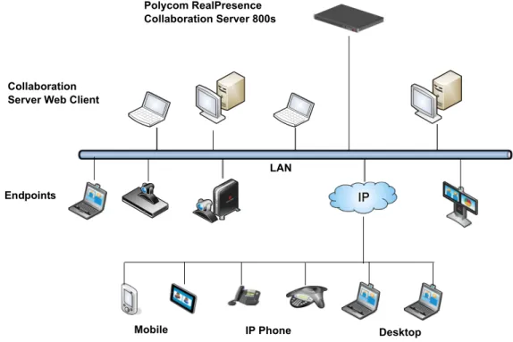
The following diagram describes the multipoint video conferencing configuration with the RealPresence Collaboration Server 800s as a standalone MCU system.
Figure 1-1 Multipoint Video Conferencing using a RealPresence Collaboration Server 800s Collaboration
Server Web Client
Desktop IP Phone Endpoints Polycom RealPresence Collaboration Server 800s LAN Mobile
The Polycom RealPresence Collaboration Server 800s unit can be controlled via the LAN, by the Collaboration Server Web Client application, using Internet Explorer installed on the user’s workstation or the RMX Manager application. The RMX Manager can control several MCU units. For more information about the RMX Manager, see "RMX Manager Application” on page19-1.
MCU management and IP conferencing are performed via two different LAN ports. The networks can be separated in Maximum Security Environments.Management and IP Service can be combined in one LAN port or separate to different ports.
RealPresence Collaboration Server Main Features
Conferencing Modes
The MCU system offers the following Conferencing Modes: • Media Relay - SVC Conferencing
• Mixed CP and SVC Conferencing
• CP Transcoding - AVC-based Conferencing
A transcoded CP (Continuous Presence) conference is also described as an AVC (Advanced Video Coding) conference. It supports the standard video protocols. In this mode, video is received from all the endpoints using different line rates, different protocols (SIP, H.323) and video parameters:
• Video protocols: H.263, H.264 Base and High profile and RTV • Video Resolutions: from QCIF, CIF and up to 720p
• Frame rates up to 3060fps
All endpoints that do not support the H.264 SVC protocol such as H.263, and H.264, or RTV, are considered AVC endpoints.
The MCU process the received video, transcodes it and send the resulting video streams to the endpoints. The video processing that is required differs according to the video session set for the conference, with all the processing performed by the MCU. For more details, see Polycom® RealPresence Collaboration Server 800s Administrator’s Guide, "AVC Conferencing - Video Session Types” on page2-4.
Media Relay - SVC Conferencing
Media Relay SVC Conferencing is based on the Scalable Video Coding (SVC) video protocol and SAC Polycom's proprietary Scalable Audio Coding protocol. It offers high resolution video conferencing with low end-to-end latency, improved Error Resiliency and higher system capacities.
The Polycom multipoint media server, serves as an integrated media relay engine that provides media streams for displaying conferences at low latency video experience in video conferences. For more details, see Polycom® RealPresence Collaboration Server 800s
Administrator’s Guide, "SVC-based Conferencing” on page2-9. Mixed CP and SVC Conferencing
R R
In the same way, the MCU processes the video streams received from the SVC participants, converts them into AVC video and then transcodes all the video streams to compose the video layout that is sent to the AVC endpoints.
AVC-based Video Session Types
All endpoints have AVC capabilities and can connect to AVC conferences running on the MCU. AVC-based endpoints can connect using different signaling protocols and different video protocols.
Dynamic Continuous Presence
The dynamic Continuous Presence (CP) capability of the Collaboration Server system enables viewing flexibility by offering multiple viewing options and window layouts for video conferencing. By default every conference, Entry Queue and Meeting Room has the ability to declare the maximum CP resolution as defined for the system. This includes conferences launched by the Collaboration Server Web Client and conferences started via the API.
For more details, see Polycom® RealPresence Collaboration Server 800s Administrator’s Guide, "Continuous Presence (CP) Conferencing” on page2-4.
Video Layouts in CP
A selection of layouts are available to accommodate different numbers of participants and conference settings.
Multiple Switching Modes
If the number of participants is higher than the number of video windows in the selected layout, switching between video participants can be performed in one of these modes: • Voice activation (default mode)
• The Collaboration Server user forces participants to selected video window
• Lecture Mode - The lecturer is viewed in full screen by all conference participants, while the audience is “time-switched” in the speaker’s view
• Presentation Mode - When the speaker’s presentation extends beyond a predefined time, he/she becomes the current lecturer and the conference switches to Lecture Mode
Operator Conference
In Continuous Presence conferencing, a special conference that enables the MCU user, acting as an operator, to assist participants without disturbing ongoing conferences and without being heard by other conference participants. The operator can move a participant from an Entry Queue or ongoing conference to a private, one-on-one conversation in the Operator conference. For more details, see Polycom® RealPresence Collaboration Server 800s Administrator’s Guide, "Operator Conferences” on page10-1.
AVC-based Video Resolutions
Resolution Configuration for AVC-based CP Conferences
The Resolution Configuration dialog box enables the Collaboration Server administrators to modify the video resolution decision matrix, effectively creating their own decision matrix. The minimum threshold line rates at which endpoints are connected at the various video resolutions can be optimized by adjusting the resolution sliders.
For more information see the Polycom® RealPresence Collaboration Server 800s Administrator’s Guide, "Video Resolutions in AVC-based CP Conferencing” on page4-1.
SVC-based Conferencing
In the Scalable Video Codec (SVC)-based conference, each SVC-enabled endpoint transmits multiple bit streams, to the Polycom® RealPresence® Collaboration Server. Simulcasting enables each endpoint to transmit at different resolutions and frame rates such as 720p at 30fps, 15fps, and 7.5fps, 360p at 15fps and 7.5fps, and 180p at 7.5fps.
Using the SVC video protocol, SVC conferences relays the received video streams to the SVC-enabled endpoints at different resolutions, frame rates and line rates according to the endpoint’s display capabilities and layout configurations without sending the entire video layout to the endpoints.
For more details, see Polycom® RealPresence Collaboration Server 800s Administrator’s Guide, "SVC-based Conferencing” on page2-9.
H.239
The H.239 protocol allows compliant endpoints to share content. By default, all Conferences, Entry Queues, and Meeting Rooms launched on the Collaboration Server have H.239
capability.
For more details, see Polycom® RealPresence Collaboration Server 800s Administrator’s Guide, "Content Sharing” on page3-1.
IVR-Enabled Conferencing
Interactive Voice Response (IVR) is a software module that automates the connection process and lets participants perform various operations during ongoing conferences. The participants use their endpoints’ keypads, remote controls and touch control devices to interact with the conference’s menu-driven scripts using DTMF codes.
Operations that can be performed by participants or chairpersons during a conference include:
• Mute or unmute the participant’s audio channel. • Play the Help menu.
• Mute or unmute undefined dial-in participants upon their connection to the conference. • Secure and unsecure a conference.
• Request individual and conference assistance (CP conferences). • Manually terminate the conference.
For more details, see Polycom® RealPresence Collaboration Server 800s Administrator’s Guide, "IVR Services” on page17-1.
This service can also be used (if required) to verify the participant’s right to start an Ad Hoc conference or to join an ongoing conference.
For more details, see Polycom® RealPresence Collaboration Server 800s Administrator’s Guide, "Entry Queues” on page7-1.
Conferencing Capabilities and Options
On Demand Conferencing
The following options are available to set up conferences: • New Conference – set up once, use once.
The conference is deleted from the MCU after it ends. • Meeting Rooms – set up once, use many times.
Meeting Rooms are saved in memory (using no resources) and can be activated as many times as needed.
• Ad Hoc Entry Queue(CP and Mixed CP and SVC Conferencing) – no setup, a new
conference can be created when an AVC participant dials in and enters a conference ID that is not being used by an existing conference or Meeting Room.
Permanent Conference
A Permanent Conference is an ongoing conference with no predetermined End Time, continuing until it is terminated by an administrator, operator or chairperson. For more details, see Polycom® RealPresence Collaboration Server 800s Administrator’s Guide, "Permanent Conference” on page3-50.
Scheduled Conferencing / Reservations
Reservations provide calendar-based scheduling of single or recurring conferences. These conferences can be launched immediately or become ongoing, at a specified time on a specified date. For more details, see Polycom® RealPresence Collaboration Server 800s Administrator’s Guide, "Reservations” on page9-1.
Polycom Conferencing for Microsoft Outlook® (AVC-based
Conferencing)
Polycom Conferencing for Microsoft Outlook is implemented by installing the Polycom Conferencing Add-in for Microsoft Outlook on Microsoft Outlook -mail clients. It enables meetings to be scheduled with video endpoints from within Outlook. The add-in also adds a Polycom Conference button in the Meeting tab of the Microsoft Outlook e-mail client ribbon. For more details, see Polycom® RealPresence Collaboration Server 800s Administrator’s Guide, "Polycom Conferencing for Microsoft Outlook®” on page12-1.
Connection Methods
All endpoints that do not support the H.264 SVC protocol such as H.263, H.264, or RTV, are considered AVC endpoints.
AVC-based Connections
In AVC-based connection, H.323 and SIP communication protocols issupported for connection to the conference.
Endpoints can connect using the following Video Protocols: H.263, H.264 Base and High Profile and RTV.
• Dial-out: automatically, to pre-defined participants (line rate detection is automatic) • Dial-in:
— for participants defined in advance
— for undefined participants connecting directly to a conference
— for undefined participants via a single dial Entry Queue SVC-based Connections
In SVC-based connections, IPv4 SIP communication protocol is supported for connection to the conference. Endpoints can connect using the SVC Video Protocol.
• Dial-out: not supported for SVC participants in SVC Only or mixed CP and SVC conferences
• Dial-in:
— for participants defined in advance
— for undefined participants connecting directly to a conference (SIP)
Cascading Conferences (AVC-based Conferencing)
Cascading enables administrators to connect one conference directly to one or several conferences usually running on different MCUs, depending on the topology, creating one large conference. Supported topologies are:
• Basic Cascading of two MCUs. • Star Topology.
For more details, see Polycom® RealPresence Collaboration Server 800s Administrator’s Guide, "Cascading Conferences” on page5-1.
Security
• In CP conferences Media Encryption is available at conference and participant levels, based on AES 128 Media Encryption and DH 1024 Key Exchange standards.
• Secured Communication Mode (SSL/TLS).
• Secured conferences via DTMF codes and limited monitoring of secured conferences. • Auditor to analyze configuration changes and unusual or malicious activities in the
Collaboration Server.
• Network security can be enhanced by separation of the Signaling and Management Networks.
• The following additional Security features can be implemented:
— Password management:
• Strong Passwords and password re-use / history rules,
• password aging rules, password change frequency and forcing password change
• Conference and Chairman Passwords • Locking out Users
• Displaying the User Login record
— Controlling the User Sessions includes:
• Limiting the maximum number of concurrent user sessions • Connection Timeout
• User session timeout
• Limiting the maximum number of users that can connect to the system • Multiple Network Services
LAN Redundancy
Enables the redundant LAN port connection to automatically replace the failed LAN port by using another physical connection and NIC (Network Interface Card) should a LAN port fail. For more details, see Polycom® RealPresence Collaboration Server 800s Administrator’s Guide, "LAN Redundancy” on page16-35.
Conference Management and Monitoring Features
The Collaboration Server Web Client and RMX Manager application provide capabilities for management and monitoring of participants and conferences, including the following:
CP AVC-based and SVC-based Conferencing
• Active display of all conferences and participants
• Real-time monitoring of each participant’s connection status and properties. • Automatic termination of idle (no participants) conferences.
• Automatic extension of conference Duration.
• Control of listening and broadcasting audio volume for individual participants. • Easily accessed Call Detail Records (CDR) for administrator.
• Active display of all system resources.
• Hot Backup implements a high availability and rapid recovery solution.
CP AVC-based Conferencing
• Lecture Mode or Presentation Mode in Continuous Presence conferences. • Far End Camera Control (FECC/LSD) in video conferences.
• Conference control via DTMF codes from participant’s endpoint or telephone. • Media Encryption.
• Option to limit the properties display of conference participants in secured conferences. • Multiple drag & drop of participants.
• Auto Redial when Endpoint Drops instructs the Collaboration Server to automatically redial IP and SIP participants that have been abnormally disconnected from the conference.
• Operator Assistance & Participant Move for conferences in CP mode.
Workstation Requirements
The Collaboration Server Web Client and RMX Manager applications can be installed in an environment that meets the following requirements:
• Minimum Hardware – Intel® Pentium® III, 1 GHz or higher,1024 MB RAM, 500 MB free disk space.
• Workstation Operating System – Microsoft® Windows® XP, Vista®, Windows® 7. • Network Card – 10/100/1000 Mbps.
• Web Browser - Microsoft® Internet Explorer® Version 7, 8 and 9.
• Collaboration Server Web Client and RMX Manager are optimized for display at a resolution of 1280 x 800 pixels and a magnification of 100%.
Microsoft Windows 7™ Security Settings
If Windows 7 is installed on the workstation, Protected Mode must be disabled before downloading the software to the workstation.
To disable Protected Mode:
1 In the Internet Options dialog box, click the Security tab. .Net Framework 2.0 is required and installed automatically.
If ActiveX installation is blocked please see the Polycom® RealPresence Collaboration Server 800s Administrator’s Guide, "ActiveX Bypass” on page20-57.
Collaboration Server Web Client does not support larger Windows text or font sizes. It is
recommended to set the text size to 100% (default) or Normal in the Display settings in Windows Control Panel on all workstations. Otherwise, some dialog boxes might not appear properly aligned. To change the text size, select Control Panel>Display. For Windows XP, click the Appearance tab, select Normal for the Font size and click OK. For Windows 7, click the Smaller - 100% option and click OK.
When installing the Collaboration Server Web Client, Windows Explorer >Internet Options> Security Settings must be set to Medium or less.
It is not recommended to run Collaboration Server Web Client and Polycom CMAD applications simultaneously on the same workstation.
2 Clear the Enable Protected Mode check box for each of the following tabs:
— Internet
— Local intranet
— Trusted sites
3 After successful connection to Collaboration Server, the Enable Protected Mode check boxes can be selected to enable Protected Mode for the following tabs:
— Internet
— Local intranet
Internet Explorer 8 Configuration
When using Internet Explorer 8 to run the RP Collaboration Server Web Client or RMX Manager applications, it is important to configure the browser according to the following procedure.
3 Open Internet Explorer but do not connect to the MCU.
4 In the Internet Explorer menu bar select Tools >> Internet Options. The Internet Options dialog box is displayed with General tab open.
5 In the Browsinghistory section, click the Delete button. The Delete Browsing History dialog box is displayed.
6 Select the Temporary Internet files and Cookies check boxes. 7 Click the Delete button.
8 The Delete Browsing History dialog box closes and the files are deleted. 9 In the Internet Options dialog box, click the Settings button.
The Temporary Internet Files and History Settings dialog box is displayed.
10 Click the View objects button.
The Downloaded Program Files folder containing the installed Program Files is displayed.
11 Select the EMAClassLoader.dll file and press the Delete key on the workstation or right-click the EMA.ClassLoader.dll file and then click Delete.
12 Close the Downloaded Program Files folder and the Temporary Internet Files and History Settings dialog box.
13 In the Internet Options dialog box, click the OK button to save the changes and close the dialog box.
2
First Time Installation and
Configuration
First Time Installation and Configuration of the RealPresence Collaboration Server 800s Virtual Edition consists of the following procedures:
1 Preparations:
— Gather Network Equipment and Address Information - get the information needed for integrating the RealPresence Collaboration Server 800s into the local network.
— Unpack the Polycom® RealPresence Collaboration Server 800s.
— Modify the Management Network parameters on the USB memory stick. 2 Hardware Installation and Setup
— Mount the Collaboration Server in a rack.
— Connect the necessary cables. 3 First Entry Power-up and Configuration
— Power up the RealPresence Collaboration Server 800s.
— Register the RealPresence Collaboration Server 800s.
— Connect to the RealPresence Collaboration Server 800s.
— Configure the Default IP Network Service.
Preparations
Gather Network Equipment and Address Information
IP Services
The IP addresses and network parameters which enable communication between the Polycom® RealPresence Collaboration Server 800s, its management application and the conferencing devices are organized in two IP services:
• Management Network (Control Unit)
• Default IP Service (Conferencing Service which includes the signaling and media) During the First Entry Configuration, the parameters of these two network services are modified to comply with your local network settings.
Hardware Installation and Setup First Entry Power-up and Configuration Preparations Preparations Hardware Installation and Setup First Entry Power-up and Configuration
Management Network
The Management Network enables communication between the RealPresence Collaboration Server 800s and the Collaboration ServerWeb Client and is used to manage the MCU. The Collaboration Server is shipped with default IP addresses as listed in Table 2-1. Management Network Definition
The configuration of the Management Network can be done by two methods:
• USB Memory Stick (recommended method) – The system is shipped with a USB Memory Stick containing the default IP addresses for the Control Unit.
These IP addresses are first modified in the administrator’s PC and then uploaded to the RealPresence Collaboration Server 800s.
• Direct connection – Creating a private network between the RealPresence
Collaboration Server 800s and the computer and modifying the management network parameters using Fast Configuration Wizard in the Collaboration Server Web Client. For more information, see the Polycom® RealPresence Collaboration Server 800s Administrator’s Guide, "Configuring Direct Connections to the Collaboration Server” on pageF-1.
DHCP is not supported in the Management Network.
Default IP Service (Conferencing Service)
The Default IP Service (Conferencing Service) is used to configure and manage
communications between the RealPresence Collaboration Server 800s and conferencing devices.
IP Network Services Required Information
When installing the RealPresence Collaboration Server 800s, these default IP addresses must be modified to your local network settings. Therefore it is important that before powering up the RealPresence Collaboration Server 800s for the first time, that you obtain the information needed to complete the Local Network Settings section of the table from your network administrator.
For each MCU, an IP address must be allocated in the local network for the: • Control Unit
• Signaling Host Example:
The network administrator should allocate TwoIP addresses in the local network for a RealPresence Collaboration Server 800s: Control Unit and Signaling Host. Since the signaling and media are transferred on the same network, the same IP address is allocated to both.
Conferencing (Media and signaling) and Management networks can be logically separated on the Collaboration Server to provide enhanced security. Up to three media and signaling networks can be defined. For more information see “Multiple Networks” in the Polycom® RealPresence Collaboration Server 800s Administrator’s Guide.
Installing the RealPresence Collaboration Server 800s
The installation of the RealPresence Collaboration Server 800s consists of the following procedures:• Unpacking the RealPresence Collaboration Server 800s • Hardware Installation and Rack Mounting
• Connecting the Cables to the MCU
• Modifying the Factory Default Management Network Settings on the USB Memory Stick
Unpacking the RealPresence Collaboration Server 800s
The RealPresence Collaboration Server 800s system uses a Polycom-branded Dell server. To unpack and install the hardware:
1 Examine the shipping container for damage. If you find damage, file a claim with the delivery carrier. Polycom® is not responsible for damage sustained during shipment of this product.
2 Open and review the container packing slips.
3 Open the container and examine the contents. The system server package includes these items:
— The Polycom RealPresence Collaboration Server 800s system.
— The Polycom® RealPresence Collaboration Server 800s Virtual Edition Quick Start Guide
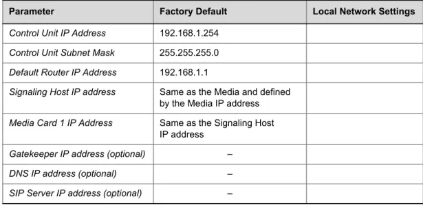
— The server Product Information Guide. Table 2-1 Network Equipment and Address Information
Parameter Factory Default Local Network Settings
Control Unit IP Address 192.168.1.254
Control Unit Subnet Mask 255.255.255.0
Default Router IP Address 192.168.1.1
Signaling Host IP address Same as the Media and defined by the Media IP address
Media Card 1 IP Address Same as the Signaling Host IP address
Gatekeeper IP address (optional) –
DNS IP address (optional) –
— Two LAN cables
— Rack-mount kit
— Bezel assembly and key
— RealPresence Collaboration Server 800s recovery DVD (included for recovery purposes; this software is already installed on the server)
— A USB memory stick with hardware diagnostic utilities (to be used only under the direction of Polycom® Global Services)
— A USB memory stick which contains the LAN Configuration Utility, support utilities and documentation.
4 Examine the contents for damage. Again, if you find damage, file a claim with the delivery carrier.
5 Unpack your system and identify each item. Keep all shipping materials in case you need them later.
Hardware Installation and Rack Mounting
1 Read the “Safety Instructions” in the Rack Installation Guide and then use the brackets provided to install the system in the rack.
2 Assemble the rails and install the system in the rack following the safety instructions and the rack installation instructions provided with your system.
3 Connect the system’s power cable(s) to the system.
4 Plug the other end of the cable into a grounded electrical outlet or separate power source such as an uninterrupted power supply (UPS) or a power distribution unit (PDU).
Connecting the Cables to the MCU
>> Connect the RealPresence Collaboration Server 800s system server to the network:
a Connect a LAN cable between the leftmost Ethernet port and the enterprise network. This is the eth0 Management Network interface, which must be used for this purpose.
b Connect the second LAN cable between the second Ethernet port to the network to be used for signaling and media traffic. This is the eth1 network interface, which must be used for this purpose.
When LAN redundancy is enabled, LAN 1 is used for both management, media and signaling network connection.Connect the media and signaling cable to LAN 2 port. By default this port is used for signaling, but when LAN redundancy is enabled, LAN 2 is the backup of LAN 1 port.
Modifying the Factory Default Management Network Settings on the USB
Memory Stick
The USB memory stick contains a text file, lan.cfg, which holds the factory default IP address parameters. These parameters must be modified to your local network settings using the LAN Configuration Utility, also available on the USB memory stick.
To modify the USB memory stick settings:
1 Take the USB memory stick from the Installation Accessories kit and insertit into the PC workstation.
The Polycom RealPresence Collaboration Server Documentation Library & Initial Setup Tools window opens.
— Select Open Folder to view files using Windows Explorer. LAN port for
Management (eth0)
LAN port for Signaling and Media (eth1)
2 Double-click the index.hta file.
The LanguageMenu opens, offering a choice of several languages.
3 Click the documentation language of your choice.
An End-User Licence Agreement for Polycom Software is displayed. 4 Read the agreement and click the Accept Agreement button.
6 In the Initial Setup Utility screen, click the LAN Configuration Utility link.
The LAN Configuration Utility dialog box opens.
7 Modify the following parameters in the utility’s dialog box using the information supplied by your network administrator.
— Control Unit IP Address (the Management IP address for the MCU)
— Subnet Mask
— Default Router IP Address 8 Click OK.
9 Remove the USB memory stick from the PC workstation.
First Entry Power-up and Configuration
There are four procedures necessary for setup of the new RealPresence Collaboration Server. It is important that they are performed in the following sequence:
1 First-time Power-up 2 Product Registration. 3 Connection to MCU.
4 Modifying the Default IP Service Settings (Fast Configuration Wizard).
Procedure 1: First-time Power-up
To power-up for the first time using the USB memory stick:
1 Insert the USB memory stick containing the modified IP addresses in USB port on the RealPresence Collaboration Server 800s front or back panel.
2 Press the power button on the system. The power indicators should light.
System power-up sequence may take approximately 5 minutes.
During this time, the parameters in the lan.cfg file are uploaded from the USB memory stick to the MCU’s memory and applied during the power-up sequence.
Wait for the upload process to complete. Do not remove the USB memory stick from the RealPresence Collaboration Server 800s until the connection with the MCU is
established and the Login screen of the Collaboration Server Web Client is displayed. For more details, see "Procedure 3: Connection to MCU” on page2-9.
Preparations Hardware Installation and Setup First Entry Power-up and Configuration
During first-time power-up, the Product Activation dialog box is displayed in the Collaboration Server Web Client, requesting you to enter an Activation Key.
Obtaining the Activation Key
1 Access the Service & Support page of thePolycomwebsite at:
http://support.polycom.com
2 Log in with your Email Address and Password or register as a new user. 3 Select Product Registration.
4 Follow the on-screen instructions for Product Registration and Product Activation. (The MCU’s serial number/service tag (tagged as ST) on the product sticker on the back of the unit.).
5 When the Product Activation Key is displayed, write it down or copy itfor laterpasting into the Activation Key field of the Product Activation dialog box.
Procedure 3: Connection to MCU
1 Start the Collaboration Server Web Client application on the workstation.
a In the browser’s address line, enter the IP address of the Control Unit in the format: http://<Control Unit IP Address>, as defined in the USB memory stick. b Click Enter.
The Collaboration Server Web Client Login screen is displayed.
Register all Polycom Software Licences that you have purchased when obtaining the Activation Key. For example, Encryption and Multiple Networks each have different Polycom Software Licenses.
If Windows7™ is installed on the workstation, Protected Mode must be disabled before connecting to the MCU. For more information, see "Microsoft Windows 7™ Security Settings” on page1-10.
Once the connection with the MCU is established, you can remove the USB memory stick from the system.
If the error “Browser environment error. Please close all the browser sessions” appears, close all the browser sessions, and reconnect to the MCU. If the error message appears again, either run the automatic troubleshooter utility or manually perform the suggested troubleshooting procedures. For
2 In the Collaboration Server Web Client Login screen, enter the default Username (POLYCOM) and Password (POLYCOM) and click Login.
The Collaboration Server Web Client opens and the Product Activation dialog box appears with the serial number filled in:
3 Select the “I accept the license agreement” check box to enable Online Registration of your product.
4 In the Activation Key field, enter or paste the Product Activation Key obtained earlier. If you did not register your product earlier in the process and you do not have an Activation Key, click the Polycom Resource Center button to access the Service & Support page of the Polycom Support website.
5 Click OK.
A message indicating that the Product Activation Key was loaded successfully appears. If the Product Activation Key fails to load, please contact your vendor.
Procedure 4: Modifying the Default IP Service Settings
The Fast Configuration Wizard is automatically started when no Default IP Network Service is defined and it assists you in configuring the Default IP Network Service. This happens during First Time Power-up,before the service has been defined or if the Signaling Service has been deleted, followed by an Collaboration Server restart.
The IP Management Service tab in the Fast Configuration Wizard is enabled only if the factory default Management IP addresses were not modified.
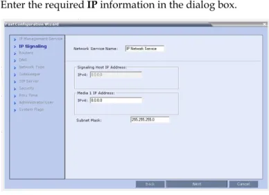
Fast Configuration Wizard
1 Enter the required IP information in the dialog box.
Table 2-2 Fast Configuration Wizard – IP Signaling
Field Description
Network Service Name
The name Default IP Service is assigned to the IP Network Service by the Fast Configuration Wizard. This name can be changed.
Note: This field is displayed in all IP Signaling dialog boxes and can contain character sets that use Unicode encoding.
Signaling Host IP Address
In the RealPresence Collaboration Server 800s, this field is disabled as only one IP address is used for the Signaling Host and the Media Card and it is defined by the Media Card IP address.
Media Card 1 IP Addresses
In the RealPresence Collaboration Server 800s, one IP address is used for the signaling and media.
Enter the address to be used by IP endpoints when dialing into the MCU.
Dial out calls from the Collaboration Server are initiated from this address.
This address is used to register the Collaboration Server with a Gatekeeper or a SIP Proxy server.
Subnet Mask Enter the subnet mask of the MCU. Default value: 255.255.255.0.
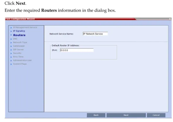
2 Click Next.
3 Enter the required Routers information in the dialog box.
4 Click Next.
• To set the Collaboration Server to Secured Communication, first complete the Fast Configuration Wizard and reset the Collaboration Server. After Login, install the Certificate and then enable
Secured Communication Mode.
• The IP Network Service configured using the Fast Configuration Wizard will be saved only if Media cards are installed in the Collaboration Server.
Table 2-3 Fast Configuration Wizard – Routers
Field Description
Default Router IP Address
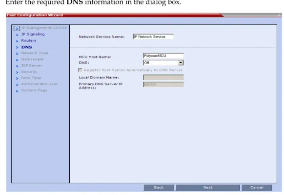
5 Enter the required DNS information in the dialog box.
6 Click Next.
Table 2-4 Fast Configuration Wizard – DNS
Field Description
MCU Host Name Enter the name of the MCU on the network. Default name is Polycom MCU.
DNS Select:
• Off – if DNS servers are not used in the network.
• Specify – to enter the IP addresses of the DNS servers.
Note: The IP address fields are enabled only if Specify is selected.
Register Host Names Automatically to DNS Server
Select this option to automatically register the MCU Signaling Host with the DNS server.
Local Domain Name Enter the name of the domain where the MCU is installed.
Primary DNS Server IP Address
7 Select the IP Network Type: H.323, SIP or H.323 & SIP.
8 Click Next.
9 If you selected SIP only, go to Step 13.
10 Enter the required Gatekeeper information in the dialog box.
The Collaboration Server supports SVC-based conferencing, which is based on the SIP protocol. If SVC-based conferencing is required in your organization, select SIP as one of your Network Type options.
11 Click Next.
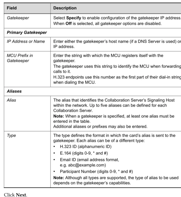
12 If you selected H.323, click Next and go to Step 14. Table 2-5 Fast Configuration Wizard – Gatekeeper
Field Description
Gatekeeper Select Specify to enable configuration of the gatekeeper IP address. When Off is selected, all gatekeeper options are disabled.
Primary Gatekeeper
IP Address or Name Enter either the gatekeeper’s host name (if a DNS Server is used) or IP address.
MCU Prefix in Gatekeeper
Enter the string with which the MCU registers itself with the gatekeeper.
The gatekeeper uses this string to identify the MCU when forwarding calls to it.
H.323 endpoints use this number as the first part of their dial-in string when dialing the MCU.
Aliases
Alias The alias that identifies the Collaboration Server’s Signaling Host within the network. Up to five aliases can be defined for each Collaboration Server.
Note: When a gatekeeper is specified, at least one alias must be entered in the table.
Additional aliases or prefixes may also be entered.
Type The type defines the format in which the card’s alias is sent to the gatekeeper. Each alias can be of a different type:
• H.323 ID (alphanumeric ID)
• E.164 (digits 0-9, * and #)
• Email ID (email address format, e.g. [email protected])
• Participant Number (digits 0-9, * and #)
Note: Although all types are supported, the type of alias to be used depends on the gatekeeper’s capabilities.
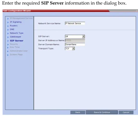
13 Enter the required SIPServer information in the dialog box.
Table 2-6 Fast Configuration Wizard – SIP Server
Field Description
SIP Server Select:
• Specify – to manually configure SIP servers.
• Off – if SIP servers are not present in the network.
SIP Server IP Address
Enter either the IP address of the preferred SIP server or its host name (if a DNS server is used).
Transport Type Select the transport type and protocol that is used for signaling between the MCU and the SIP Server or the endpoints according to the protocol supported by the SIP Server:
• UDP – Select this option to use UDP for signaling.
• TCP – Select this option to use TCP for signaling.
• TLS – The Signaling Host listens on secured port 5061 only and all outgoing connections are established on secured connections. Calls from SIP clients or servers to non secured ports are rejected.
The following protocols are supported:
• TLS 1.0
• SSL 2.0
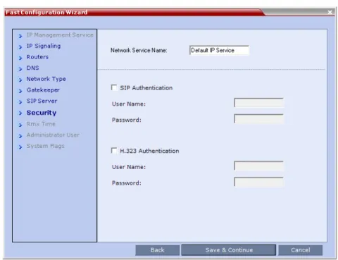
14 Enter the required Security information in the dialog box.
Table 2-7 Default IP Network Service – Security
Field Description
SIP Authentication Click this check box to enable SIP proxy authentication.
Select this check box only if the authentication is enabled on the SIP proxy, to enable the Collaboration Server to register with the SIP proxy. If the authentication is enabled on the SIP proxy and disabled on the Collaboration Server, calls will fail to connect to the
conferences.
Leave this check box cleared if the authentication option is disabled on the SIP proxy.
User Name Enter the user name the Collaboration Server will use to authenticate itself with the SIP proxy. This name must be defined in the
gatekeeper. These fields can
contain up to 20 ASCII characters.
Password Enter the password the Collaboration Server will use to authenticate itself with the
gatekeeper. This password must be defined in the SIP proxy.
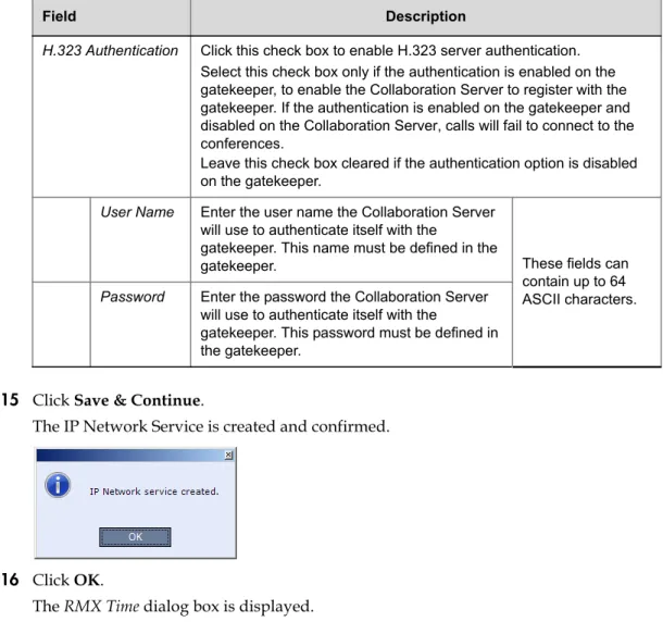
15 Click Save & Continue.
The IP Network Service is created and confirmed.
16 Click OK.
The RMX Time dialog box is displayed.
17 Set the RMX Time using one of the three available options: setting the RMX Time manually, clicking the Retrieve Client Time button, or using the NTP Servers options.
H.323 Authentication Click this check box to enable H.323 server authentication. Select this check box only if the authentication is enabled on the gatekeeper, to enable the Collaboration Server to register with the gatekeeper. If the authentication is enabled on the gatekeeper and disabled on the Collaboration Server, calls will fail to connect to the conferences.
Leave this check box cleared if the authentication option is disabled on the gatekeeper.
User Name Enter the user name the Collaboration Server will use to authenticate itself with the
gatekeeper. This name must be defined in the
gatekeeper. These fields can
contain up to 64 ASCII characters.
Password Enter the password the Collaboration Server will use to authenticate itself with the
gatekeeper. This password must be defined in the gatekeeper.
Table 2-7 Default IP Network Service – Security (Continued)
Field Description
Table 2-8 Fast Configuration Wizard - Collaboration Server Time
Field Description
GMT Date The date at Greenwich, UK.
Local Time The MCU’s local time settings, are calculated from the GMT Time
and the GMT Offset.
GMT Time Displays the MCU’s current GMT Time settings.
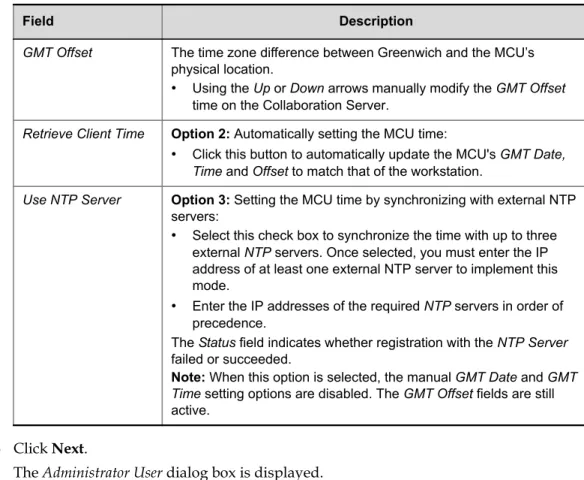
18 Click Next.
The Administrator User dialog box is displayed.
GMT Offset The time zone difference between Greenwich and the MCU’s physical location.
• Using the Up or Down arrows manually modify the GMT Offset
time on the Collaboration Server.
Retrieve Client Time Option 2: Automatically setting the MCU time:
• Click this button to automatically update the MCU's GMT Date, Time and Offset to match that of the workstation.
Use NTP Server Option 3: Setting the MCU time by synchronizing with external NTP servers:
• Select this check box to synchronize the time with up to three external NTP servers. Once selected, you must enter the IP address of at least one external NTP server to implement this mode.
• Enter the IP addresses of the required NTP servers in order of precedence.
The Status field indicates whether registration with the NTP Server
failed or succeeded.
Note: When this option is selected, the manual GMT Date and GMT Time setting options are disabled. The GMT Offset fields are still active.
Table 2-8 Fast Configuration Wizard - Collaboration Server Time (Continued)
19 Enter the required Administrator User information:
20 Click Next.
The System Flags dialog box is displayed.
21 Enter the required System Flags information in the dialog box. Table 2-9 Fast Configuration Wizard - Administrator User
Field Description
New User Name Enter the new user name of the new administrator user.
New Password Enter the password for the new administrator user.
Confirm Password Enter the same password again to confirm its accuracy.
Table 2-10 Fast Configuration Wizard – System Flags
Field Description / Default
Conference ID Length (MCU)
The number of digits of the Conference ID to be assigned by the MCU.
Range: 2-16 (Default: 5)
Note: Selecting 2 digits limits the number of simultaneous ongoing conferences to 99.
Minimum Conference ID Length (User)
The minimum number of digits that the user must enter when manually assigning a numeric ID to a conference. Range: 2-16 (Default: 4)
Maximum Conference ID Length (User)
The maximum number of digits that the user can enter when manually assigning a Numeric ID to a conference.
These flags can be modified later, if required, by selecting the System Configuration option from the Setup menu. For more information, see the Polycom® RealPresence Collaboration Server 800s Administrator’s Guide, "Modifying System Flags” on page21-1. 22 Click Save & Close.
The system confirms successful configuration. 23 In the Success Message box, click OK.
24 In the Reset Confirmation dialog box, click Yes.
25 In the Please wait for system reset message box, click OK.
26 Refresh the browser periodically until the Login screen is displayed.
27 When the Login screen is displayed, enter your Username and Password and click Login.
Selecting the Collaboration Server Web Client Languages
By default, the Collaboration Server Web Client interface is displayed only in English. However, the system administrator can choose the languages available for selection on the Login screen. These languages are represented by flags.
To choose the languages for selection in the Login screen:
1 On the Collaboration Server menu, click Setup > Customized Display Settings > Multilingual Setting.
Terminate Conference when Chairperson Exits
When Yes is selected (default), the conference ends when the chairperson exits even if there are other participants connected. When No is selected, the conference automatically ends at the predefined end time, or when all the participants have disconnected from the conference.
Auto Extend Conferences
When Yes is selected (default), allows conferences running on the Collaboration Server to be automatically extended as long as there are participants connected and there are available resources. The maximum extension time allowed by the MCU is 30 minutes.
Table 2-10 Fast Configuration Wizard – System Flags (Continued)
Field Description / Default
System restart may take up to five minutes.
The Fast Configuration Wizard configures the Default IP Network Service with common parameters. Specific or additional settings (e.g. for ICE, or Secured Mode) should be performed once the initial configuration is complete. For detailed description of the IP Network Services, see the Polycom® RealPresence Collaboration Server 800s Administrator’s Guide, Network Services.
2 Click the check boxes of the languages to appear in the Login screen of the Collaboration Server Web Client. For more information see the Polycom® RealPresence Collaboration Server 800s Administrator’s Guide, "Multilingual Setting” on page20-36.
If the selected language is not supported by the browser or the workstation’s Operating System, the Collaboration Server Web Client is displayed in English.
3 Click OK.
4 Log out and reconnect to the Collaboration Server.
The Login screen will display the flags of the selected languages.
RealPresence Collaboration Server 800s Default
Conferencing Settings
The Collaboration Server is shipped with default pre-configured conferencing entities set to CP (AVC) Conferencing Mode, which allow the MCU users and participants to start CP AVC ongoing conferences without further configuration.
The default conferencing entities are:
Table 2-11 Default AVC-based Conferencing Entities
Entity Description
Meeting Rooms Conferences saved on the MCU without using resources. They are activated when the first participant dials in.
There are four Meeting Rooms ready for use:
Name ID
Maple_Room 1001 Oak_Room 1002 Juniper_Room 1003 Fig_Room 1004
Each Meeting Room uses the default Conference Profile called
Factory_Mix_SVC_CP_Video_Profile set to Mixed SVC and CPCP (AVC) Only Conferencing Mode, running at 1920Kbps and has a default duration of one hour.
Conference Profile Name: Factory_Mix_SVC_CP_Video_Profile
A Mixed CP and SVC Conference Profile is assigned to a Meeting Room to define its Conferencing Mode, conferencing parameters, such as line rate and video resolution.
Factory_Mix_SVC_CP_Video_Profile is set to a line rate of 1920Kbps,
Auto Layout and contains video parameters that can be used for connection to conference by both AVC and SVC enabled endpoints. The Profile uses an IVR Service called Conference IVRService.In addition to the default Conference Profile, the system is shipped with the following default Conference Profiles:
SVC-Conference IVR Service Name: Conference IVR Service
The Conference IVR Service includes an optional video slide and all the voice messages played during the participant’s connection process and during the conference.
The Conference IVR Service contains a set of voice prompts in English and an optional video slide.
It automates the participant’s connection to a conference.
Entry Queue
(AVC endpoints)
Name ID
DefaultEQ 1000
Using an Entry Queue enables one dial-in number to be used for all AVC-based connections. In the Entry Queue, AVC participants are prompted for information to enable routing to their destination conferences.
A default Entry Queue called DefaultEQ is provided.
The default Entry Queue is also set to Ad Hoc conferencing which allows participants to start new conferences without prior definition by entering a Conference or Meeting Room ID that is not used by any ongoing conference currently running on the MCU. It uses an Entry Queue IVR Service called Entry Queue IVR Service.
The default Welcome Slide displayed at the participants endpoint upon connection to the Entry Queue and lists the default Meeting Rooms. The participant can select one of these Meeting Rooms or enter another ID to start a new conference.
If no Transit Entry Queue is defined, DefaultEQ is the default Transit Entry Queue. For more information see the Polycom® RealPresence Collaboration Server 800s Administrator’s Guide, "Transit Entry Queue” on page7-5.
Entry Queue IVR Service Name: Entry Queue IVR Service
Includes all the voice messages and video slides used to guide AVC participants though their connection process to the MCU and route them to their destination conference.
Entry Queue IVR Service is the default Entry Queue IVR Service provided for the default Entry Queue.
Table 2-11 Default AVC-based Conferencing Entities (Continued)
Customizing the RealPresence Collaboration Server 800s Default
Conferencing Settings
You can customize the conferencing entities to your organization’s requirements:
• To define SVC-based, Mixed CP and SVC or CP Only conferences, a new Conference Profile must be created, setting the appropriate Conferencing Mode, the video
parameters for the conference.
This Profile can be used for defining new ongoing conferences and Meeting Rooms. For more information, see the Polycom® RealPresence Collaboration Server 800s Administrator’s Guide, "Defining New Profiles” on page2-19.
To modify the properties of an existing CP conference Profile,such as the conference line rate, or specific video layout for the conference, create a new Conference Profile. For more information, see the Polycom® RealPresence Collaboration Server 800s Administrator’s Guide, "Defining New Profiles” on page2-19.
To allow AVC participants to connect to a single dial Entry Queueat a line rate other than 384 Kbps (as in the default Entry Queue) or play voice messages in different languages – create a new Entry Queue.
For more information, see the Polycom® RealPresence Collaboration Server 800s Administrator’s Guide,"Defining a New Conference IVR Service” on page17-6.
• You can personalize Meeting Rooms for people in your organization with predefined conference and chairperson passwords (for added security) and allow only authorized people to start on going conferences. For more information, see the Polycom®
RealPresence Collaboration Server 800s Administrator’s Guide, "Meeting Rooms” on page6-1. • The conferencing entities are designed mainly for dial in participants without prior
definition of participants. You can create your own Address Bookcontaining a list of AVC participants to be dialed by the MCU. Once defined, these participants can be added to ongoing conferences saving the need to define them again.
For more information, see the Polycom® RealPresence Collaboration Server 800s Administrator’s Guide, "Address Book” on page8-1.
• You can schedule conferences to start in the future. For more details, see the Polycom® RealPresence Collaboration Server 800s Administrator’s Guide, "Reservations” on page9-1.
3
Basic Operation
The MCU can be controlled using the Collaboration Server Web Client and the RMX Manager application. The most common operations performed via these applications are:
• Starting, monitoring and managing conferences
• Monitoring and managing participants and endpoints as individuals or groups.
— Participant – A person using an endpoint to connect to a conference. When using a Room System, several participants use a single endpoint.
— Endpoint – A hardware device, or set of devices, that can call, and be called by an MCU or another endpoint. For example, an endpoint can be a phone, a camera and microphone connected to a PC or an integrated Room System (conferencing system).
— Group – A group of participants or endpoints with a common name.
Starting the Collaboration Server Web Client
You start the Collaboration Server Web Client by connecting to the MCU system. To connect to the MCU you need to get the following information from your system administrator: • User name
• Password
• MCU Control Unit IP Address
To start the Collaboration Server Web Client:
1 In your browser address line, enter http://<Control Unit IP Address> and press the Enter key.