4 kHz
PO
TS
0.025 0.138
3.75
DS1 US1 DS2 US2 DS3 US3
US0
5.2 8.5 12 23 30 MHz
Splitters and Microfilters—Overview
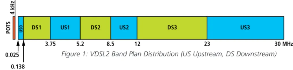
In typical DSL deployments, Voice and DSL services are provide over the same line of twisted-pair copper wires. The copper wires carry signals with frequencies up to 30 MHz (VDSL2), enabling customer data rates of more than 100 MBps. The figure below illustrates an example of a VDSL2 band-plan:
Figure 1: VDSL2 Band Plan Distribution (US Upstream, DS Downstream)
As seen above, the line at the customer’s premises contains voice signals (POTS- lower frequency range up to 4 kHz) for the telephone as well as data signals (higher frequency range 25 kHz – 30 MHz) for DSL services. Signals intended for DSL service disrupt the service of the voice calls. More importantly, phone transient events disrupt DSL service making it is essential to isolate the low frequency POTS signal from DSL signals.
At the Customer Premise, isolation between POTS signals and DSL signals is most commonly achieved by installing either a single CPE splitter or multiple microfilters (also known as in-line filters).
VDSL2 POTS Splitters and Microfilters
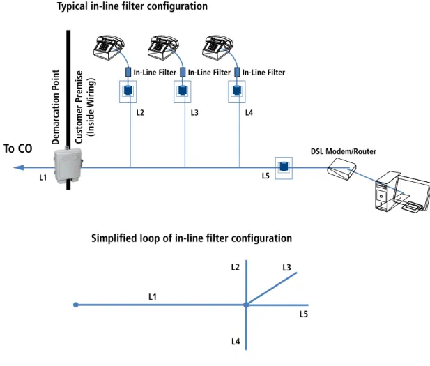
MicrofiltersA microfilter is a Low-Pass Filter (LPF) that isolates the low frequency signals on the line from the high frequency (DSL) signals and prevents interference between the two. Microfilters have Line and POTS ports and are typically installed ‘in-line’ with telephones, fax machines and/or answering machines, and can be easily installed by the customer.
Figure 2 shows a typical household loop configuration with microfilters. The loop is defined by main segment L1 from the central office to the Line Port at the customer premises, L5 segment from the Line Port at the home to the modem, and additional line segments (bridge taps) L2, L3, and L4 which connect the line port with 3 in-line filters. (Note: These segments may represent one of three con-nections: 1) an in-line filter terminated with a telephonic device; 2) an unterminated in line-filter; or, 3) unterminated telephone wiring in the home.). It should be noted that in-line filters are connected in parallel with the line to the modem; a parallel connection with the line has a very high possibility of significantly changing the impedance of the line.
L5 L3 L2
L4 L1
Simplified loop of in-line filter configuration Typical in-line filter configuration
In-Line Filter In-Line Filter In-Line Filter
To CO
L1L2 L3 L4
L5
DSL Modem/Router
Customer Pr
emise
(Inside W
iring)
Demar
cation P
oint
CPE Splitter
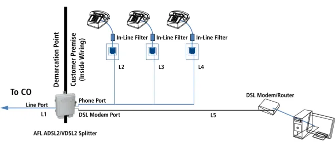
A CPE splitter has 3 connections: Line, DSL and POTS. It provides low pass filtering between the Line Port and POTS port and a HPF (high pass filter) or all pass filter between Line and DSL ports.
A typical Loop configuration of CPE splitter installation is shown in Figure 3. In this situa-tion, the loop for DSL signal is defined by main segment L1 between the central office and the Line Port at the home, and short segment L5 between Line Port and modem. It should be noted that segments L2, L3, L4 do not represent bridge taps to L1 and L5 because they are isolated by the CPE splitter.
Figure 3: Typical loop configuration in a CPE splitter installation
To CO
L1Line Port Phone Port
In-Line Filter In-Line Filter In-Line Filter
L2 L3 L4
L5
DSL Modem/Router
Customer Pr
emise
(Inside W
iring)
Demar
cation P
oint
DSL Modem Port AFL ADSL2/VDSL2 Splitter
VDSL2 POTS Splitters and Microfilters
CPE Splitter vs. In-Line FiltersComparing the installation configurations of a CPE Splitter (Figure 3) and multiple in-line filters (Figure 2), two main differences are noticed: 1. A multiple In-Line filter installation has an equivalent loop with bridge taps, whereas a CPE Splitter installation has an equivalent
straight line loop that eliminates bridge taps within the home.
2. Multiple In-Line filters are connected in parallel with line, while only one CPE splitter is connected to the line; therefore the resultant loading effect on the line is greater with in-line filters than with a CPE splitter.
Bridge (Bridged) Tap
A bridge tap is an unterminated branch in a cable, or any branch on a pair that is not a direct connection between the Line and the subscriber. For the purpose of this paper, we will refer to any ‘T’ connection in the copper pairs as a bridge tap, be it unterminated or terminated (with microfilter and/or telephone equipment).
Any signal transmitted on the main copper pair will also travel down the bridge tap. Open end of the bridge tap (or high impedance when filter is installed) will result of the signal being reflected back towards the main copper pair. In the voice band this reflection will result in echo; in the DSL band it will lower attainable data rates.
In the case of longer bridge taps (20- 40 ft) very drastic changes in data rates will occur due to significant changes in insertion loss and imped-ance. Impedance comparison for the two installation options is shown in Figure 4. Ideal input impedance to the modem is 100 Ohms.
Figure 4: Difference of impedance to the modem for loops with in-line filters with in line filters vs CPE splitter with configuration found in Appendix C
0 200 400 600 800 1000 1200 1400
frequ ency
[kH z]
3,00 0
6,00 0
9,00 0
12,0 00
15,0 00
18,0 00
21,0 00
24,0 00
27,0 00
Im
pe
da
nce
[O
hm
s
]
Modulus of impedance seen by modem for configuration H.1 Modulus of impedance seen by modem for configuration A and B
Calculations show that with an in-line filter configuration, bride tap segments of just 3 ft in length can change the impedance seen by the modem more than 50%. This change in impedance will result in high reflection and a smaller amount of power transferred to the modem; results will be significantly decreased VDSL2 data rates. Data rates will not be similarly affected with a CPE splitter due to the fact that the CPE splitter eliminates bridge taps, separating DSL and POTS at the input of home network.
In a configuration using in-line filters such as shown in the diagram below. A bridge tap of 40 ft would create notches (highest loss of the signal) around 4 MHz, 12 MHz, 20 MHz and 29 MHz. This would lead to downstream and/or upstream degradation depending upon what bands are impacted by the notches.
Figure 5: Insertion loss notches corresponding with a 40 foot bridge tap
In-Line Filter In-Line Filter
To Telco
1000 feet
40 feet
DSL Modem/Router
Customer Pr
emise
(Inside W
iring)
Demar
cation P
oint
-60 0 -40 -20
Frequency [Hz]
0
5⋅106 1⋅107 1.5⋅107 2⋅107 2.5⋅107 3⋅107
VDSL2 POTS Splitters and Microfilters
Data Rate Comparison between Configurations using CPE Splitter vs. In-Line Microfilter
Using a 2000 foot loop from the Telco Office to the Customer Premise:
• In-line filter configuration with a 3 foot bridge TAP between modem and phone line in-line filter as shown below. Measured 25% degradation in downstream data rate compared to configuration using a CPE Splitter.
• In-line filter configuration with a 20 foot bridge TAP between modem and phone line in-line filter as shown below. Measured 45% degradation in downstream data rate compared to configuration using a CPE Splitter.
In-Line Filter In-Line Filter
To Telco
2000 feet
3 feet
DSL Modem/Router
Customer Pr
emise
(Inside W
iring)
Demar
cation P
oint
In-Line Filter In-Line Filter
To Telco
2000 feet
20 feet
DSL Modem/Router
Customer Pr
emise
(Inside W
iring)
Demar
cation P
Measured Data Rates using Typical Home Wiring Configurations
The following tables compare measured VDSL2 training rates (17a profile) with CPE splitters and various in-line filter configurations. Refer to Appendices A, B and C for diagrams of the in-line filter installations.
AFL ADSL2/VDSL2 SPLITTER ADSL2/VDSL2 splitter placed at beginning of chain. Chain extends from POTS port of ADSL2/VDSL2. DSL Modem is home run from DSL port.
CONFIG A Daisy chain in-line filters 20 ft apart. Last jack has wall mount DSL filter with modem.
CONFIG B Daisy chain in-line filters 20 ft apart. First jack of chain has wall mount DSL filter with modem.
CONFIG C Daisy chain of POTS jacks 20 ft apart. First jack of chain has wall mount DSL filter with modem.
CONFIG D Daisy chain in-line filters 20 ft apart. Fourth jack of chain has wall mount DSL filter with modem.
* See Appendix A Daisy Chain Configuration for details on Configurations
VDSL2 Data Rates
(AFL Splitter versus various In-Line Filter Daisy Chain Configurations)
DS DS
DS
DS DS
DS
US US US US
US US
0 10 20 30 40 50 60 70 80 90 100
Baseline AFL ADSL2/VDSL2 Splitter Microfilter Config A Microfilter Config B Microfilter Config C Microfilter Config D
M
bi
VDSL2 Data Rates
(AFL Splitter versus In-Line Star configuration of various lengths with length to Filter of 20 ft)
DS
DS
DS DS DS
US US
US US US
0 10 20 30 40 50 60 70 80 90 100
Baseline AFL ADSL2/VDSL2 Splitter Microfilter Config F.1 Microfilter Config F.2 Microfilter Config F.3
M
b
it
s
VDSL2 Data Rates
(AFL Splitter versus In-Line Star configuration of various lengths with length to Filter of 40 ft)
DS DS DS DS DS S U S U
US US US
0 10 20 30 40 50 60 70 80 90 100
Baseline AFL ADSL2/VDSL2 Splitter Microfilter Config H.1 Microfilter Config H.2 Microfilter Config H.3
M
b
it
s
AFL ADSL2/VDSL2 SPLITTER NID-01V splitter placed at beginning of star TAP home run configuration. TAPs extend from POTS port of NID-01V. DSL modem is home run from DSL port. CONFIG F 5 TAP home run configuration with in-line filters on each end. 20 ft length taps.
* See Appendix B Star—20 foot phone lines for details on Configurations
VDSL2 Data Rates
(AFL Splitter versus In-Line Star configuration of various lengths with length to Filter of 20 ft)
DS
DS
DS DS DS
US US
US US US
0 10 20 30 40 50 60 70 80 90 100
Baseline AFL ADSL2/VDSL2 Splitter Microfilter Config F.1 Microfilter Config F.2 Microfilter Config F.3
M
b
it
s
VDSL2 Data Rates
(AFL Splitter versus In-Line Star configuration of various lengths with length to Filter of 40 ft)
DS DS DS DS DS S U S U
US US US
0 10 20 30 40 50 60 70 80 90 100
Baseline AFL ADSL2/VDSL2 Splitter Microfilter Config H.1 Microfilter Config H.2 Microfilter Config H.3
M
b
it
s
AFL ADSL2/VDSL2 SPLITTER ADSL2/VDSL2 splitter placed at beginning of star TAP home run configuration. TAPs extend from POTS port of NID-01V. DSL modem is home run from DSL port. CONFIG H 5 TAP home run configuration with in-line filters on each end. 40 ft length taps.
Appendix A—Daisy Chain Configuration To CO 2000 ft Customer Pr emise (Inside W iring) Demar cation P oint DSL Modem/Router 3 ft AFL NID To CO 2000 ft Customer Pr emise (Inside W iring) Demar cation P oint
20 ft 20 ft 20 ft 20 ft
Wall Mount DSL Filter
DSL Modem/Router
In-Line Filter In-Line Filter In-Line Filter In-Line Filter
AFL NID To CO 2000 ft Wall Mount DSL Filter DSL Modem/Router Customer Pr emise (Inside W iring) Demar cation P oint
20 ft 20 ft 20 ft 20 ft
In-Line Filter In-Line Filter In-Line Filter In-Line Filter
AFL NID To CO 2000 ft Customer Pr emise (Inside W iring) Demar cation P oint Wall Mount DSL Filter
20 ft 20 ft 20 ft 20 ft
To CO 2000 ft Customer Pr emise (Inside W iring) Demar cation P oint Wall Mount DSL Filter DSL Modem/Router
20 ft 20 ft 20 ft
In-Line Filter In-Line Filter In-Line Filter
20 ft In-Line Filter AFL NID To CO 2000 ft Phone Port 3 ft Customer Pr emise (Inside W iring) Demar cation P oint
DSL Modem Port
DSL Modem/Router
20 ft 20 ft 20 ft 20 ft 20 ft
AFL NID
Baseline AFL Splitter
Config A Config B
Appendix B Star—20-foot Phone Lines To CO 2000 ft Customer Pr emise (Inside W iring) Demar cation P oint DSL Modem/Router 3 ft AFL NID To CO 2000 ft Customer Pr emise (Inside W iring) Demar cation P oint Wall Mount DSL Filter DSL Modem/Router 20 ft 20 ft 20 ft 20 ft 20 ft In-Line Filter In-Line Filter In-Line Filter In-Line Filter AFL NID To CO 2000 ft Customer Pr emise (Inside W iring) Demar cation P oint Wall Mount DSL Filter DSL Modem/Router 20 ft 20 ft 20 ft 20 ft 3 ft In-Line Filter In-Line Filter In-Line Filter In-Line Filter AFLNID To CO 2000 ft Customer Pr emise (Inside W iring) Demar cation P oint 20 ft 20 ft 20 ft 20 ft Wall Mount DSL Filter DSL Modem/Router 3 ft AFLNID To CO 2000 ft Customer Pr emise (Inside W iring) Demar cation P oint Wall Mount DSL Filter DSL Modem/Router 20 ft 20 ft 3 ft In-Line Filter In-Line Filter 20 ft 20 ft In-Line Filter In-Line Filter Phone Port DSL Modem Port
AFL NID
Baseline AFL Splitter
Config F.1 Config F.2
Appendix C Star—40-foot Phone Lines To CO 2000 ft Customer Pr emise (Inside W iring) Demar cation P oint DSL Modem/Router 3 ft AFL NID To CO 2000 ft Customer Pr emise (Inside W iring) Demar cation P oint Wall Mount DSL Filter DSL Modem/Router 40 ft 40 ft 40 ft 40 ft 40 ft In-Line Filter In-Line Filter In-Line Filter In-Line Filter AFL NID To CO 2000 ft Customer Pr emise (Inside W iring) Demar cation P oint Wall Mount DSL Filter DSL Modem/Router 40 ft 40 ft 40 ft 40 ft 3 ft In-Line Filter In-Line Filter In-Line Filter In-Line Filter AFL NID To CO 2000 ft Customer Pr emise (Inside W iring) Demar cation P
oint 40 ft
40 ft 40 ft Wall Mount DSL Filter DSL Modem/Router 3 ft AFL NID To CO 2000 ft Customer Pr emise (Inside W iring) Demar cation P oint Wall Mount DSL Filter DSL Modem/Router 40 ft 40 ft 3 ft In-Line Filter In-Line Filter 40 ft 40 ft In-Line Filter In-Line Filter Phone Port DSL Modem Port
AFL NID
Baseline AFL Splitter
Config H.1 Config H.2
![Figure 4: Difference of impedance to the modem for loops with in-line filters with in line filters vs CPE splitter with configuration found in Appendix C0200400600800100012001400frequency[kHz]3,0006,0009,00012,00015,00018,00021,00024,000 27 ,0 00Impedanc](https://thumb-us.123doks.com/thumbv2/123dok_us/8505613.2277095/4.918.171.749.653.1001/figure-difference-impedance-splitter-configuration-appendix-frequency-impedanc.webp)

