REF.KIT #30-A2160 PN 00-02-1610
VISION DX
600 Series
Digital Sensor System
0120
EU Representative: CE Partner 4U Esdoornlaah 13 3951DB Maarn The Netherlands
Phone +31.434.442.524
Vision DX 600 Series
Digital Sensor System
Installation Instructions
00-02-1610 Rev. D
Midmark Corporation 675 Heathrow Drive Lincolnshire, IL 60008, U.S.A.
Phone +1 (847) 415-9800 Toll Free +1 (888) 924-3800
Fax: +1 (847) 415-9810 www.progenydental.com
Scope
This manual provides the technician with installing instructions for the following units and software:
Standalone Version of Vision DX
Factory-Integrated Version of Vision DX in Preva Plus, Preva Mobile Plus, VetVision Complete, and VetVision Complete Mobile
Preva to Preva Plus, Preva Mobile to Preva Mobile Plus, VetVision DC to VetVision Complete, and VetVision Mobile to VetVision Complete Mobile Upgrade Kits
Progeny Imaging
Installing the Sensor calibration files
NOTE: It is recommended that the installing technician review the instructions before attempting to install or upgrade any component.
Getting Assistance
Contact Progeny Technical Service at +1 (847) 415-9800 ext. 3 or Toll Free (U.S. and Canada) at +1 (888) 924-3800 ext. 2 for any questions, concerns or suggestions for improvement of this or any other guide.
To facilitate your service call, the following information should be ready and available: Your computer operating system (Windows Vista, Windows XP, Mac OS)
Version of Progeny Imaging software
Serial number of your Vision DX system and sensor
Table of Contents
Section 1: Introduction ... 6
Overview ... 6
Before You Begin ... 6
PC and Software ... 6
Check System Contents ... 6
Tools Required ... 8
Additional Documentation ... 8
Section 2: Standalone Version of Vision DX ... 9
Section 3: Factory-Integrated Vision DX into Preva Plus (or VetVision Complete) ... 11
Section 4: Factory-Integrated Vision DX into Preva Mobile Plus (or VetVision Complete Mobile) ... 15
Section 5: Preva to Preva Plus (or VetVision DC to VetVision Complete) Upgrade Kit ... 19
Section 6: Preva Mobile to Preva Mobile Plus (or VetVision DC Mobile to VetVision Complete Mobile) Upgrade Kit ... 24
Section 7: Hardware Options ... 30
Option 1: Integrated USB-to-CAT5 Extender (part #600-100) ... 30
Option 2: Standalone USB-to-CAT5 Extender (part #600-108) ... 31
Option 3: A/B Switch (For pass through application) (part #30-A2153) ... 32
Section 8: Progeny Imaging ... 35
Overview ... 35
Features and Functions ... 35
Progeny Imaging Components ... 35
Supported Image Acquisition Systems ... 35
Bridge to Third-party Applications ... 36
Recommended System Requirements ... 36
Before You Begin ... 37
Overview of the Installation Process ... 37
About the Progeny Installation Disk ... 37
Before Installing Progeny Imaging ... 38
Installation Configurations ... 38
Installing Progeny Imaging ... 40
Uninstalling Progeny Device Service ... 43
Logging in for the First Time ... 43
Progeny Imaging Database in Networked Configuration ... 44
Configure sharing for the Progeny Imaging directory in Windows Domain Network ... 45
Configure sharing for the Progeny Imaging directory on a Workgroup Network ... 47
Configure MS SQL Server for Network Access ... 48
Configuring Progeny Imaging to Use a Networked Database ... 50
Section 9: Sensor Calibration in Progeny Imaging ... 52
Section 1:
Introduction
Overview
The Vision DX Sensor System is an intraoral digital sensor system used with an intraoral X-Ray to capture digital images of human dentition.
The Progeny Vision DX Sensor System is available in two configurations: Standalone – Interface Module and Sensor, connected directly to a PC
Integrated – Integrated into and part of the Preva Plus or VetVision Complete system In addition, the integrated version of Vision DX is available as upgrade kit to existing Preva Plus or VetVision Complete systems.
This guide is intended to serve as an Installation Guide for both, the standalone and integrated configurations of the Progeny Vision DX Sensor System, using Progeny Imaging or other imaging software programs.
Before You Begin
PC and Software
You must have a dedicated PC with a 32-bit or 64-bit operating system. The operating system may be Windows XP Professional or Windows Vista, and at least one USB port must be available.
Image capture and management software must be installed on the computer(s) that will host the Vision DX Sensor System. If you are using Progeny Imaging Software, it must be installed on every PC that will interface with the Vision DX Sensor System. If you are not using Progeny Imaging, then compatible image capture and management software must be installed on all PC to be used. Contact your Dental Equipment Dealer or Progeny Technical Service for a list of compatible imaging software programs.
For Progeny Imaging software installation and use, refer to the documentation shipped with the Progeny Imaging Installation Disk, or contact Progeny Technical Service.
Check System Contents
Verify that all items listed on the Packing List are contained in your system order. If any item appears to be missing, contact Progeny Technical Service immediately.
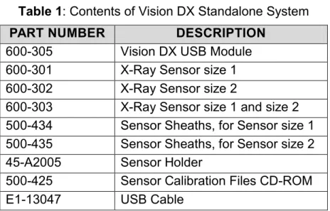
Table 1: Contents of Vision DX Standalone System
PART NUMBER DESCRIPTION
600-305 Vision DX USB Module
600-301 X-Ray Sensor size 1
600-302 X-Ray Sensor size 2
600-303 X-Ray Sensor size 1 and size 2 500-434 Sensor Sheaths, for Sensor size 1 500-435 Sensor Sheaths, for Sensor size 2
45-A2005 Sensor Holder
500-425 Sensor Calibration Files CD-ROM
E1-13047 USB Cable
Table 2: Contents of Vision DX Integrated System
PART NUMBER DESCRIPTION
600-306 Vision DX USB Module
600-301 X-Ray Sensor size 1
600-302 X-Ray Sensor size 2
600-303 X-Ray Sensor size 1 and size 2 500-434 Sensor Sheaths, for Sensor size 1 500-435 Sensor Sheaths, for Sensor size 2
45-A2004 Sensor Holder
500-425 Sensor Calibration Files CD-ROM
E1-13047 USB Cable
30-08128 USB Bus-powered Hub
Table 3: Contents of Optional Dual Host Switch
PART NUMBER DESCRIPTION
30-08137 USB Dual-Host Switch
600-100 USB Cable Extension Kit (integrated) 600-108 USB Cable Extension Kit (standalone)
Tools Required
No tools are required to install the Standalone Vision DX version. To install the Integrated Vision DX version the following tools will be needed together with all other tools required to install the Preva (VetVision DC):
Philips Screwdriver, #1 Philips Screwdriver, #2 3 mm Hex Wrench Diagonal Cutter
Additional Documentation
Complete, detailed instructions are found in Progeny’s technical support documentation. The manuals are identified as.
Table 4: List of the available literature
PART NUMBER DESCRIPTION
00-02-1610 Vision DX 600 Series Installation Guide 00-02-1594 Vision DX 600 Series User Guide 00-02-1604 Progeny Imaging Installation Guide
00-02-1598 Progeny Imaging User Guide, Human Applications 00-02-1605 Progeny Imaging User Guide, Veterinary Applications
These documents can be provided upon request in either printed or electronic forms. Feel welcome to contact the Progeny Technical Support Group with any question.
Section 2:
Standalone Version of Vision DX
In the standalone configuration, Vision DX consists of an X-Ray Sensor, Interface Module, and USB cables as shown on Figure 1, page 9.
Figure 1
The Interface Module connects directly to the computer selected to run both the software and the sensor system as shown on Figure 2, page 9.
Figure 2
To install the Standalone Vision DX Sensor System execute the following steps:
1. Plug the square end (Type B) of the provided USB cable into the square end connector of the Interface Module as shown on Figure 3, page 9.
2. Plug the Sensor connector into the receptacle on the front of the Vision DX Interface Module as shown on Figure 4, page 10.
Figure 4
3. Plug the flat end (Type A) of the USB cable from the Module into any USB port on the PC as shown on Figure 5, page 10.
Figure 5
If you have your Imaging software installed already, finish the installation of the Standalone Vision DX system by calibrating the sensor as it is described in Section 9 “Sensor Calibration in Progeny Imaging”, page 52. However, if you do not have your Imaging software installed or you are not sure, install the desired Imaging software and then proceed to Section 9 “Sensor Calibration in Progeny Imaging”, page 52.
To install Progeny Imaging as your Imaging software, continue with Section 8 “Progeny Imaging”, page 35.
Section 3:
Factory-Integrated Vision DX into Preva Plus (or VetVision
Complete)
In the factory-integrated configuration, Vision DX Interface Module is already integrated with the Preva Plus (or VetVision Complete) Articulated Arm and the Unpowered USB Hub is already installed into the Preva Plus (or VetVision Complete) control module.
Figure 6
To install the factory-integrated Vision DX Sensor System execute the following steps:
NOTE: Install the factory-integrated Vision DX system after the Preva Plus (or VetVision Complete) is installed.
1. Attach the sensor holder to the articulating arm by peeling off the tab and exposing the sticky tape (see Figure 7 on page 11).
Sensor holder
2. Plug the sensor connector into the Sensor Interface at the bottom of the Arm mount as shown on Figure 8, page 12.
Figure 8
3. Place the sensor into the sensor holder as shown on Figure 9, page 12.
Figure 9
4. Remove the access plate from the underside of the horizontal arm by removing the two Phillips head screws (see Figure 10 on page 12).
Figure 10
5. Locate the USB cable originating from the articulating arm and connect it to the USB cable located in the horizontal (see Figure 11 on page 13).
NOTE: Feed the excess USB cable into to the horizontal arm taking care not to damage or pinch the USB cable.
Figure 11
6. Re-install the access plate that was removed in step 4 on page 12.
7. Remove the cover from the Preva Plus (VetVision Complete) control unit.
8. Locate the free end of the USB cable originating from the horizontal arm. If it is secured with a cable tie, carefully cut the cable tie.
9. Plug the USB cable from the horizontal arm into J1 of the unpowered USB Hub (see Figure 12 on page 13).
Unpowered USB HUB
Bracket
J2 (Plug the 5 m USB cable here)
J1 (Plug USB cable from horizontal arm here)
Figure 12
10. Connect the 5 m USB extender cable (part #E1-13047) to J2 of the unpowered USB Hub (see Figure 12 on page 13).
11. Cut and clear a notch in the control cover using a set of diagonal cutters as shown on Figure 13, page 13.
12. Feed the 5 m USB extender cable through the notch in the bottom of the control unit cover and replace the cover.
13. Plug the 5 m USB cable from step 12 (page 14) into any port on the 4-port Hub. Make certain to energize the 4-port Hub with AC power adapter (see Figure 14 on page 14).
Figure 14
14. Plug the 4-port hub to an available USB port on the PC using the hub cable provided in the hub packaging (See Figure 15 on page 14).
Figure 15
If any of the additional hardware options were purchased, continue with Section 7 “Hardware Options”, page 30. If no additional hardware options were purchased and if you have your Imaging software installed already, finish the installation of the Integrated Vision DX system by calibrating the sensor as it is described in Section 9 “Sensor Calibration in Progeny Imaging”, page 52. However, if you do not have your Imaging software installed or you are not sure, install the desired Imaging software and then proceed to Section 9 “Sensor Calibration in Progeny Imaging”, page 52.
To install Progeny Imaging as your Imaging software, continue with Section 8 “Progeny Imaging”, page 35.
Section 4:
Factory-Integrated Vision DX into Preva Mobile Plus (or
VetVision Complete Mobile)
In the factory-integrated configuration, Vision DX Interface Module is already integrated with the Preva Mobile Plus (or VetVision Complete Mobile) Articulated Arm and the Unpowered USB Hub is already installed into the Preva Mobile Plus (or VetVision Complete Mobile) control module.
To install the factory-integrated Vision DX Sensor System execute the following steps:
NOTE: Install the factory-integrated Vision DX system after the Preva Mobile Plus (or VetVision Complete Mobile) is assembled.
1. Attach the sensor holder to the articulating arm by peeling off the tab and exposing the sticky tape (see Figure 16 on page 15).
Sensor holder
Figure 16
2. Plug the sensor connector into the Sensor Interface at the bottom of the Arm mount as shown on Figure 17, page 15.
3. Place the sensor into the sensor holder as shown on Figure 18, page 16.
Figure 18
4. Connect the extender USB cable (part #E1-13045-01) to the USB cable originating from the articulating arm (see Figure 19 on page 16).
Extender cable (E1-13045-01)
Figure 19
5. The other end of the extender USB cable (part #E1-13045-01) will be located in the front of the operator panel mounting plate (see Figure 20 on page 16).
Extender cable (E1-13045-01)
6. With the cradle removed, route the extender USB cable through the hole located on the bottom of the cradle. Then route the CAT5 cable through the opening in the cradle (see Figure 21 on page 17).
Figure 21
7. Re-attach the cradle
8. Attach the CAT5 cable to the control panel as shown on Figure 22, page 17.
Figure 22
9. Attach the control panel on to the cradle (see Figure 23 on page 17).
10. Attach the extender cable that was routed in step 6 (page 17) to any available USB port on the 4-port hub mounted to the back of the cradle as shown on Figure 24, page 18.
NOTE: Brand of 4-port hub may vary but installation procedure and mounting location does not change
Figure 24
11. Attach the 5 m USB extender cable (part #E1-13047) to the 4-port hub as shown on Figure 25, page 18.
Figure 25
12. Attach the other end of the 5 m extender cable (part #E1-13047) to any open USB port on the PC.
If any of the additional hardware options were purchased, continue with Section 7 “Hardware Options”, page 30. If no additional hardware options were purchased and if you have your Imaging software installed already, finish the installation of the Integrated Vision DX system by calibrating the sensor as it is described in Section 9 “Sensor Calibration in Progeny Imaging”, page 52. However, if you do not have your Imaging software installed or you are not sure, install the desired Imaging software and then proceed to Section 9 “Sensor Calibration in Progeny Imaging”, page 52.
To install Progeny Imaging as your Imaging software, continue with Section 8 “Progeny Imaging”, page 35.
Section 5:
Preva to Preva Plus (or VetVision DC
to VetVision Complete) Upgrade Kit
To upgrade an existing Preva (or VetVision DC) intraoral X-Ray system to Preva Plus (or VetVision Complete) a Vision DX upgrade kit must be use. The following upgrade kits are available: 600-401 Upgrade Kit with Sensor size 1 600-402 Upgrade Kit with Sensor size 2
600-403 Upgrade Kit with Sensors size 1 and size 2 600-404 Upgrade Kit without Sensor
NOTE: Upgrading from Preva to Preva Plus (or VetVision DC to VetVision Complete) can be accomplished only on X-Ray systems manufactured after July 1, 2008. These X-Ray units have been adapted to accept the integration of the Progeny Vision DX sensor system.
NOTE: The upgrade has to be accomplished after the Preva (or VetVision DC) is installed.
1. Remove the end caps (closest to the tube head) from the articulating arm by pulling them apart as shown on Figure 26, page 19.
2. Locate the cable tie that holds the end of the USB cable to the articulating arm – see Figure 27 on page 20.
Cable tie
Figure 27
3. Carefully cut the cable tie with a diagonal cutter.
NOTE: Do not to cut the USB cable jacket.
4. Plug the USB cable into J1 of the Sensor Interface PCB arm mount as shown on Figure 28, page 20.
Sensor Interface PCB J1
Figure 28
5. Press the two matching covers together and secure with the 3 mm x 16 mm screw provided in the package. Use a 3 mm hex wrench to tighten (see Figure 29 on page 20).
3mm x 16mm screw
6. Attach the sensor holder to the articulating arm by peeling off the tab and exposing the sticky tape (see Figure 30 on page 21).
Sensor holder
Figure 30
7. Plug the sensor connector into the Sensor Interface at the bottom of the Arm mount as shown on Figure 31, page 21.
Figure 31
8. Place the sensor into the sensor holder as shown on Figure 32, page 21.
Figure 32
9. Remove the access plate from the underside of the horizontal arm by removing the two Phillips head screws (see Figure 33 on page 21).
10. Locate the USB cable originating from the articulating arm and connect it to the USB cable located in the horizontal (see Figure 34 on page 22).
NOTE: Feed the excess USB cable into to the horizontal arm taking care not to damage or pinch the USB cable.
Figure 34
11. Re-install the access plate that was removed in step 9 on page 21. 12. Remove the cover from the Preva (VetVision DC) control unit.
13. Attach the unpowered USB Hub (part #30-08128) to the bracket adjacent to the Logic PCB. Use the two 3 mm x 5 mm screws provided (see Figure 35 on page 22).
Unpowered USB HUB
Bracket
J2 (Plug 5M USB cable here)
J1 (Plug USB cable from horizontal arm here)
Figure 35
14. Locate the free end of the USB cable originating from the horizontal arm. If it’s secured with a cable tie, carefully cut the cable tie.
15. Plug the USB cable from the horizontal arm into J1 of the unpowered USB Hub (see Figure 35 on page 22).
17. Cut and clear a notch in the control cover using a set of diagonal cutters as shown on Figure 36, page 23.
Figure 36
18. Feed the 5 m USB extender cable through the notch in the bottom of the control unit cover and replace the cover.
19. Plug the 5 m USB cable from step 18 (page 23) into any port on the 4-port Hub. Make certain to energize the 4-port Hub with AC power adapter (see Figure 37 on page 23).
Figure 37
20. Plug the 4-port hub to an available USB port on the PC using the hub cable provided in the hub packaging (See Figure 38 on page 23).
Figure 38
If any of the additional hardware options were purchased, continue with Section 7 “Hardware Options”, page 30. If no additional hardware options were purchased and if you have your Imaging software installed already, finish the installation of the Integrated Vision DX system by calibrating the sensor as it is described in Section 9 “Sensor Calibration in Progeny Imaging”, page 52. However, if you do not have your Imaging software installed or you are not sure, install the desired Imaging software and then proceed to Section 9 “Sensor Calibration in Progeny Imaging”, page 52.
To install Progeny Imaging as your Imaging software, continue with Section 8 “Progeny Imaging”, page 35.
Section 6:
Preva Mobile to Preva Mobile Plus (or VetVision DC Mobile
to VetVision Complete Mobile) Upgrade Kit
To upgrade an existing Preva Mobile (or VetVision DC Mobile) intraoral X-Ray system to Preva Mobile Plus (or VetVision Complete Mobile) a Vision DX upgrade kit must be use. The following upgrade kits are available:
600-401 Upgrade Kit with Sensor size 1 600-402 Upgrade Kit with Sensor size 2
600-403 Upgrade Kit with Sensors size 1 and size 2 600-404 Upgrade Kit without Sensor
NOTE: Upgrading from Preva Mobile to Preva Mobile Plus (or VetVision DC Mobile to VetVision Complete Mobile) can be accomplished only on X-Ray systems manufactured after July 1, 2008. These X-Ray units have been adapted to accept the integration of the Progeny Vision DX sensor system.
NOTE: The upgrade has to be accomplished after the Preva Mobile (or VetVision DC Mobile) is assembled.
1. Remove the end caps (closest to the tube head) from the articulating arm by pulling them apart as shown on Figure 39, page 24.
2. Locate the cable tie that holds the end of the USB cable to the articulating arm – see Figure 40 on page 25.
Cable tie
Figure 40
3. Carefully cut the cable tie with a diagonal cutter.
NOTE: Do not to cut the USB cable jacket.
4. Plug the USB cable into J1 of the Sensor Interface PCB arm mount as shown on Figure 41, page 25.
Sensor Interface PCB J1
Figure 41
5. Press the two matching covers together and secure with the 3 mm x 16 mm screw provided in the package. Use a 3 mm hex wrench to tighten (see Figure 42 on page 25).
3mm x 16mm screw
6. Attach the sensor holder to the articulating arm by peeling off the tab and exposing the sticky tape (see Figure 43 on page 26).
Sensor holder
Figure 43
7. Plug the sensor connector into the Sensor Interface at the bottom of the Arm mount as shown on Figure 44, page 26.
Figure 44
8. Place the sensor into the sensor holder as shown on Figure 45, page 26.
Figure 45
9. Connect the extender USB cable (part #E1-13045-01) to the USB cable originating from the articulating arm (see Figure 46 on page 26).
10. The other end of the extender USB cable (part #E1-13045-01) will be located in the front of the operator panel mounting plate (see Figure 47 on page 27).
Extender cable (E1-13045-01)
Figure 47
11. With the cradle removed, route the extender USB cable through the hole located on the bottom of the cradle. Then route the CAT5 cable through the opening in the cradle (see Figure 48 on page 27).
Figure 48
12. Re-attach the cradle
13. Attach the CAT5 cable to the control panel as shown on Figure 49, page 27.
14. Attach the control panel on to the cradle (see Figure 50 on page 28).
Figure 50
15. Attach the 4-port USB hub to the back of the cradle mount with the supplied Velcro (see Figure 51 on page 28). Make certain to energize the 4-port hub with AC power.
NOTE: Brand of 4-port hub may vary but installation procedure and mounting location does not change
Figure 51
16. Attach the extender cable that was routed in step 11 (page 27) to any available USB port on the 4-port hub as shown on Figure 51, page 28.
17. Attach the 5 m USB extender cable (part #E1-13047) to the 4-port hub as shown on Figure 52, page 28.
If any of the additional hardware options were purchased, continue with Section 7 “Hardware Options”, page 30. If no additional hardware options were purchased and if you have your Imaging software installed already, finish the installation of the Integrated Vision DX system by calibrating the sensor as it is described in Section 9 “Sensor Calibration in Progeny Imaging”, page 52. However, if you do not have your Imaging software installed or you are not sure, install the desired Imaging software and then proceed to Section 9 “Sensor Calibration in Progeny Imaging”, page 52.
To install Progeny Imaging as your Imaging software, continue with Section 8 “Progeny Imaging”, page 35.
Section 7:
Hardware Options
Option 1: Integrated USB-to-CAT5 Extender (part #600-100)
This extender provides for a longer cable run than permitted by USB cables. A USB to/from CAT5 Converter is used on both the computer end and the sensor end with a Category 5 Shielded Twisted Pair (STP) cable in between that can run up to 15 m (50 ft) in length.
In the cases where the PC cannot reach the Preva Plus control unit with the 5 m USB cable, an USB-to-CAT5 Extender may be used.
1. Attach the Integrated USB-to-CAT5 Converter (part #30-08141) to the bracket adjacent to the Logic PCB. Use the two 3 mm x 5 mm screws provided as shown on Figure 53, page 30.
NOTE: If an unpowered USB hub (part #30-06128) is already installed you will have to remove it first and replace it with the Integrated USB-to-CAT5 Converter as described in the step above.
Integrated USB-to-CAT5 Converter
J1 – Plug in the Horizontal arm USB cable here
8P8C modular connector – Plug the 15 m (50 ft) Cate-gory 5 STP cable here
Figure 53
2. Plug the USB cable from the horizontal arm into the Integrated USB-to-CAT5 Converter at J1 (see Figure 53 on page 30).
3. Plug one end of the 15 m (50 ft) Category 5 STP cable into the 8P8C modular connector on the Integrated USB-to-CAT5 Converter (see Figure 53 on page 30).
4. Plug the other end of the Category 5 STP cable to the CAT5-to-USB Converter (part #30-A2154) as shown on Figure 54, page 31.
CAT5 to USB convertor
Figure 54
When all additional hardware options are installed and if you have your Imaging software installed already, finish the installation of the Integrated Vision DX system by calibrating the sensor as it is described in Section 9 “Sensor Calibration in Progeny Imaging”, page 52. However, if you do not have your Imaging software installed or you are not sure, install the desired Imaging software and then proceed to Section 9 “Sensor Calibration in Progeny Imaging”, page 52.
To install Progeny Imaging as your Imaging software, continue with Section 8 “Progeny Imaging”, page 35.
Option 2: Standalone USB-to-CAT5 Extender (part #600-108)
This extender provides for a longer cable run than permitted by USB cables. A USB to/from CAT5 Converter is used on both the computer end and the sensor end with a Category 5 Shielded Twisted Pair (STP) cable in between that can run up to 15 m (50 ft) in length.
To install, plug the USB cable from the Vision DX control unit to the corresponding half of the Standalone USB-to-CAT5 Converter (see Figure 55 on page 31). Than, plug the 15 m (50 ft) Category 5 STP cable into the 8P8C modular connectors on both Standalone USB-to-CAT5 Converters, and than plug the second half of the Standalone USB-to-CAT5 Converter to the PC to as shown on Figure 55, page 31.
USB-to-CAT5 Extender PC connection
CAT5 Cable
USB cable to Vision DX
When all additional hardware options are installed and if you have your Imaging software installed already, finish the installation of the Integrated Vision DX system by calibrating the sensor as it is described in Section 9 “Sensor Calibration in Progeny Imaging”, page 52. However, if you do not have your Imaging software installed or you are not sure, install the desired Imaging software and then proceed to Section 9 “Sensor Calibration in Progeny Imaging”, page 52.
To install Progeny Imaging as your Imaging software, continue with Section 8 “Progeny Imaging”, page 35.
Option 3: A/B Switch (For pass through application) (part #30-A2153)
It may be necessary to use a dual host switch in the case that a Vision DX Integrated (Preva Plus) is installed in a pass through cabinet. The dual host switch allows for two computers in separate operatories to utilize the same integrated USB sensor.
1. Remove the unpowered USB Hub from the bracket inside the control unit if it is installed (see Figure 56 on page 32).
Unpowered USB hub.
Figure 56
2. Remove the control cover insert (see Figure 57 on page 32).
NOTE: Push from the inside of the cover to remove the insert.
3. Install the Dual-Host Switch Assembly (see Figure 58 and Figure 59 on page 33).
NOTE: Install from the inside of the control cover.
Dual Host Switch (part #30-06043)
Figure 58
Dual host Switch
Figure 59
4. Plug the USB cable from the Preva Plus Horizontal Arm into J2 on the Dual-Host Switch Assembly as shown on Figure 60, page 33.
5. Plug the two USB cables for each of the two PCs into J1 and J3 on the Dual-Host Switch Assembly (see Figure 60 on page 33).
Vision DX Integrated USB cable from the Preva
Plus Horizontal Arm
USB cables that connect to each PC
6. Route the two USB cables through the notch in the bottom of the Control Unit cover and replace the cover (see Figure 60 on page 33).
USB cables that connect to each PC
Figure 61
7. Plug one USB cable into a USB Port on each of the PCs. If the distance to any of the PCs is longer than 5 m, install the optional Standalone USB-to-CAT5 Extender as it is described in “Option 2: Standalone USB-to-CAT5 Extender (part #600-108)” on page 31.
When all additional hardware options are installed and if you have your Imaging software installed already, finish the installation of the Integrated Vision DX system by calibrating the sensor as it is described in Section 9 “Sensor Calibration in Progeny Imaging”, page 52. However, if you do not have your Imaging software installed or you are not sure, install the desired Imaging software and then proceed to Section 9 “Sensor Calibration in Progeny Imaging”, page 52.
To install Progeny Imaging as your Imaging software, continue with Section 8 “Progeny Imaging”, page 35.
Section 8:
Progeny Imaging
Overview
Features and Functions
Progeny Imaging acquires, displays, and stores digital dental X-Rays and intraoral video images. Progeny Imaging stores digital sensor images in DICOM format (Digital Imaging and Communications in Medicine). The DICOM format assures that each image contains patient identification and acquisition information.
You can use Progeny Imaging to:
Create login IDs for users of Progeny Imaging Manage patient records
Acquire, manipulate, and communicate images Configure devices to work with Progeny Imaging
NOTE: For information on using Progeny Imaging, refer to the Progeny Imaging User's Manual.
Progeny Imaging Components
Progeny Imaging consists of three main components: a graphical user interface, a database, and application folders. The graphical user interface is used to view and manipulate images. The database, which runs on MS SQL Server 2005 Express, stores user and patient information. The application folders store system settings, device configurations, and patient images.
Progeny Imaging needs to be installed on every computer where you want to view or acquire and store images. By default, the Progeny Imaging database is installed on the same computer where the graphical user interface is installed. This is the standalone (application) configuration.
You can also have the graphical user interface point to a central database on another computer within the office network. This is the networked (application) configuration.
Supported Image Acquisition Systems
Progeny Imaging works with Progeny Vision DX 600 Series, Vision DX 500 Series, and MPSe Digital Intraoral X-Ray image acquisition modules and sensors as well as with the Progeny Vivid Intraoral Video Camera.
The Progeny Vision DX 600 Series Digital Intraoral X-Ray Sensor System and the Progeny Vivid Video Camera are USB-based devices. These devices can only be installed directly to a
computer's USB 2.0 port (standalone device configuration) and cannot be shared across a network.
The Progeny Vision DX 500 Series and Progeny MPSe Intraoral X-Ray Sensor Systems are network-based devices. Two options exist for installing these devices:
Standalone configuration (default) – the sensor system is installed (in Standalone mode) directly to the computer's network port. In this configuration, the sensor system can only be used from the computer where it is connected. The computer in a Standalone configuration can access an office network or the Internet only if it has a second network port.
Networked configuration – the sensor system is installed using the default Standalone configuration and then reconfigured to be in Static IP mode. It can then be attached directly to a port of the same network (thru a hub or switch) where the client computer is. In this configuration, all computers and sensor system(s) are on the same network, and the sensor system can be accessed from computers in different rooms or the sensor system could be moved between different network ports. The network could be also attached to Internet and the computers may access the network and/or Internet without additional network port.
Bridge to Third-party Applications
PIBridge is an additional software application from Progeny Dental that enables you to use Progeny Imaging with 3rd-party applications, such as practice management software (PMS). With PIBridge, you can add Progeny Imaging's image acquisition and analysis capability seamlessly to your practice management software. After accessing a patient's records in your practice management application, you use PIBridge commands to "call" Progeny Imaging. At your command, Progeny Imaging opens for you to acquire images and create studies.
For information on PIBridge and using a 3rd party application with Progeny Imaging, contact Progeny Technical Support.
Recommended System Requirements
The performance of Progeny Imaging software is affected by the amount of RAM and storage memory available to the system for acquisition, displaying, storing, and printing digital X-Ray images. The recommended requirements are listed below as a guideline only.
As you review these guidelines, be aware that your patient volume, and the specific demands of your practice, may require you to adjust these guidelines accordingly. The system requirements of other programs operating on the same computer or network may affect these guidelines as well.
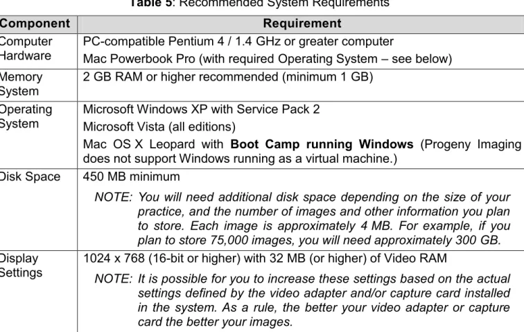
Table 5: Recommended System Requirements
Component Requirement
Computer
Hardware PC-compatible Pentium 4 / 1.4 GHz or greater computer Mac Powerbook Pro (with required Operating System – see below) Memory
System 2 GB RAM or higher recommended (minimum 1 GB) Operating
System Microsoft Windows XP with Service Pack 2 Microsoft Vista (all editions)
Mac OS X Leopard with Boot Camp running Windows (Progeny Imaging does not support Windows running as a virtual machine.)
Disk Space 450 MB minimum
NOTE: You will need additional disk space depending on the size of your practice, and the number of images and other information you plan to store. Each image is approximately 4 MB. For example, if you plan to store 75,000 images, you will need approximately 300 GB. Display
Settings
1024 x 768 (16-bit or higher) with 32 MB (or higher) of Video RAM
NOTE: It is possible for you to increase these settings based on the actual settings defined by the video adapter and/or capture card installed in the system. As a rule, the better your video adapter or capture card the better your images.
Before You Begin
Overview of the Installation Process
You must install Progeny Imaging on every computer where you want to view, acquire and store images. To install Progeny Imaging you do the following:
1. Remove any previous version of Progeny Imaging 2. Install the current version of Progeny Imaging 3. Open the software and login as the Administrator
4. (Additional step only If you are upgrading from Progeny Imaging 1.1.x.x): Remove Progeny Device Service
About the Progeny Installation Disk
Progeny Imaging is installed from the Progeny Installation disk. The disk also contains the help file and the database software MS SQL Server 2005 Express Edition. If MS SQL Server is not already installed on your computer, the Progeny Software Installer will install it.
Before Installing Progeny Imaging
Ensure that you are logged into your computer using an account that has Windows computer administrator privileges.
NOTE: Progeny Imaging requires that all users be logged into Windows as a computer administrator.
Installation Configurations
Progeny Imaging supports two different configurations of installing – Standalone and Networked. The Image Database and the Network-based image acquisition systems (such as Vision DX 500 Series and MPSe) could be installed in either mode. The Progeny Imaging graphical user interface and the USB-based image acquisition systems (such as Vision DX 600 Series and Vivid) can be installed only in standalone mode. Selecting an installation mode for one component does not limit the installation mode of any other component.
Standalone Configuration
Progeny Imaging component is installed in Standalone configuration if the component is accessible only from the computer where it is installed. Standalone also refers to the configuration in which a Network-based device (such as Vision DX 500 Series and MPSe) is connected to a dedicated network port on that computer.
In the standalone configuration shown on Figure 62 (page 38), the computer uses the Progeny Imaging database and application folders located on the computer. The computer has both Vision DX 600 Series and Vision DX 500 Series image acquisition systems connected to it. The Vision DX 600 Series is connected to a USB 2.0 port on the computer. The Vision DX 500 Series is connected to an available network port dedicated for that sensor system.
Figure 62 Networked Configuration
Progeny Imaging component is installed in Networked configuration if the component is accessible and shared between the computer where it is installed and the other computers connected thru network to that computer. In this case, the computer where the component is installed acts as Server, and all computers act as Clients for the functionality provided by the component. Networked also refers to the configuration in which a Network-based device (such
If the Progeny Imaging Database is installed in Networked configuration on a computer designated to act as a server, all computers that have Progeny Imaging graphical user interface can access the image database and can view centrally located patient images.
In the networked configuration shown on Figure 63 (page 39), Progeny Imaging is installed on each computer and on the office server. All computers use the Progeny Imaging database on the office server and the image acquisition module connected to the network hub.
Figure 63 Mixed (Standalone and Networked) Configuration
Many offices use a combination of standalone and networked configurations, similar to the example shown on Figure 64 (page 39).
Figure 64
In this example, Computer A has a Vision DX 600 Series image acquisition system (always standalone because it is USB-based). In addition, Computer A has two network ports, one of which is used for the Vision DX 500 Series sensor system that is installed in standalone configuration. The other network port on computer A is used to connect the computer to the office network, where it accesses the Progeny Imaging database, a second Vision DX 500 Series module set in networked configuration, and Internet, if the server provides Internet access. Computers B and C have one network port which they use to access the Progeny Imaging database and patient images on the office server, the Vision DX 500 Series on the office network hub and Internet, if the network provides access. All computers in this configuration can access the Vision DX 500 Series connected to the network, but only
Computer A can use the Vision DX 600 Series and Vision DX 500 Series modules connected directly to it.
Uninstalling Progeny Imaging
Always uninstall the earlier version of Progeny Imaging before installing the latest one when upgrading from a previous version of Progeny Imaging.
NOTE: Uninstalling Progeny Imaging or Progeny Device Service does not remove the Imaging database or MS SQL Server 2005 Enterprise Edition. These components will be used if you re-install Progeny Imaging.
To uninstall Progeny Imaging from a computer that has Windows XP operating system, follow the steps bellow:
1. From the Windows Start menu, select Control Panel. Then click on Add or Remove Programs icon.
2. In the Add or Remove Programs screen, select Progeny Imaging. 3. Click Remove.
If the computer has Windows Vista operating system, follow the steps bellow:
1. From the Windows Start menu, select Control Panel. Then click on Programs and Features icon.
2. In the Programs and Features screen, select Progeny Imaging. 3. Click Remove.
Installing Progeny Imaging
To install Progeny Imaging follow the steps bellow:
1. Insert the Progeny Imaging Installation disk into the computer’s optical (CD-ROM or DVD) drive. The Progeny Software Installer starts automatically (see Figure 65 on page 41).
NOTE: If the Progeny Software Installer does not start automatically, use the Windows Start menu and select Run. Then type the path to the program on the Progeny Imaging Installation disk.
Figure 65
2. In the Progeny Imaging Software Installer, click Install Progeny Imaging.
3. In the pop-up message, click "Yes" to confirm that you want to start the installation.
4. If your computer does not have the Visual C++ Runtime Libraries, you will be asked to install them. When asked, click Install.
5. If your computer does not have MS SQL Server 2005 Express Edition installed, you will see a license agreement. Read it and click Accept. You will see the Progeny Imaging screen. 6. In the Progeny Imaging screen, click "Next" (see Figure 66 on page 41).
7. In the Welcome screen, click "Next" (see Figure 67 on page 42).
Figure 67
8. In the Select Patient Target screen, select the appropriate type of practice based on your patient type. Then click "Next".
9. In the Confirm Installation screen, click Next to launch the installation. When the installation is complete, you will see the Installation Complete screen.
10. Click Close (see Figure 68 on page 42).
Figure 68
11. In the Progeny Software Installer, click Exit.
Uninstalling Progeny Device Service
Uninstall Progeny Device Service if you are upgrading from Progeny Imaging 1.1.x.x.
NOTE: Uninstalling Progeny Imaging and the Progeny Device Service does not remove the Progeny Imaging database or MS SQL Server 2005 Enterprise Edition. These components will be used if you re-install Progeny Imaging.
To uninstall Progeny Device Service from a computer that has Windows XP operating system, follow the steps bellow:
1. From the Windows Start menu, select Control Panel. Then click on Add or Remove Programs icon.
2. In the Add or Remove Programs screen, select Progeny Device Service. 3. Click Remove.
4. Delete the shortcut to Progeny Device Service from the Windows Programs menu. To delete the shortcut, display the Programs menu and right-click on Progeny Device Service. When the options menu appears, select "Delete".
If the computer has Windows Vista operating system, follow the steps bellow:
1. From the Windows Start menu, select Control Panel. Then click on Programs and Features icon.
2. In the Programs and Features screen, select Progeny Device Service. 3. Click Remove.
4. Delete the shortcut to Progeny Device Service from the Windows Programs menu. To delete the shortcut, display the Programs menu and right-click on Progeny Device Service. When the options menu appears, select "Delete".
Logging in for the First Time
Every time Progeny Imaging is launched, the Login window appears. You must log in to use Progeny Imaging. Progeny Imaging supports administrator and ordinary users.
Immediately after installing Progeny Imaging, you will log in as Administrator. Later, the Administrator can use the User Manager window to set up user IDs and passwords for other administrators and/or ordinary users.
Before Logging In ensure that you are logged into an account that has Windows computer administrator privileges.
NOTE: Progeny Imaging requires that all users to be logged into Windows as a computer administrator.
To Log in for the First Time
1. On your computer's desktop, double-click the Progeny Imaging icon, or select Progeny Imaging from your Windows Start menu.
2. In the Login screen User ID field, type Administrator (see Figure 69 on page 44).
NOTE: If you are logging into the application in another language, you must use the localized operating system's version of the "Administrator" login.
Figure 69
3. Leave the Password field blank.(No Password required) 4. Click Login.
Progeny Imaging Database in Networked Configuration
By default, Progeny Imaging uses the database that is installed on the same computer that runs the Progeny Imaging graphical user interface (GUI). However, you can choose to have Progeny Imaging use a database on one a server (or a computer designated to be the server) on the office network. This involves configuring sharing and remote access for the database and configuring of all Progeny Imaging GUIs to use the database on the server.
By default Progeny Imaging stores patient images on the same computer where the Progeny Imaging GUI is installed. You cannot change or relocate the image storage location. However, if you choose to have the Progeny Imaging database on a server (or a computer designated to be the server), you have to configure the images folder on the server to be shared.
Configuring the database for use on a network requires the following tasks to be executed on the server computer (or the computer designated to be the server):
Configure sharing for the Progeny Imaging directory Configure MS SQL Server to allow remote access
NOTE: Progeny Imaging requires that your office network to be set as a workgroup (Peer-to-Peer, P2P) or as a Windows domain (client-server). In all cases, all
NOTE: Progeny Imaging has to be installed and configured on the server (or the computer designated to be the server) and on all client computers. Take note of the server computer (machine) name as it will be used during the configuration of all client computers.
If the Progeny Image Database is intended to be used in Standalone configuration, continue with Section 9 “Sensor Calibration in Progeny Imaging” on page 52.
Configure sharing for the Progeny Imaging directory in Windows Domain Network
To Configure Sharing for the Progeny Imaging Directory on a Windows Domain Network follow the steps below:
1. In Windows Explorer navigate to the folder at C:\Program Files\Progeny. 2. In the Progeny folder, highlight the Progeny Imaging folder.
3. Right click and select Sharing and Security (see Figure 70 on page 45).
Figure 70
4. In the Progeny Imaging Properties box, select the Sharing tab. 5. Click Share this folder.
6. Click Permissions. 7. Click Add.
9. In the Select Users, Computers, or Groups box, click Find Now (see Figure 71 on page 46).
Figure 71
10. Select Network Service.
11. Click OK (see Figure 72 on page 46).
Figure 72
12. Click OK.
13. In the Permissions for Progeny Imaging box, select Allow for Full Control (see Figure 73 on page 46).
14. Click OK. 15. Click OK.
The Progeny Imaging folder icon should indicate that the folder is now shared.
Configure sharing for the Progeny Imaging directory on a Workgroup Network
To Configure Sharing for the Progeny Imaging Directory on a Workgroup (Peer-to-Peer, or P2P) Network follow the steps below:
1. Navigate to the folder at C:\Program Files\Progeny.
2. In the Progeny folder, highlight the Progeny Imaging folder. 3. Right click and select Sharing and Security.
4. In the Progeny Imaging Properties box, select the Sharing tab (see Figure 74 on page 47).
Figure 74
5. Click to select the sentence link: If you understand the security risks but want to share files without running the wizard, click here.
6. Select Just enable file sharing and click OK (see Figure 75 on page 47).
7. The Sharing tab now shows that Progeny Imaging is shared. Select Allow network users to change my files and click OK (see Figure 76 on page 48).
Figure 76
8. In the warning about share name length, click OK.
Configure MS SQL Server for Network Access
To Configure MS SQL Server for Network Access follow the steps below:
1. From the Windows Start menu, select Programs > Microsoft SQL Server 2005 > Configuration Tools > SQL Server Configuration Manager.
2. In the SQL Server Configuration Manager, expand SQL Server 2005 Network Configuration.
3. Click Protocols for SQLEXPRESS (see Figure 77 on page 48).
Figure 77
4. Verify that Shared Memory, Named Pipes, and TCP/IP are Enabled. If any of these items are not enabled, select, right-click, and enable them. Ignore any warnings that are
6. Click Client Protocols.
7. Verify that Shared Memory, Named Pipes, and TCP/IP are Enabled. If any of these items are not enabled, select, right-click, and enable them. Ignore any warnings that are displayed.
8. Close the SQL Server Configuration Manager.
9. From the Windows Start menu, select Programs > Microsoft SQL Server 2005 > Configuration Tools > SQL Server Surface Area Configuration.
10. Near the bottom of the screen, click Surface Area Configuration for Services and Connections.
11. Expand SQLEXPRESS.
12. Click Service (see Figure 78 on page 49).
Figure 78
13. In the Service status field, verify that the service is running. If the service is not running, click Start. Also, if the service is running, but you made changes in the SQL Server Configuration Manager, click Stop, then click Start.
14. Click Remote Connections (see Figure 79 on page 50).
Figure 79
15. Click Local and remote connections.
16. Click Using both TCP/IP and named pipes. 17. Click Apply.
18. Click SQL Server Browser. 19. Click Service.
20. In the Service status field, verify that the service is running. If the service is not running, select Automatic from the Startup Type drop-down list. Click "Apply", and then click "Start". 21. Click OK to close Surface Area Configuration for Services and Connections.
Configuring Progeny Imaging to Use a Networked Database
If you have chosen to network the Progeny Imaging database, you must configure the Progeny Imaging on each computer to use that networked database. You must restart the Progeny Imaging for this configuration to take effect.
NOTE: Before Configuring Progeny Imaging to use a Database on the Network, Progeny Imaging on the server computer (or the computer designated to be the server) has to be installed, Progeny Imaging folder on that computer has to be configured to allow sharing, and the Progeny Imaging database has to be configured to be used on a network.
To configure Progeny Imaging on a computer to Use a Database on the Network follow the steps bellow:
1. Select Tools > Options in Progeny Imaging (after log into Progeny Imaging). 2. In the Options screen, select the Database tab.
3. Select Networked to indicate that you are using a Progeny Imaging database that is located on another computer on the office network.
4. Click Find Servers and select the computer name that contains the Progeny Imaging database that you want to connect to.
5. Click Test for Database to verify that your computer can connect to the database. If the LED graphic on the Test for Database button turns green, then the computer you selected has an accessible Progeny Imaging database.
6. Before the change to the database takes effect, Progeny Imaging needs to restart. Click OK to restart Progeny Imaging.
Section 9:
Sensor Calibration in Progeny Imaging
Each Vision DX 600 Series Sensor comes with an individual calibration file unique to the sensor’s Serial Number. The calibration file must be installed before Progeny Imaging will recognize the sensor and prepare it to acquire images. To install the calibration file follow the steps bellow:
1. Open Progeny Imaging Software and log-in. In the top Tool Bar, find the Device Selection Menu. Select “Default Vision DX USB” (see Figure 80 on page 52).
Figure 80
2. When you select the Default Vision DX USB sensor from the Device Menu, the software will search for the sensor and its calibration file.
3. The Manage Vision DX Sensor Calibration File window will automatically open on your display (see Figure 81 on page 52).
Figure 81
4. Place the Calibration File CD for your sensor in to the CD/DVD drive of your PC now. 5. Click Add Calibration (see Figure 81 on page 52).
6. A new window will open (see Figure 82 on page 53).
Figure 82
7. Click the Browse Button (see Figure 82 on page 53) and navigate to My Computer. 8. Highlight the entry for “Progeny Sensor” (see Figure 83 on page 53).
NOTE: Do not expand the file!
Figure 83
10. The Navigation Window will close and the Progeny Sensor Serial Number will now appear in your New Sensor Calibration File Screen (see Figure 84 on page 54).
Figure 84
11. Click OK (see Figure 84 on page 54).
12. A confirmation Pop Up will appear on screen. Click Yes.
13. The configuration screen will close and return to the Manage Progeny Vision DX Sensor Calibration Menu. The Sensor Serial Number will now populate the screen and be highlighted in blue, and a green light will appear beside the Verify Calibration bar at the top of the menu. Click Close.
Section 10:
Configuring Progeny Imaging to Publish to a PACS Server
Patient images acquired in Progeny Imaging can be published (sent) to a PACS server. In order to enable publishing to a PACS server, the PACS.xml file has to be edited with the information about the PACS server.
NOTE: Set PACS.xml content on all computers with Progeny Imaging installed.
NOTE: Communication with the PACS server is uni-directional. Progeny Imaging receives no return communication from the PACS server indicating that the images were received.
When Progeny Imaging is installed, the PACS.xml file contains the lines shown below. If Progeny Imaging has previously been configured to send images to a PACS server, the PACS.xml file will contain values for the previously configured PACS server.
<?xml version="1.0" encoding="utf-8"?> <PACS>
<attribute ViewPublish="true" /> <attribute DServerIP="127.0.0.1" /> <attribute DTitle="PACS SERVER" /> <attribute DServerPort="2001" /> <attribute IsQuiet="true" /> <attribute IsSensitive="true" /> </PACS>
Before Configuring PACS Publishing be sure that you know the IP address, port, and machine name of the PACS server. To Configure PACS Publishing follow the steps bellow:
1. Verify that <attribute ViewPublish="true" /> is set to true.
2. Change 127.0.0.1 (or other IP address) in <attribute DServerIP="127.0.0.1" /> to the IP address of the PACS server where you intend to publish images.
3. Change PACS SERVER (or other PACS server name) in <attribute DTitle="PACS SERVER" /> to the machine name of the PACS server where you intend to publish images. 4. Change 2001 (or other port number) in <attribute DServerPort="2001" /> to the port number
of the PACS server where you intend to publish images. 5. Verify that <attribute IsQuiet="true" /> is set to true. 6. Verify that <attribute IsSensitive="true" /> is set to true. 7. Save the xml file, but do not change the file name.