Proceedings of the
Sixth International Workshop on
Graph Transformation and Visual Modeling Techniques
(GT-VMT 2007)
A Subgraph Operator for Graph Transformation Languages
Daniel Balasubramanian, Anantha Narayanan, Sandeep Neema, Feng Shi, Ryan Thibodeaux, and Gabor Karsai
12 pages
Guest Editors: Karsten Ehrig, Holger Giese
Managing Editors: Tiziana Margaria, Julia Padberg, Gabriele Taentzer
A Subgraph Operator for Graph Transformation Languages
Daniel Balasubramanian, Anantha Narayanan, Sandeep Neema, Feng Shi, Ryan Thibodeaux, and Gabor Karsai
Institute for Software-Integrated Systems Vanderbilt University
Nashville, TN 37235, USA
Abstract: In practical applications of graph transformation techniques to model transformations one often has the need for copying, deleting, or moving entire sub-graphs that match a certain graph pattern. While this can be done using elementary node and edge operations, the transformation is rather cumbersome to write. To simplify the transformation, we have recently developed a novel approach that al-lows selecting subgraphs from the matched portion of the host graph, applying a filter condition to the selection, and performing a delete, move, or copy operation on the filtered result in the context of a transformation rule. The approach has been implemented in the GReAT language and tested on examples that show the practical efficacy of the technique. The paper describes the technique in detail and illustrates its use on a real-life example.
Keywords:model transformations, graph transformations
1
Introduction
Practical model-driven software development necessitates software tools that transform models, and these tools are often implemented using graph transformation principles. Graph transforma-tion formalisms (e.g. single and double pushout [Roz97]) are based on node and edge matching, followed by creation of new nodes and edges, and/or removal of matched nodes and edges. In real-life applications, where the model transformations were implemented using graph transfor-mation rules, we have observed the need for a more sophisticated operation that can move, delete, or copy entire subgraphs after the match has been computed.
The specific problem can be described as follows. We have a graph transformation language that supports graph rewriting rules; the left hand side of the rule is matched against a host graph, and if the match is successful, then the actions specified by the right hand side are ex-ecuted. These actions can include deleting and inserting new edges and nodes. We argue that these elementary graph modification operations are often very low level, and practical users may want to use more complex, subgraph-oriented operations. The problem is especially apparent in graph transformation languages where the pattern nodes and edges could have cardinalities (like GReAT [AKN+06]), resulting in multiple matches from one activation of a rule. In this case, one has to create many simple rules to iterate over the results of the matching, as well as relating elements of different matches: clearly a cumbersome and error prone task.
‘green’. If we want to find all the ‘red’ nodes and the edges that connect them (but only them), this can be done with a simple graph pattern. However, moving these ‘red’ nodes plus the edges between them into a different model container while discarding any ‘red-green’ edges requires a rather non-trivial sequence of operations (consisting of simple node and edge addition and deletions).
Motivated by this and similar examples, we have developed an approach for specifying (‘se-lecting’) subgraphs from the result of the ‘match’ phase of the rule execution. These resulting subgraphs can then be deleted, copied, or moved to a different part of the graph. We have im-plemented this feature in the context of the GReAT language. The paper revisits the GReAT rule execution behavior, introduces the new ‘group’ concept and how it has extended the rule execution mechanism, presents a detailed example, describes related results, and summarizes the results and discusses potential research directions.
2
Background
The GReAT toolkit is an integrated environment for the specification and execution of model transformations using graph transformation rules. The GReAT language is a graphical language for specifying the transformation rules in terms of the meta-models of the source and target languages. In this section, we will review the basics of the GReAT language.
2.1 The GReAT Language
The meta-models of the source and target languages of the transformation are specified using UML class diagrams and added as packages in GReAT. In addition to this, GReAT allows users to add additional packages to specify cross-domain links and temporary links using the UML notation. Along with rule construction ingredients such as Blocks and Rules, these form the core concepts of the GReAT language, which can be subdivided into the following three sub-languages:
• Pattern Specification Language
• Transformation Rule Language
• Sequencing and Control-Flow Language
Pattern Specification Language
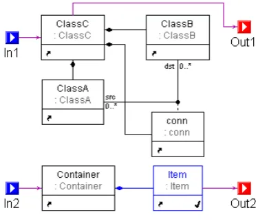
Figure 1: Example GReAT Rule
requiring the absence of a node or edge is called a negative application condition, and it is specified by using a pattern cardinality of zero for the appropriate elements.
Transformation Rule Language
The basic transformation entity of a GReAT transformation is called atransformation rule. A rule consists of a graph pattern specified using the pattern specification language and anaction on the pattern elements or newly created elements. Three types of actions are allowed: Bind, specifying that the element is to be matched in the host graph;CreateNew, specifying that the element should be newly created; andDelete, specifying that the element must be matched and then deleted from the graph. The rule interacts with other rules in the transformation using an Input Interfacefor receiving nodes matched in a previous rule and an Output Interfacefor passing elements to the next rule. A boolean expression can be inserted as aGuardto enforce the execution of a rule only under certain conditions. In addition, a special element calledAttribute Mappingcan be added to supplement the rule with C++ code. The Attribute Mapping code can be used to perform additional functions such as performing computations and setting the values of attributes for the existing or newly created objects. Note that a rule may generate multiple matches. For instance, if classC contains two instances of classA and two instances of classB, with the appropriate pairs connected via separate instances of the ‘conn’ association, the pattern matching yields two matches and the rule actions will be executed for each match. Each rule can also be configured to be executed for one, randomly selected match or for all the possible matches. Figure1shows an example GReAT rule with the input ports on the left and the output ports on the right. The nodeItemis marked with the CreateNewaction (indicated by the tick mark on the bottom right), and the rest of the nodes are marked withBind.
are matched first.)
The basic unit on which a rule operates is called a packet, which consists of nodes of the host graph to be bound to the input ports of the rule, one-to-one. When a rule fires, the pattern matching algorithm finds the matching subgraphs in the host graph, depending on the pattern specified in the rule. As mentioned above, a single rule execution may find multiple matches. From our example, given a classC, there could be multiple classB and classA objects associated via a conn, all being the children of the classC. Once these matches are found, the rule actions are executed for each match. For each match and action execution output packets are generated and placed at the output ports of the rule. The nodes bound to the output ports of the rule will provide the output packet(s) of the rule, and that will subsequently function as the input packet(s) of the next rule in the sequence of rules. In the case of the first rule, the nodes forming the input packet are specified by the user.
Sequencing and Control Flow Language
The sequencing and control flow language allows users to compose a series of rules specified using the transformation rule language. The sequencing allows users to connect multiple rules in a sequence such that each rule is executed in the order determined by the direction of the connections between the ports of the rules.
For the sake of convenience and manageability, rules can be composed in a hierarchy by placing a set of rules in aBlockor aForBlock. When a sequence of rules is placed in aBlock, each rule processes all its input packets and then passes the produced set of output packets to the next rule. In the case of aForBlock, each input packet of the parentForBlockpasses through all the rules before the next packet is processed. Blocks also allow recursion by connecting the output of the last rule in the block to the input interface of the block.
Conditional execution of rules can be specified by using the Test andCaseblocks. A Test block contains multiple Caseblocks, each specifying a desired match and a set of connected output ports, but noCreateNewandDeleteelements. The output(s) of theCasesare connected to the output(s) of the parentTest. EachCaseis tried, and the output produced by the successful one is place on the output interface of theTest.
3
The Group Operator
As it was discussed in section2, our current implementation for a graph re-writing rule’s execu-tion works in two sequential steps:
• Step 1: Find all the valid matches in the host graph for the given pattern (i.e., match the LHS of the rule in the host graph) and the given binding for the input ports.
• Step 2: For each match, independently, apply the rule action(s). This can include deleting elements, creating new elements, and changing attributes.
on each match; furthermore, there exists no mechanism by which one can access any informa-tion about other matches while processing a specific match. This can sometimes pose a severe limitation to the types of transformations one can write.
For instance, the user may need the ability to operate on an entire subgraph (composed from multiple matches) as a whole rather than on individual elements. If this subgraph may contain an arbitrary number of elements, then the graph pattern cannot be specified as a simple rule. What is needed is a way to find smaller pieces of the subgraph, and then combine these pieces to form the entire subgraph. In terms of GReAT this means we need a way to combine multiple matches of a rule, and then perform the rule’s action on these combined matches.
To achieve this capability, we had to extend the existing GReAT language. The solution was the introduction of a new syntactic element known as a ’Group’ into the language. A single Groupelement can be inserted into any rule, which allows the user to select an arbitrary set of pattern elements from that rule. AGroupelement is associated with a set of rule elements (pattern nodes and edges), but the only action allowed on these elements isBind. The elements in this set are then used to form the subgraphs mentioned in the previous paragraph. It is important to note that the introduction of aGroupelement into a rule does not affect the pre-existing semantics of pattern matching in any way; that is, the set of matches found by a rule is the same regardless of whether or not that rule contains aGroupelement. AGroupaffects the semantics of a rule only after the pattern matching phase of that rule’s execution, at which point theGroupis used to specify how to form the set of subgraphs (also called subgroups to emphasize the relationship with theGroupelement). The user has the ability to control the way in which matched elements are added to the subgroups by specifying ’filtering criteria’ for theGroupthat determine whether a matched element should be added to a subgroup or not. After all subgroups have been formed, then normal rule execution proceeds, with the exception that actions are performed for each subgroup (instead of for each match per the default behavior).
The precise semantics of a transformation rule that contains aGroupelement are informally described below:
• Step 1: Find all the valid matches in the host graph for the given pattern and given bindings. A match contains one matched element from the host graph for each pattern element.
• Step 2: After all the matches are found, insert a subset of the matched elements into a single subgroup based on the user specified criteria. These criteria are boolean expressions that compare matched elements of the current match to elements already inserted into subgroups; if the expressions evaluate to true, then the matched elements are inserted into the subgroup against which the expressions were evaluated. If the expressions evaluate to false for all existing subgroups, then the matched elements are inserted into a newly created subgroup.
• Step 3: Iterating over the subgroups, for each subgroup, execute the regular rule actions. Note that these actions apply to rule elements that are not part of theGroup, and they in-clude actions like creating new elements, and changing attributes. Matched (non-grouped) elements that are slated for deletion are removed at this time as well.
Figure 2: Signal Flow Model
– Bind: No action will be taken on any of the objects in the subgroup.
– Move: All of the objects in the subgroup will be moved into a single container: a node that has a ’containment’ relationship with theGroupexpressed in the rule. If this container is found via the matching process, then it must be a unique node. If this container is newly created, then it is unique (per Step 3). Edges whose endpoints are in different subgroups (or one of them is outside of all subgroups) are removed.
– Copy: All objects of the subgroup will be copied into all containers that have a ’con-tainment’ relationship with theGroupexpressed in the rule. Edges whose endpoints are in different subgroups (or one of them is outside of all subgroups) are removed.
– Delete: All objects in the subgroup will be deleted.
Steps 3 and 4 describe how the introduction of the group operator gives the ability to apply a single rule action across multiple matches. Further, step 4 describes two abilities that were not present in GReAT before the introduction of the Groupoperator: the ability to copy or move entire subgraphs. While this moving and copying ability is trivial in the case that only a single object is moved or copied, moving an entire subgraph, which includes a number of nodes and edges, is a non-trivial task and requires the use of a group-like operator. This is especially true if one does not know a priori the number of elements that will have to be moved.
The next section describes an example of theGroupoperator in a transformation.
4
Example of the Group Operator
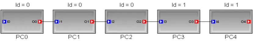
This example, drawn from the domain of signal processing, demonstrates how to use theGroup operator in a transformation. Suppose we have a signal flow chain with five primitive compo-nents, as shown in Figure2.
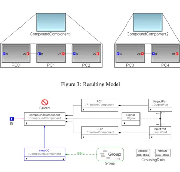
Figure 3: Resulting Model
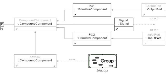
Figure 4: Group Rule
Figure4shows a GReAT transformation rule with aGroupelement that will accomplish this transformation. The incoming context for this rule is the compound component in which the signal flow chain is found. Figure5shows this transformation rule using a special visualization, highlighting only those elements that belong to the Group(PC1, PC2 and Signal). As can be seen in the rule shown in Figure5, the Group element contains three elements: two primitive components and the association class Signal. The action of the Group is “move”, meaning that objects bound to pattern variables contained in the Group (i.e., PC1, PC2, and Signal) are moved to the Compound Component “newCC”. The execution order of the rule is:
• Step 1: Pattern matching. Find all matches for the pattern described in the rule and apply the Guard to discard matches in which two primitive components with different Id-s are bound to PC1 and PC2. The code in the Guard is:
return (PC1.Id()==PC2.Id());
Figure 5: Group Rule visualized in Set Mode
{(PC0, PC1), (PC1, PC2), (PC3, PC4)}
• Step 2: Form the subgroups. Host graph elements that are part of the same match will all be inserted into the same subgroup, and the subgroups are formed using the user specified grouping criteria. The grouping criteria code for our example above is the following:
return (the_PC1.Id()==other_PC2.Id());
This code is an attribute of theGroupand works as follows. PC1 and PC2 are prefixed with “the ” and “other ”, respectively. These special prefixes give the ability to compare model elements that are part of different matches. The “the ” prefix refers to a graph element (bound to a pattern element) found in the current match that is being considered for insertion into a subgroup, while the “other ” prefix refers to graph elements that are already contained in a subgroup. In our example, the code returns true (and results in the insertion of the graph elements fromGroupsof two different matches into the same subgroup) if the Id of primitive PC1 in one match is the same as the Id of the primitive PC2 in a different match. The two subgroups formed in our example will be:
Group 1: PC0, PC1, PC2 (and the connections between them) Group 2: PC3, PC4 (and the connections between them)
• Step 3: Apply the regular rule action, which in our example is the creation of new objects. After the subgroups are formed in step 2, a new CompoundComponent object is created for each subgroup.
into the newly created CompoundComponent from Step 3. Note that the edge that did exist between PC2 and PC3 is deleted due to the fact that those two pattern classes were inserted into different subgroups.
5
Group Implementation
Using aGroupin a transformation rule requires that the rule
1. specifies theGroupand the elements it contains,
2. specifies the grouping criteria for the matches, and
3. specifies the action to be performed on the Group.
We have implemented Groups using the Set concept of GME [GME]. A Set is a universal container that can hold any number of arbitrary elements. In this manner, aGroupcan contain any type and number of pattern nodes and edges normally found in a transformation rule. The visualization interface of GME allows the user to specify which pattern classes are part of the Groupwithout drawing any explicit edges or associations (see previous figure).
In addition to specifying which elements of a rule belong to the Group, one must also specify the grouping criteria, which determine the subgroup into which each match should be placed. These criteria are written as boolean expressions that evaluate to either true or false, and are added as an attribute to theGroup element. The expressions are used to compare each match to matches that have already been placed into a subgroup; if the expressions evaluate to true, then the current match is added to the subgroup against which the criteria were evaluated. If the expressions evaluate to false for all existing subgroups, then the current match is inserted into a newly created subgroup. The elements of two distinct matches are identified in the grouping criteria by prefixing “the ” and “other ” to the class names of the elements. For instance, to place all instances ofClassAthat have the sameInvoiceNumberinto oneGroup, the expression would be: the ClassA.InvoiceNumber() = other ClassA.InvoiceNumber().
It should be noted that the distinct pattern matches may share common elements, and it could happen that the grouping criteria allow the insertion of the same element into two different sub-groups. As this could lead to erroneous rule execution, we believe this is an error that should result in raising exception. We are currently investigating how exception handling could be in-corporated into the language.
Once theGrouphas been completely specified, the action for theGroupcan be set to Bind, Move,Copy, orDeleteby selecting the desired value for theGroupActionattribute. The effect of these actions was described earlier in section3.
Currently,Groupshave been fully implemented in the GR-Engine [AKN+06], our interpreter for performing model transformations, and we have a prototype implementation in our code gen-erator. The previous version of the GR-Engine had an architecture as shown in Figure6, except without the Group Manager module. Because of the loose coupling between the Pattern Matcher and the Effector, implementingGroupsprimarily consisted of inserting a ‘Group Manager’ mod-ule between the two and defining the appropriate interfaces between the modmod-ules.
Figure 6: Modified GR-Engine Architecture
• The Pattern Matcher functions exactly as before, finding all valid matches. After all matches are found, they are passed to the Group Manager.
• Using the grouping criteria given by the user, the Group Manager forms the set of sub-groups. After all subgroups are formed, they are passed to the Effector using a newly defined interface created to handle subgroups.
• For each subgroup, the Effector first performs the regular rule action and then performs theGroupaction (as previously described).
6
Related Work
Transformations on hierarchical subgraphs have been approached previously by Hoffman and then Janssens. Hoffman [DHP02] introduced transformations on subgraphs by delimiting the subgraphs with frames in which edges do not cross between frame boundaries. The copying of subgraphs within this context permits copying only the nodes and edges contained within a frame. TheGroupoperator uses a similar idea for specifying membership; however, it allows for restricting node membership in aGroupby having the user select specific nodes and associations within the subgraph using the set utility of GME. Only those selected nodes and associations (between the selected nodes) will have theGroupaction (bind, move, copy, or delete) performed on them.
edges in the same way the Group operator does; however, we believe, the Group operator’s membership criteria allow for more selectivity in the GReAT implementation than in MotMot.
It is also worthwhile to mention the concept of amalgamated graph transformations presented by Ehrig et al. in [BFH87] and utilized in the Algebraic Graph Grammar system (AGG) [TB93]. Amalgamated graph transformations decompose transformations into simpler graph productions that can be performed in parallel and the results combined synchronously. The synchronous combination restriction follows from the sharing of graph objects between the productions, i.e., actions performed on the results must be done such that conflicting or duplicate actions are not performed on the same object. Currently, our Group operator does not automatically detect whether or not a single element is part of two different subgroups. In the case that an element does belong to two distinct subgroups, then the transformation is non-deterministic if the sub-groups are moved to different containers. Otherwise, in the case that the subsub-groups are simply copied, deleted, or bound, the result is deterministic. Ensuring that the subgroups do not contain common elements is an area in which we are currently working.
Concerning the capabilities of other transformation tools, it seems those that use textual frame-works as part of their back-end have more ease and expressive power for implementing complex transformations in their pattern/rule specifications. Most likely, tools such as ATL [ATL] or VIATRA2 [VIA] could implement a feature similar to our Group operator more easily with their textual transformation languages instead of implementing a graphical artifact interpreted by transformation engines.
7
Summary and Future Work
We have introduced a technique for specifying arbitrary subgraphs in graph transformation rules that allows the handling of such subgraphs as a unit to be moved, copied, and deleted. We have implemented this new extension in the GReAT language and have tested it on several examples. The current implementation is available only in the interpreted mode, but we started working on the code generator that compiles such rules into executable code. We believe the technique is fairly efficient and allows the compact description of complex graph operations.
There are several potential interesting research topics that arise from the initial idea. One is related to code generation: how to generate efficient code that computes theGroupsand performs the necessary graph operations on the subgraph? Another direction is related to treating the Groupsas ”the” result of pattern matching and passing it to subsequent rules (note thatGroups essentially combine results from multiple matches). A third direction could be a more compact specification of the Groups with node and edge types that are ‘generic’ (i.e. not of a specific node or edge type). We plan to investigate these directions in the near future.
Bibliography
[AKN+06] A. Agrawal, G. Karsai, S. Neema, F. Shi, A. Vizhanyo. The Design of a Language for Model Transformations.Journal on Software and System Modeling5(3), Sept. 2006.
[ATL] ATL Project. An ECLIPSE GMT Subproject.
http://www.eclipse.org/m2m/atl/
[BFH87] P. Boehm, H.-R. Fonio, A. Habel. Amalgamation of graph transformations: a syn-chronization mechanism.J. Comput. Syst. Sci.34(2-3):377–408, 1987.
[DHP02] F. Drewes, B. Hoffmann, D. Plump. Hierarchical Graph Transformation.Journal of Computer and System Sciences64:249–283, 2002.
[GME] GME 6 User’s Manual.
http://www.isis.vanderbilt.edu/Projects/gme/
[GSJ06] P. V. Gorp, H. Schippers, D. Jannsens. Copying Subgraphs within Model Reposito-ries. In5th International Workshop on Graph Transformation and Visual Modeling Techniques (GT-VMT).Vienna, Austria., 2006.
[Roz97] G. Rozenburg.Handbook of Graph Grammars and Computing by Graph Transfor-mation. World Scientific, 1997.
[SG05] O. M. H. Schippers, P. V. Gorp. Model Driven, Template Based, Model Transformer (MoTMoT). 2005.
http://motmot.sourceforge.net/
[SGJ05] H. Schippers, P. V. Gorp, D. Janssens. Leveraging UML Profiles to Generate Plugins From Visual Model Transformations.Electr. Notes Theor. Comput. Sci.127(3):5–16, 2005.
[TB93] G. Taentzer, M. Beyer. Amalgamated Graph Transformations and Their Use for Specifying AGG - an Algebraic Graph Grammar System. InDagstuhl Seminar on Graph Transformations in Computer Science. Pp. 380–394. 1993.
[VIA] VIATRA2 Framework. An ECLIPSE GMT Subproject.