Volume 18 (2009)
Proceedings of the
Eighth International Workshop on
Graph Transformation and Visual Modeling Techniques
(GT-VMT 2009)
Resource-based enactment and adaptation of workflows from activity
diagrams
Paolo Bottoni, Andrea Saporito
12 pages
Guest Editors: Artur Boronat, Reiko Heckel
Managing Editors: Tiziana Margaria, Julia Padberg, Gabriele Taentzer
Resource-based enactment and adaptation of workflows from
activity diagrams
Paolo Bottoni1, Andrea Saporito1
1[email protected], [email protected],
http://w3.uniroma1.it/dipinfo/scheda docente.asp?cognome=Bottoni&nome=Paolo
Department of Computer Science - ”Sapienza” - University of Rome, Italy
Abstract:Workflow management deals with different types of dependencies among tasks, in particular data- and policy-driven. The ability to reason on dependencies of different types allows workflow designers to consider different alternatives, or to de-fine customized flows, reducing non-determinism. We propose a resource-centered view, in which both data-dependency between tasks and plan-dependent ordering of tasks are expressed as production and consumption of resources. This view is translated into a rule-based formalism, expressed in terms of multi-set rewriting for workflow enactment. In turn, rules are themselves seen as resources, so that they are prone to the same rewriting process, in order to redefine process schemas. We show how workflows expressed as activity diagrams can be translated to the proposed for-malism, exploiting enforced generative patterns applied to triple graph grammars, and how redefinition of workflow processes can occur through typical patterns of adaptation. We also discuss possible concrete syntaxes for the obtained rules.
Keywords:Workflow, Activity Diagrams, Resources, Multiset rewriting
1
Introduction
Workflow specifications increasingly have visual representations, either in some domain specific language [Swe94], or exploiting general purpose languages for process specification, typically Petri nets [EKR95,AM00a, AM00b,AH01,AB02]. In general, these diagrammatic notations have to provide a precise syntax and semantics in order to allow the specification of correct workflows and their translation to some enactment mechanisms.
diagrams suitable for workflows, by assuming the existence of a single initial activity and a single final activity, as in WF-nets. We propose a translation mechanism associating multiset rewriting rules with activity nodes, according to an execution model where activities are defined by the (multi)sets of resources they produce or consume. Separate translation processes can be defined for control and data flows. This offers greater opportunities for independent reasoning on data dependencies and synchronisation policies. For example, it could be possible to explore the par-allelism allowed by causal data dependencies and to assess the compatibility of a control policy with the induced partial order. Moreover, data and control rules can be formally composed, or be kept separated. The translation is proposed towards an abstract syntax for multiset rewriting, to which different concrete syntaxes, visual or textual, can be associated.
Under the additional assumption that all parallel activities are defined by paired and correctly nested fork and join nodes, and that eachfork (join) node has only two outgoing (incoming) edges, a mechanism for dynamic reconfigurations of workflows can be defined, where workflow changes are immediately reflected by changes in the set of rules. The class of activity diagrams which can be manipulated in this way corresponds towell-structure workflows[KtB00].
The translation mechanism exploits triple graph grammars to establish the correspondence between activity nodes and rules, while the reconfiguration process is based on the adoption of a view of rules as resources on their own, subject to specific transformation processes.
The rest of the paper proceeds as follows. We explore related work on the use of activity diagrams as workflow specifications and on adaptation processes in Section2, and provide some formal background on the types of rewriting involved in the paper in Section3. Section4 dis-cusses the triple metamodel relating activity diagrams and multiset rewriting rules, and illustrates the translation process, while Section5presents the basic mechanisms for coherent modification of diagrams and rules. Finally, Section6illustrates two possible concrete syntaxes for the mul-tiset rewriting model, and Section7draws conclusions and points to related work.
2
Related work
The use of activity diagrams as a way to specify workflows has been illustrated in [Dt01], show-ing how some interestshow-ing workflow patterns can be captured by them, but also pointshow-ing to the limitations of the then current definition of activities as a submodel of state machines.
A formal operational semantics for activity diagrams, still in the UML 1.4 version, is given in terms of Abstract State Machines in [KLN+05], extending diagrams with timing information. In this paper we do not consider the timing information and focus on a unifying concept of resource to express pre- and post-conditions of activities.
In a series of papers, van der Aalst et al. propose several patterns for control [AHKB03] and data [RHEA05] flows and for usage of resources [RvtE05] in workflows, specifying such patterns thorugh Coloured Petri Nets. They do not deal with composition of patterns related to different aspects, while we propose to treat it exploiting pushouts as described in [BMWY08].
The approach presented here only considers an abstract view of transitions, so that it can be mapped to specific rule-based languages, with suitable translators. A quite straightforward trans-lation can be devised to the WIPPOG language [BDD+04]. WIPPOG provides an operational semantics and an executable language, based on production and consumption of resources. It has been used to map different diagrammatic languages, based on some notion of transformation, to a common language, thus allowing the interoperability of diagrammatic transformations expressed with different notations. WIPPOG rules express rewriting of multisets of resources, distinguish-ing between resources which are internally produced or consumed, and resources which can be exchanged among different agents. Under this respect, WIPPOG adopts the same rewriting model as the LO language [AP91], based on a fragment of linear logic, from which we also derive the notion of rules as resources [Gir87]. Moreover, it is also possible to denote that some (contextual) resources are required for a transformation to take place, but are not consumed, or that some resources must not be present, thus expressing negative application conditions.
Multisets have been proposed as a way to express semantics of Petri Nets, viewing the marking of a net as a multiset of elements corresponding to the places in it [MM90]. Hence, the abstract definition of transformations proposed here could be mapped to a Petri Net specification.
3
Formal background
The approach followed here exploits three different rewriting models. On the one hand, we consider attributed typed graph rewriting as a way to provide an abstract syntax and semantics for activity diagrams. Second, we use multiset rewriting as the basis for the definition of an enactment mechanism, modeling the production and consumption of data and synchronisation resources. Finally, we exploit triple graph transformations [Sch94] as a formal device to relate the two metamodels for activity diagrams and multiset rewriting, exploiting the recently pro-posed notion of enforced generative pattern [BGL08] to automate the generation of operational triple rules. In particular, we adopt a version of triple graphs where only nodes can be put in correspondence, i.e. a triple graphTrG= (Gs,Gc,Gt,cs,ct)has three graphsGi,i∈ {s,c,t}, and
two functionscj:VGc→VGj, j=s,t.
A multisetMover an alphabetΓis defined by a characteristic functionmM:Γ→N such that
only a finite number of elements fromΓis assigned a non-zero function value. Membership inM is defined asa∈M⇔mM(a)>0. In the following, we omit the distinction between a multiset
and its characteristic function, when no ambiguity arises. An alternative way to represent a multiset is as S
a∈Γ{a} × {[m(a)]}, where[n]is the initial segment of the naturals of lengthn
K m
0
→D l
0
→GofK→l L→m Gis taken as the minimal object (and associated pair of morphisms)
such that the resulting diagram is a pushout, while the pushout ofD m
0
←K→r Ris constructed as before. By minimal, we intend that for any otherD0 which defines a pushout complement for K→l L→m G, there is a unique monomorphismD→D0making the resulting diagram to commute. Actually, we use multisets of terms formed by attributed symbols on some finite alphabet Γ with attributes taking values on simple domains. Given a collection of activities available to the workflow, the set of admissible values for synchronisation is indeed finite, while for data resources we consider that the values characterizing their descriptions are either finite or they are string names, on which only equality or inequality can be checked.
4
Relating activity diagrams and multiset rewriting
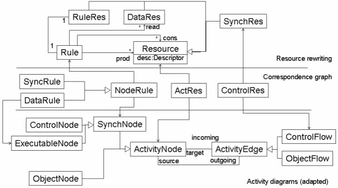
The translation process from activity diagrams to rule-based rewriting exploits Triple Graph Grammars and is based on the metamodel triple of Figure1. The source metamodel is derived from the metamodel of UML Activity Diagrams [OMG07], where we have introduced a new type, called SynchNode, to provide a missing common abstraction for ControlNode and
ExecutableNode, keeping them distinct fromObjectNode1. Note that by inheriting from
NamedElement, anActivityNodehas a name to identify it.
Figure 1: The metamodel triple relating activity diagrams and multiset rewriting.
The target metamodel provides a definition of multiset rewriting rules based on the notion of
Resourceas some distinguishable entity which can be produced or consumed in a transfor-mation. Each resource is defined by adesc attribute, coding a suitable description of it. In particular, in this context we are interested inSynchRes, used to model the flow of control, and
DataRes, used to model object flow. ARule is composed of three collections of resources:
those which areconsumed orproduced by the rule execution and those which are simplyread, i.e. they must be present, but they are not consumed. Typically, data rules do not consume their inputObjectNodes, unless they explicitly transform data. Each rule is modelled as a resource in turn, via theRuleRestype, so that rules are subject to transformation processes.
Finally, the correspondence metamodel identifies the relations between activity nodes and re-sources, between control flow edges and synchronisation rere-sources, and between synchronisation nodes and rules. In particular, anExecutableNode, besides being related to aSynchRule
through the correspondence withNodeRuleinherited fromSynchNode, will also be related to aDataRule. Such correspondence element is mapped, in the metamodel for resource rewriting, to a rule which is only concerned with the transformation of objects, but not with modification of control flow. The advancement of the control flow as the effect of the completion of the activity will be modelled, if need be, by a distinctRulerelated to theSynchRulefor that node. Not indicated in Figure1is the restriction ofObjectNodeto correspond toDataResonly.
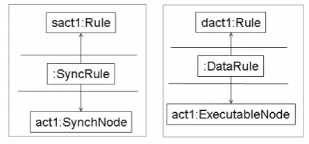
In order to define the transformation rules, we exploittriple patterns[BGL08], as a mechanism to generate triple graph operational rules, coupling syntactic and semantic roles, starting from the definition of syntactic rules. Figure 2 presents the basic patterns relating nodes to rules managing synchronisation or object transformation, while Figure 3 relates activity edges and synchronization resources. This latter pattern states that for each control flow edge in the activity diagram there is a synchronisation resource which is produced by the rule associated with the activity node which is the source of the edge, and which is consumed by the target activity node. In the following, we will use the name of the target rule as an attribute of the synchronisation resource and derive the name of the rule from the name of the corresponding activity node. Analogous patterns can be defined for object flow edges, so that an object at the end of the edge will be produced and consumed, or simply read, by the rules corresponding to the nodes related to the object.
Figure 2: The triple patterns relating activity nodes and rules.
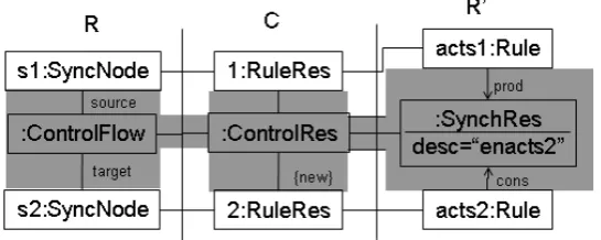
Figure 3: The triple patterns relating activity edges and synchronization resources.
keep the figures illustrating the rules compact, we adopt the following convention. The L\K component of the rule, i.e. those nodes and edges which have to be present for the match to succeed, but which are deleted by rule application, is identified by drawing light grey regions around them and tagging them with the{del}label. In an analogous way, theR\Kcomponent of the rule, denoting the elements which are created by rule application, are surrounded by dark grey regions tagged with{new}. As it is easy to see, theL=Kpart for the correspondence graph contains only theRuleResnodes, while theRpart adds theSyncResnode and its associated edges. The correspondence mappings are also generated according to the pattern.
In a similar way, the triple patterns of Figure2are used to create operational rules generating the resource rewriting rules whenever aSynchNodeis added to the diagram.
We can therefore assume that when the rule of Figure4is applied to a triple graph containing two instances ofSynchNodein its source graph, the correspondence and target graphs already contain the correspondingRuleResandRulenodes, so that these rules are enriched with the correct definition of production and consumption forSynchResnodes. An analogous effect updates the data rule associated with anExecutionNodeto reflect production or consumption of data resources according to the direction of object flow edges,
Figure 4: Construction of a triple rule from an editing rule adding a control flow.
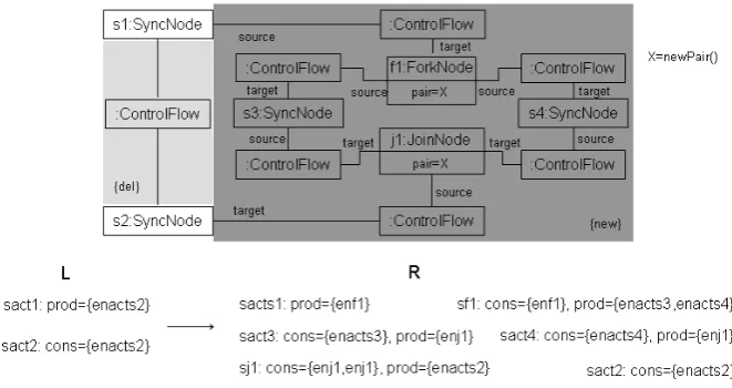
to a join node will add a new resource to theLcomponent of the rule for the join node, which will therefore require that a sufficient number of such resources are produced by its predecessors. Figure5shows the rule for inserting a fork-join pair between two existing nodes and the cor-responding updates on the rules according to the triple pattern construction. The pair is identified by an attributepair, which is an addition to the activity diagram metamodel and is computed to produce a unique new value with each pair creation. To show the effect on the set of rules, we have used a specific representation of aRuleRes, listing the multisets of enabling resources produced and consumed by each rule. The actual names in the rule description depend on the values of the description attribute. The rule descriptions in the rule resources and the actual rules are maintained consistent by the patterns.
Figure 5: Insertion of a fork-join pair and consequent modification of rules.
A similar construction holds for choice and merge nodes, where the rule for the merge node will usually be connected also to a data resource which is simply queried (i.e. read without being consumed). The abstract representation of resource rewriting rules can actually be translated to several concrete rule-based languages, as discussed in Section6.
The relation between synchronization and data transformation rules can be established fol-lowing the construction presented in [BMWY08], to relate control and data flows on spatial structures, and based on the composition of pushouts as shown in Figure6. Note that, while in [BMWY08] the construction was performed on typed attributed graph rules, we use here triple graph rules, so that eachL,K, orRcomponent in Figure6is actually a triple graph.
L 4 4 K l o
o r //
* * R 4 4 L1 K1 l1 o
o r1 //
R1
L2 K2 44
l2
o
o r2 // **
R2 L0 K0 44
l
o
o r //
R0
In particular, the intersection will result from the identification of the ExecutableNodes involved both in the control and the data flow specification. As all other nodes and edges types are different for control and data flows, the pushout will simply result by the union of all other components of the rules and of their associations with the identified nodes.
5
Patterns of transformation
The transformation of control policies in workflows can redefine sequentialization or paralleliza-tion of activities for which there is no specific order required by causal (data) dependency. Hence, these modifications should not affect the definition of the data transformation part of the activi-ties, but only the enabling mechanism.
From this point of view, it could be useful to redefine the synchronization enactment rules in an incremental way, as the transformation of the activity diagram takes place. In particular, one could thus maintain a continuous connection between the specification of the workflow and its enactment mechanism. We do not address here the problem of dynamic change – occurring when modifications are performed on workflow regions which are processing workflow instances – which can be dealt with with standard methods [EKR95].
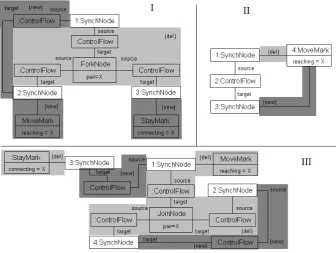
In particular, we consider the two basic adaptation patterns for control flows, i.e. sequential-ization of parallel activities and parallelsequential-ization of sequential activities, under the assumption that forks and joins are paired and correctly nested. To this end, we supplement the metamodel for activity diagrams with a pair of marker node types, calledMoveMarkandStayMark. The first is used to follow a chain of activity nodes descending from the fork node for which we want to sequentialize activities. The second marks the beginning of the second chain. Figure7shows the rules in the transformation unit for sequentializing activities included in afork-joinpair.
In particular, ruleIstarts the transformation by marking the nodes immediately below the fork node: one node is assumed to start the chain of activities, while the other will start a sequence of activities to be performed after the first one. This rule removes the fork node and the control flows associated with it and creates aControlFlowto the node marked with aMovingMarkfrom the node which preceded the fork node. The marking nodes have an attribute which identifies the fork node from which we have started. RuleIIsimply moves the marking down the chain. This rule is equipped with a negative application condition (not shown here for simplicity), which prevents the propagation of the marking if node 1 is thejoin node paired with the originating fork node. RuleII is therefore performed as long as possible until this join node is reached, at which moment RuleIIIis executed. This rule eliminates the join node and its associated control flows, relates the terminal node for the chain which will have to end the sequence with the node which descended from the join node, attaches the terminal node of the first sequence with the initial node (marked withStayMark) of the second sequence, and removes the markings.
Figure 7: The three rules for sequentialization of activities.
modified so as to start new sequentialization processes if nestedfork-joinregions are present. In this case the quest resumes for a fork from the node which is now starting the sequence.
The opposite process of parallelization can be specified through the rule of Figure8. In this case a pattern of 4 nodes in sequence has to be found (this is guaranteed by the presence of the initial and final node and the requirement that at least two activities must be performed for them to be parallelized). The rule removes all the existing control flows and inserts afork-join pair within which the two intermediate activities can now be performed concurrently. Again, the process can be iterated, and a negative application condition can be used to check that no causal dependency exists between the two activities. Similar to the case before, the operational triple rules can be derived from the patterns to ensure the incremental update of the enactment rules.
6
From abstract to concrete syntax
Figure 8: The rule for parallelization of activities.
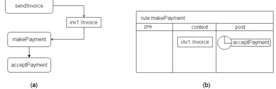
a condition compartment and an assignment compartment, where values of the attributes in the right-hand side can be evaluated. One can note that this representation is equivalent to a graph rewriting rule for typed attributed discrete graphs, in which no edges exist between entity nodes.
Figure 9: A fragment of an activity diagram (a) and a visual rule derived from it (b).
This visual representation is equivalent to the WIPPOG rule given by:
CONTEXT: invoice(id=”inv1”)
PRODUCES: synchronize(desc=”acceptPayment”)
Note that this rule is specialized to fire only when the specific invoice with name inv1 has been generated, hence the execution of a workflow coded through WIPPOG rules of this type can exploit indexing of rules according to the required resources.
7
Conclusions
In this paper, we have presented an approach to this problem, based on a simplified model of activity diagrams, suitable for the expression of non-iterative workflows, where activity nodes correspond to rules in a resource production-consumption setting.
The approach allows the separate specification of control and data flows, which results in different types of rules, which can then be integrated exploiting pushouts. The correspondence between nodes and rules, or between flows and enabling resources, is modelled through triple graph grammars, thus allowing an incremental construction and maintenance of the rules, as the diagram is edited or transformed. Although we have used patterns to generate operational rules with source in the activity graph and target in the resource rewriting metamodel, the approach could be used in a bidirectional way, so that modifications in the abstract representation of rules could be reflected to the activity diagrams. Also, the possibility of seeing rules as resources allows the execution of transformations via reflection.
While we have focused only on control and data flow, several dimensions of activity diagrams could also be explored under the resource perspective. For example, distribution could be mod-elled through the use of distribution resources associated with partition nodes, so that rules are constrained to occur only at some locations or be executed by some organizational roles. Loops could be modelled associating data resources, either already defined or suitably created, with loop variables. Alternatively, transformation units, here exploited only to perform adaptation tasks, could be extended to model some complex activities.
Acknowledgements: Partially funded by Ministry of Research, Project ”CHAT”.
Bibliography
[AB02] W. van der Aalst, T. Basten. Inheritance of Workflows: an approach to tackling problems related to change.TCS270, 2002.
[AH01] W. van der Aalst, K. van Hee.Workflow Management: Models, Methods, and Sys-tems. MIT Press, 2001.
[AHKB03] W. M. P. van der Aalst, A. H. M. ter Hofstede, B. Kiepuszewski, A. P. Barros. Workflow Patterns.Distributed and Parallel Databases14(1):5–51, 2003.
[AM00a] A. Agostini, G. D. Michelis. Improving flexibility of workflow management sys-tems. InProc. BPM 2000. LNCS 1806. Springer, 2000.
[AM00b] A. Agostini, G. D. Michelis. A light workflow management system using simple process models.Int. J. Collab. Comp.9(3-4), 2000.
[AP91] J.-M. Andreoli, R. Pareschi. Linear Ojects: Logical Processes with Built-in Inheri-tance.New Generation Computing.9(3/4):445–474, 1991.
[BDD+04] P. Bottoni, M. De Marsico, P. Di Tommaso, S. Levialdi, D. Ventriglia. Definition of visual processes in a language for expressing transitions.JVLC 15(3):211–242, 2004.
[BGL08] P. Bottoni, E. Guerra, J. de Lara. Enforced generative patterns for the specification of the syntax and semantics of visual languages.JVLC19(4):429–455, 2008.
[BMWY08] P. Bottoni, N. N. Mirenkov, Y. Watanobe, R. Yoshioka. Composing control flow and formula rules for computing on grids. InProc. GT-VMT 2008. ECEASST 10. 2008.
[Dt01] M. Dumas, A. ter Hofstede. UML Activity Diagrams as a Workflow Specification Language. InProc. UML’01. LNCS 2185, pp. 76–90. 2001.
[EKR95] C. Ellis, K. Keddara, G. Rozenberg. Dynamic Change Within Workflow Systems. In Proc. COOCS’95. ACM Press, 1995.
[EW03] R. Eshuis, R. Wieringa. Comparing Petri Net and Activity Diagram Variants for Workflow Modelling - A Quest for Reactive Petri Nets. InPetri Net Technology for Communication-Based Systems. LNCS 2472, pp. 321–351. 2003.
[Gir87] J.-Y. Girard. Linear Logic.TCS50:1–102, 1987.
[KLN+05] E.-J. Ko, S.-Y. Lee, H.-M. Noh, C.-J. Yoo, O.-B. Chang. Workflow Modeling Based on Extended Activity Diagram Using ASM Semantics. InProc. ICCSA 2005. LNCS 3482, pp. 945–953. 2005.
[KtB00] P. Kiepusziewski, A. ter Hofstede, C. Bussler. On Structured Workflow Modeling. InProc. CAiSE 2000. LNCS 1789, pp. 431–445. Springer, 2000.
[MM90] J. Meseguer, U. Montanari. Petri nets are monoids.Information and Computation 88(2):105–155, 1990.
[OMG07] OMG. Unified Modeling Language: Superstructure. OMG, 2.1.1 edition, Feb 2007.
[RHEA05] N. Russell, A. H. M. ter Hofstede, D. Edmond, W. M. P. van der Aalst. Workflow Data Patterns: Identification, Representation and Tool Support. InProc. ER 2005. LNCS 3716, pp. 353–368. 2005.
[RvtE05] N. Russell, W. van der Aalst, A. ter Hofstede, D. Edmond. Workflow Resource Patterns: Identification, Representation and Tool Support. In Proc. CAiSE 2005. LNCS 3520, pp. 216–232. 2005.
[Sch94] A. Sch¨urr. Specification of Graph Translators with Triple Graph Grammars. InWG. LNCS 903, pp. 151–163. Springer, 1994.