Installation Man u al
ePump™ Variable
Speed Pump
ePump Controller
H031 1300 Rev B 2 3 4PRESS PRESET OR MENU 12:00AM PUMP IS OFF
WARNING
FOR YOUR SAFETY - This product must be installed and serviced by a contractor who is licensed and qualified in pool equipment by the jurisdiction in which the product will be installed where such state or local requirements exist. In the event no such state or local requirement exists, the maintainer must be a professional with sufficient experience in pool equipment installation and maintenance so that all of the instructions in this manual can be followed exactly. Before installing this product, read and follow all warning notices and instructions that accompany this product. Failure to follow warning notices and instructions may result in property damage, personal injury, or death. Improper installation and/or operation will void the warranty.
Improper installation and/or operation can create unwanted electrical hazard which can cause serious injury, property damage, or death.
ePump™ Variable Speed Pump Controller Installation Manual
Table of Contents
Section 1. Important Safety Instructions ... 4
1.1 Safety Instructions ... 4
1.2 Pool Pump Suction Entrapment Prevention Guidelines ... 7
Section 2. Installation of the ePump Controller ... 9
2.1 Introduction ... 9
2.2 The Controller Panel ... 9
2.3 The Controller Components ... 9
2.4 Installation of the Backplate onto an Electrical Box ... 9
2.5 Installation of the Backplate on a Flat Wall ... 10
2.6 Connection to the Jandy ePump Variable Speed Pump ... 10
2.7 Jandy ePump Variable Speed Pump Switch Settings ... 10
2.8 Connection to Remote Contacts ... 11
2.9 Remote Operation ... 11
2.10 Remote Closure 4 Behavior ... 11
Section 3. User Operation ... 12
3.1 OFF Mode ... 12
3.2 RUN Mode ... 12
3.3 Manual Start and Stop ... 12
3.4 Pump Speed Setting ... 12
3.5 Timeclock Setup and Operation... 13
Section 4. Service Setup Options ... 14
4.1 Entering Service Setup ... 14
4.2 Minimum and Maximum Pump Speeds ... 14
4.3 Load Defaults ... 14
4.4 Last Fault ... 14
4.5 Priming Speed and Duration ... 15
4.6 eStar Speed ... 15
4.7 Pump Freeze Protect Operation ... 15
4.8 Selecting Pump Type ... 16
4.9 Display Power Usage ... 16
Section 5. User Set Up Options ... 16
5.1 Setting Time-of-Day ... 16
5.2 Labeling Presets ... 17
5.3 General Labels ... 17
5.4 Custom Labels ... 17
5.5 Display Light Control ... 17
5.6 Language Selection ... 18
5.7 Run Duration (Presets 3 and 4 Only) ... 18
5.8 Scale ... 18
Section 6. Menu Flow Chart ... 19
DATE OF INSTALLATION INSTALLER INFORMATION
INITIAL PRESSURE GAUGE READING (WITH CLEAN FILTER)
PUMP MODEL HORSEPOWER
FILTER MODEL SERIAL NUMBER
CONTROLLER MODEL SERIAL NUMBER
NOTES:
Section 1.
Important Safety Instructions
READ AND FOLLOW ALL INSTRUCTIONS
LIRE LA NOTICE TECHNIQUE.
1.1 Safety
Instructions
All electrical work must be performed by a licensed electrician and conform to all national, state, and local codes. When installing and using this electrical equipment, basic safety precautions should always be followed, including the following:
WARNING
Prolonged immersion in hot water may induce hyperthermia. Hyperthermia occurs when the internal temperature of the body reaches a level several degrees above the normal body temperature of 98.6°F (37°C). The symptoms of hyperthermia include dizziness, fainting, drowsiness, lethargy, and an increase in the internal temperature of the body. The effects of hyperthermia include: 1) unawareness of impending danger; 2) failure to perceive heat; 3) failure to recognize the need to exit spa; 4) physical inability to exit spa; 5) fetal damage in pregnant women; 6) unconsciousness resulting in a danger of drowning.
DANGER
To reduce the risk of injury, do not remove the suction fittings of your spa or hot tub. Never operate a spa or hot tub if the suction fittings are broken or missing. Never replace a suction fitting with one rated less than the flow rate marked on the equipment assembly.
WARNING
To Reduce the Risk of Injury
-a) The water in a spa should never exceed 104°F (40°C). Water temperatures between 100°F (38°C) and 104°F (40°C) are considered safe for a healthy adult. Lower water temperatures are recommended for young children and when spa use exceeds 10 minutes.
b) Since excessive water temperatures have a high potential for causing fetal damage during the early months of pregnancy, pregnant or possibly pregnant women should limit spa water temperatures to 100°F (38°C).
c) Before entering a spa or hot tub, the user should measure the water temperature with an accurate thermometer since the tolerance of water temperature-regulating devices varies.
d) The use of alcohol, drugs, or medication before or during spa or hot tub use may lead to unconsciousness with the possibility of drowning.
e) Obese persons and persons with a history of heart disease, low or high blood pressure, circulatory system problems, or diabetes should consult a physician before using a spa.
f) Persons using medication should consult a physician before using a spa or hot tub since some medication may induce drowsiness while other medication may affect heart rate, blood pressure, and circulation.
WARNING
To reduce the risk of injury, do not permit children to use this product.
WARNING
RISK OF SUCTION ENTRAPMENT HAZARD, WHICH, IF NOT AVOIDED, CAN RESULT IN SERIOUS INJURY OR DEATH. Do not block pump suction, as this can cause severe injury or death. Do not use this pump for wading pools, shallow pools, or spas containing bottom drains, unless the pump is connected to at least two (2) functioning suction outlets. Drain covers must be certifi ed to the latest published edition of ANSI/ASME A112.19.8.
WARNING
To reduce the risk of property damage or injury, do not attempt to change the backwash (multiport, slide, or full fl ow) valve position with the pump running.
WARNING
Due to the potential risk of fi re, electric shock, or injuries to persons, JandyPumps must be installed in accordance with the National Electrical Code (NEC), all local electrical and safety codes, and the Occupational Safety and Health Act (OSHA). Copies of the NEC may be ordered from the National Fire Protection Association, 470 Atlantic Ave., Boston, MA 02210, or from your local government inspection agency.
WARNING
Incorrectly installed equipment may fail, causing severe injury or property damage.
WARNING
• Do not connect system to an unregulated city water system or other external source of pressurized water producing pressures greater than 35 PSI.
• Trapped air in the system can cause the fi lter lid to be blown off, which can result in death, serious personal injury, or property damage. Be sure all air is out of the system before operating.
CAUTION
Do not start pump dry! Running the pump dry for any length of time will cause severe damage and will void the warranty.
WARNING
To minimize risk of severe injury or death, the fi lter and/or pump should not be subjected to the piping system pressurization test.
Local codes may require the pool piping system to be subjected to a pressure test. These requirements are generally not intended to apply to the pool equipment, such as fi lters or pumps.
Jandypool equipment is pressure tested at the factory.
If, however, the WARNING cannot be followed and pressure testing of the piping system must include the fi lter and/or pump, BE SURE TO COMPLY WITH THE FOLLOWING SAFETY INSTRUCTIONS: • Check all clamps, bolts, lids, lock rings, and system accessories to ensure they are properly installed and secured before testing.
• RELEASE ALL AIR in the system before testing. • Water pressure for test must NOT EXCEED 35 PSI.
• Water temperature for test must NOT EXCEED 100°F (38°C).
• Limit test to 24 hours. After test, visually check system to be sure it is ready for operation.
Notice: These parameters apply to Jandy equipment only. For non-Jandy equipment, consult the equipment manufacturer.
SAVE THESE INSTRUCTIONS
WARNING
People with infectious diseases should not use a spa or hot tub.
To avoid injury, exercise care when entering or exiting the spa or hot tub.
Do not use drugs or alcohol before or during the use of a spa or hot tub to avoid unconsciousness and possible drowning. Pregnant or possibly pregnant women should consult a physician before using a spa or hot tub.
Water temperature in excess of 100°F (38°C) may be injurious to your health.
Before entering a spa or hot tub measure the water temperature with an accurate thermometer. Do not use a spa or hot tub immediately following strenuous exercise.
Prolonged immersion in a spa or hot tub may be injurious to your health.
Do not permit any electric appliance (such as a light, telephone, radio, or television) within five 5 feet (1.5m) of a spa or hot tub. The use of alcohol, drugs or medication can greatly increase the risk of fatal hyperthermia in hot tubs and spas.
Water temperature in excess of 100°F (38°C) may be hazardous to your health.
AVERTISSEMENT
Les personnes atteintes de maladies infectieuses ne devraient pas utiliser une cuve de relaxation. Pour éviter des blessures, user de prudence en entrant dans une cuve de relaxation et en sortant.
Pour éviter l’évanouissement et la noyade éventuelle, ne prendre ni drougue ni alcool avant d’utiliser une cuve de relaxation ni quand on s’y trouve.
Les femmes enceintes, que leur grossesse soit confi rmée ou non, devraient consulter un médecin avant d’utiliser une cuve de relaxation.
Il peut être dangereux pour la santé de se plonger dans de l’eau à plus de 38°C (100°F).
Avant d’utiliser une cuve de relaxation mesurer la témperature de l’eau à l’aide d’un thermomètre précis. Ne pas utiliser une cuve de relaxation immédiatement après un exercice fatigant.
L’utilisation prolongée d’une cuve de relaxation peut être dangereuse pur la santé.
Ne pas placer d'appareil électrique (luminaire, téléphone, radio, téléviseur, etc) à moins de 1.5m de cette cuve de relaxation. La consommation d’alcool ou de drogue augmente considérablement les risques d’hyperthermie mortelle dans une cuve de relaxation.
Il peut etrê dangereux pour la santé de se plonger dans de l’eau à plus de 38°C (100°F).
Attention installer: Install to provide drainage of compartment for electrical components. WARNING
To avoid injury ensure that you use this control system to control only packaged pool/spa heaters which have built-in operatbuilt-ing and high limit controls to limit water temperature for pool/spa applications. This device should not be relied upon as a safety limit control.
1.2
Pool Pump Suction Entrapment Prevention Guidelines
WARNING
Pump suction is hazardous and can trap and drown or disembowel bathers. Do not use or operate swimming pools, spas, or hot tubs if a suction outlet cover is missing, broken, or loose.
The following guidelines provide information for pump installation that minimizes risk of injury to users of pools, spas, and hot tubs:
Entrapment Protection - The pump suction system must provide protection against the hazards of suction entrapment.
Suction Outlet Covers - All suction outlets must have correctly installed, screw-fastened covers in place. All suction outlet (drain) covers must be maintained. Drain covers must be listed/certifi ed to the latest published edition of ANSI/ASME A112.19.8. They must be replaced if cracked, broken, or missing.
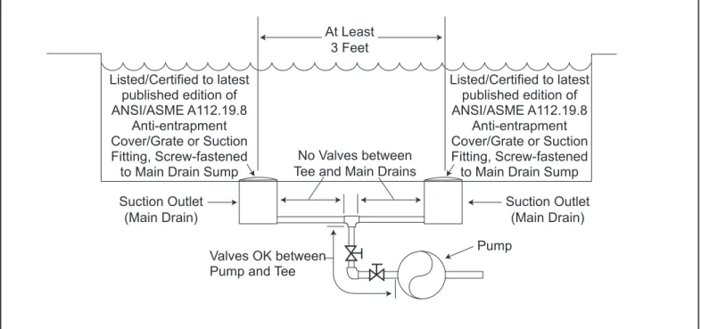
Number of Suction Outlets Per Pump - Provide at least two (2) hydraulically-balanced main drains, with covers, as suction outlets for each circulating pump suction line. The centers of the main drains (suction outlets) on any one (1) suction line must be at least three (3) feet apart, center to center. See Figure 1.
The system must be built to include at least two (2) suction outlets (drains) connected to the pump whenever the pump is running. However, if two (2) main drains run into a single suction line, the single suction line may be equipped with a valve that will shut off both main drains from the pump. The system shall be constructed such that it shall not allow for separate or independent shutoff or isolation of each drain. See Figure 1.
More than one (1) pump can be connected to a single suction line as long as the requirements above are met.
Water Velocity - The maximum water velocity through the suction fi tting or cover for any suction outlet must be 1.5 feet per second, unless the outlet complies with the latest published edition of ANSI/ASME A112.19.8, the standard for Suction Fittings For Use in Swimming and Wading Pools, Spas, Hot Tubs,
and Whirlpool Bathtub Applications. In any case, do not exceed the suction fi tting’s maximum designed
fl ow rate.
If 100% of the pump’s fl ow comes from the main drain system, the maximum water velocity in the pump suction hydraulic system must be six (6) feet per second or less, even if one (1) main drain (suction outlet) is completely blocked. The fl ow through the remaining main drain(s) must comply with the latest published edition of ANSI/ASME A112.19.8, the standard for Suction Fittings For Use in Swimming and
Wading Pools, Spas, Hot Tubs, and Whirlpool Bathtub Applications.
Testing and Certifi cation - Suction outlet covers must have been tested by a nationally recognized testing laboratory and found to comply with the latest published edition of ANSI/ASME A112.19.8, the standard for Suction Fittings For Use in Swimming and Wading Pools, Spas, Hot Tubs, and Whirlpool
Bathtub Applications.
Fittings - Fittings restrict fl ow; for best effi ciency use fewest possible fi ttings (but at least two (2) suction outlets).
Avoid fi ttings that could cause an air trap.
Pool cleaner suction fi ttings must conform to applicable International Association of Plumbing and Mechanical Offi cials (IAPMO) standards.
WARNING
SUCTION HAZARD. Can cause serious injury or death. Do not use this pump for wading pools, shallow pools, or spas containing bottom drains, unless pump is connected to at least two (2) functioning suction outlets.
At Least 3 Feet Suction Outlet (Main Drain) Suction Outlet (Main Drain) No Valves between
Tee and Main Drains
Listed/Certified to latest published edition of ANSI/ASME A112.19.8 Anti-entrapment Cover/Grate or Suction Fitting, Screw-fastened
to Main Drain Sump Listed/Certified to latest published edition of ANSI/ASME A112.19.8 Anti-entrapment Cover/Grate or Suction Fitting, Screw-fastened
to Main Drain Sump
Valves OK between Pump and Tee
Pump
ePump™ Variable Speed Pump Controller Installation Manual
Section 2. Installation of the ePump
Controller
2.1 Introduction
This document provides general instructions to install the controller for use with the Jandy ePump variable speed pump. The controller can be mounted to an electrical gang box (single, double, or triple) or to a flat wall.
The instructions have been written with safety as the priority, and must be followed exactly. Read through the instructions completely before starting the procedure.
Please note, the ePump Controller can not be used in conjunction with a Jandy PDA or OneTouch™ Controller.
2.2
The Controller Panel
The controller panel provides both timed and manual speed controls for the Jandy ePump Variable Speed Pump. Four
speed presets are directly available on the panel, while four
(4) additional presets may be accessed via the MENU key.
The up and down keys are used to adjust the pump speed. The speed is saved as it is adjusted. No further action is required to save the new speed setting after adjustment. The selected speed can be saved and assigned to one of the speed buttons.
As shown in Figure 1, preset speed "
" is assigned tothe "eStar" feature. Hence, it is intended to be assigned an energy-efficient filtration speed, as determined by the installer.
2.3
The Controller Components
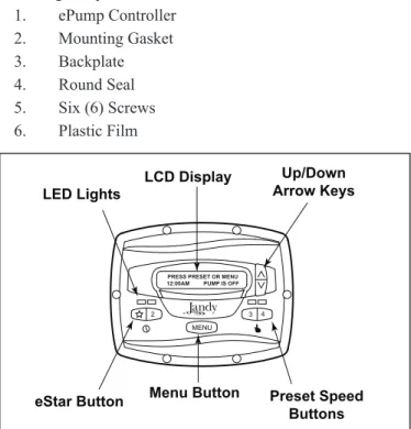
The ePump controller assembly (See Figure 3) contains the following components: 1. ePump Controller 2. Mounting Gasket 3. Backplate 4. Round Seal 5. Six (6) Screws 6. Plastic Film
Figure 2. Jandy ePumpVariable Speed Pump Controller Panel LCD Display Preset Speed Buttons Menu Button LED Lights Up/Down Arrow Keys 2 3 4
PRESS PRESET OR MENU 12:00AM PUMP IS OFF
MENU
eStar Button
Figure 3. Controller Components
Additional materials are required for the installation of the controller and must be supplied by the installer:
1. A cable to connect the pump to the remotely mounted controller, minimum size of 22 AWG (Jandy part number 4278). This cable will need to have four (4) conductors and be able to handle 24V control signals. This cable should be rated for the particular installation (for example: outdoor, UV resistant, direct burial, etc.) and should conform to all applicable codes and regulations. (A suitable cable is included in the JEP Series ePump water pumps.)
2. A minimum of two (2) fasteners to mount the controller back plate to a wall or electrical box. The fasteners should be suitable for the surface where the controller is to be remotely mounted.
3. A high-voltagedisconnect switch, as required by the
National Electric Code (NEC), within line of sight of the pump.
2.4
Installation of the Backplate onto an
Electrical Box
CAUTION
Do not expose the user interface to direct sunlight. Too much direct sunlight will darken the LCD screen, and it will no longer be readable.
1. Turn off the pump at the control panel.
2. Turn off all electrical power to the pump at the main junction box or at the circuit breaker providing electrical power to the pump.
WARNING
ELECTRICAL SHOCK HAZARD
Turn off all switches and the main breaker in the ePump electrical circuit before starting the procedure. Failure to comply may cause a shock hazard resulting in severe personal injury or death.
3. Drill out the plastic film covering the backplate screw holes. See Figure 3.
Screws (6) Controller Front Gasket Backplate Round Seal Plastic Film Screws
(not supplied with kit)
4. Secure the backplate to the box using the screws that came with the electrical box.
5. Drill out a ½" hole and insert the round seal supplied with the kit. A remote cable will run through the middle hole of the backplate and into the electrical box.
2.5
Installation of the Backplate on a Flat
Wall
CAUTION
Do not expose the user interface to direct sunlight. Too much direct sunlight will darken the LCD screen, and it will no longer be readable.
1. Turn off the pump at the control panel.
2. Turn off all electrical power to the pump at the main junction box or at the circuit breaker providing electrical power to the pump.
WARNING
ELECTRICAL SHOCK HAZARD
Turn off all switches and the main breaker in the ePump electrical circuit before starting the procedure. Failure to comply may cause a shock hazard resulting in severe personal injury or death.
3. A minimum of two (2) fasteners (installer supplied) are required when installing to a flat wall to hold the controller securely.
4. The backplate has ten (10) mounting holes to choose from. Only drill out the plastic film from the holes to be used. See Figure 3.
5. Mark the hole locations on the wall and use the fastener to secure the backplate to the wall.
6. At the bottom of the backplate, cut the two (2) tabs out with an appropriate tool, such as a carton cutter or an exacto knife, and route the cable through the open channel.
2.6
Connection to the Jandy ePump
Variable Speed Pump
The following steps provide the procedure for installing the controller to a Jandy ePump variable speed pump.
1. Turn off all switches and the main breaker that
supplies power to the pump.
WARNING
ELECTRICAL SHOCK HAZARD
Turn off all switches and the main breaker in the pump electrical circuit before starting the procedure. Failure to comply may cause a shock hazard resulting in severe personal injury or death.
2. Remove the cover of the pump junction box.
3. Feed the RS-485 cable into the fi tting.
NOTE The controller uses a four-wire RS-485 interface to communicate with the ePump.
4. Unplug the RS-485 connector from the pump.
5. Attach the four (4) wires in the RS-485 cable to the
RS-485 connector. Make sure the colors match the positions on the connector. See Figure 3.
6. Connect the RS-485 connector back into the pump.
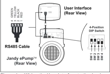
7. Set the DIP switch settings for the pump controller
with the 1 and 2 in the ON position and 3 and 4 in the OFF position. See Figure 4.
8. Turn on all switches and the main breaker feeding
power to the pump.
9. Verify the operation of the controller. If the
controller displays FAULT PUMP NOT
CONNECTED, re-check the wiring and the DIP switch address setting on the pump.
Jandy ePump (Rear View) RS485 4 3 2 1 REMOTE CONTROL 5 4 3 2 1 User Interface (Rear View) RS485 Cable 2 BLACK 3 YELLOW 1 RED 4 GREEN 4-Position DIP Switch SW 1 SW 2 SW 3 SW 4
Figure 4. Wiring the User Interface to the Jandy ePump Variable Speed Pump
2.7
Jandy ePump Variable Speed Pump
Switch Settings
For the ePump, the 4-position dip switch is located at the rear of the pump, as shown in Figure 3.
This dip switch serves two functions, it determines what type of control will be used with the pump and it selects the pump address. The SW 1 (switch 1) and SW 2 are turned ON if the pump is to be controlled by a stand alone controller or
OFF if the pump is to be controlled by the AquaLink® RS or
AquaLink® PDA. SW 1 SW 2 CONTROL OFF OFF AquaLink RS AquaLinkPDA ON OFF OFF ON ON ON Stand Alone
The SW 3 and SW 4 are turned ON/OFF to select the Pump address. SW 3 SW 4 PUMP No. OFF OFF 1 ON OFF 2 OFF ON 3 ON ON 4
ePump™ Variable Speed Pump Controller Installation Manual
2 3 4
MENU
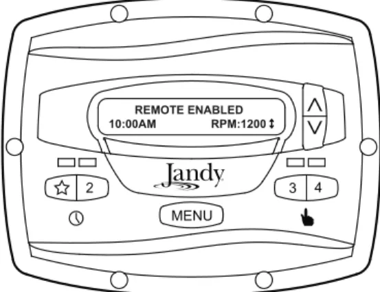
REMOTE ENABLED
10:00AM RPM:1200
The controller will remain in this state until the contact is opened. When more than one (1) contact closure occurs, the highest speed will take priority.
2.10 Remote Closure 4 Behavior
The behavior of speed "4" differs from manual operation when operated via a remote contact closure. As during manual operation, the turn-on time of remote closure 4 is immediate, and occurs at the same time as contact closure (For example, see Section 2.8). The turn-off time, however, is delayed by 30 minutes.
In other words, when remote closure 4 is de-activated, the ePump will continue to run for 30 minutes, after which time the controller will turn off the ePump. The delay may be manually interrupted by pressing any preset key.
2.10.1 Remote Closure 4 Application -
Booster Pump Support
The behavior of remote closure 4 may be used to allow an external timeclock fitted with a 20-minute “fireman’s switch” (e.g., Intermatic P/N 156T4042A) to properly control the ePump in conjunction with a booster pump.
Connection for Booster Pump Support:
1. Turn off all switches and the main breaker that
supplies power to the ePump.
WARNING
ELECTRICAL SHOCK HAZARD
Turn off all switches and the main breaker in the ePump electrical circuit before starting the procedure. Failure to comply may cause a shock hazard resulting in severe personal injury or death.
2. Install the normally-closed fi reman’s switch to the
timeclock assembly. (See timeclock manufacturer’s instructions for details.)
3. Connect the main timeclock contacts to the booster
pump power input per the booster pump installation manual.
4. Connect one side of the fi reman’s switch to the
ePump Controller at J3 REMOTE CONTROL, COMMON.
5. Connect the other side of the fi reman’s switch to
the ePump controller at J3 REMOTE CONTROL, INPUT 4.
Figure 5. Connection to Remote Contacts
RS485 4 3 2 1 RED BLACK YELLOW GREEN REMOTE CONTROL 5 4 3 2 1 INPUT 2 INPUT 3 INPUT 4 COMMON INPUT 1 J3 Remote Contact Closure input common
2.8
Connection to Remote Contacts
The controller allows speeds "
" through "4" to operate viaremote contact closures (switch or relay). Speed "4" operates differently than the other three. See Section 2.10, Remote Closure 4 Behavior.
1. Turn off all switches and the main breaker that
supplies power to the ePump.
WARNING
ELECTRICAL SHOCK HAZARD
Turn off all switches and the main breaker in the ePump electrical circuit before starting the procedure. Failure to comply may cause a shock hazard resulting in severe personal injury or death.
2. Connect one side of the remote contact closure to the
COMMON terminal on J3 REMOTE CONTROL connector of the controller. See Figure 5.
3. Connect the other side of the remote contact closure
to INPUT 1, INPUT 2, INPUT 3, or INPUT 4 terminal on J3 REMOTE CONTROL connector of the controller, depending on which speed is to be controlled.
4. Turn on all switches and the main breaker feeding
power to the ePump.
5. Verify the operation of the contact closures. If
the correct speed is activated when the closure is activated, the ePump starts, and the message
REMOTE ENABLED appears on the controller display.
NOTE When starting the pump via a remote closure, the pump will first run at the priming speed for the priming duration, as set by the installer.
2.9 Remote
Operation
Speeds activated via remote closures always override speeds that have been activated manually or via an internal timer program. When the pump is activated via a remote
closure, the keypad is disabled and the message REMOTE
6. Set the timeclock to the desired on/off times.
7. Turn on all switches and the main breaker feeding
power to the ePump.
8 If the installation is working properly, the fi reman’s
switch will open 20 minutes before the booster pump shuts down, the ePump will continue to run for 30 minutes, and the ePump Controller will display
PUMP WILL REMAIN ON FOR XX:XX, where
XX:XX is the time remaining until ePump shutdown.
Section 3. User Operation
3.1 OFF
Mode
When the pump is off (not running), the controller displays
PRESS PRESET OR MENU/00:00 PUMP IS OFF, where 00:00 is the time-of-day clock.
2 3 4
PRESS PRESET OR MENU 12:00AM PUMP IS OFF
MENU
3.2 RUN
Mode
When the pump is running (not off), the controller displays
N:LABEL/00:00 RPM:XXXX, where n:label is the number and label of the selected preset, 00:00 is the time-of-day clock, and xxxx is the pump speed.
2:PRESET 2
10:00AM RPM: 1200 ↕
2 3 4
MENU
3.3
Manual Start and Stop
Up to eight (8) programmed speeds may be started from the controller. Manual operation of speeds "eStar" through "4" differs from manual operation of speeds "5" through "8".
NOTE When starting the pump, the pump will first run at the priming speed for the priming duration, as set by the installer.
3.3.1
Speeds eStar through 4
To start the pump manually running at speeds "eStar" through "4", press button "
" through "4" corresponding to the desired speed. The associated LED will light red and thecontroller enters the RUN mode.
2 3 4
MENU
2:PRESET 2 10:00AM RPM: 1200 ↕
To stop the pump, press the button again. The associated LED will extinguish and the pump and controller will return to the
OFF mode.
3.3.2
Speeds 5 through 8
To start the pump manually at speeds "5" through "8",
press the MENU button. The controller displays SELECT
PRESET/N:LABEL, where n:label is the number and label of the last selected preset "5" through "8".
Using the arrow keys, select the desired preset to activate,
and then press MENU to enter RUN mode, starting the pump
running at the selected speed.
2 3 4
SELECT PRESET 5:PRESET 5
MENU
To stop the pump, press MENU. To exit without starting the
pump, press any button "
" through "4".3.4
Pump Speed Setting
With the exception of preset "
", the pump speed for eachpreset may be adjusted while the pump is running in that
preset mode. Preset "
" is reserved for the eStar function,and its speed is set by the installer.
To adjust the pump speed, the controller must be in the RUN
mode. While in RUN mode, the controller displays the pump
speed. Adjust the speed by pressing the up or down arrow keys. The speed is saved by the controller and will remain until changed again.
NOTE Pump speed is adjustable only within a certain range. The minimum and maximum limits of the range are set by the installer.
ePump™ Variable Speed Pump Controller Installation Manual NOTE When used with a solar system, set speed to at least
3000 RPM and potentially up to 3450 RPM, based on the pump's head required to push the water up a minimum of 12-15 feet.
2 3 4
MENU 2:PRESET 2 10:00AM RPM: 1400
3.5
Timeclock Setup and Operation
The controller allows the user to create timed pump programs
on pump speeds (presets) "
" and "2". The two timersoperate independently of each other, and may overlap in time if desired.
3.5.1 Timeclock
Setup
Start the desired speed, "
" or "2". Press MENU. The controller enters the Timeclock setup mode. Using the arrowkeys, select ON TIME and press MENU. Set the desired
pump turn-on time using the arrow keys and press MENU.
The time is stored. Select OFF TIME using the arrow keys
and press MENU. Set the desired pump turn-off time using
the arrow keys and press MENU. The time is stored.
2 3 4
MENU 2:PRESET 2 TIMECLOCK ON TIME
Using the arrow keys, select TIMECLOCK. Select ENABLE
using the arrow keys. The program is now enabled to run. Press the preset button ("
" or "2") to return to the RUNmode. 2 3 4 MENU 2:PRESET 2 TIMECLOCK ENABLE
3.5.2 Timeclock
Operation
When the pump is stopped, the associated green LED will illuminate, indicating a timeclock program is enabled for that speed.
If two (2) timed programs overlap, the program with the faster speed will take priority and run to completion. If the earlier-starting program is still active, it will resume operation.
The program off times never change, i.e., they are not ‘pushed-out’ in time when programs overlap. Timeclock programs may be prematurely stopped by stopping the pump manually from the keypad. This override is active until the program start time is reached again, at which time the timed program will start the pump as programmed.
If the pump is started manually at a speed that has been programmed with a timer, the pump will be stopped by the timeclock at the programmed off time.
NOTE When starting the pump via a timed program, the pump will first run at the priming speed for the priming duration, as set by the installer. If a program overlap occurs, the pump will immediately start at the program speed without priming first.
3.5.3
Manually Overriding a Timer
Program
Timeclock programs may be prematurely stopped by pressing the active preset key. This override is active until the program start time is reached again, i.e., for 24 hours, at which time the timed program will start the pump as programmed.
2 3 4
PRESS PRESET OR MENU 12:00AM PUMP IS OFF
MENU
3.5.4
Timer Overriding a Manual On
If the pump is started manually at a speed that has een programmed with a timer, the pump will be stopped by the timeclock at the programmed off time. A clock icon appears on the display when the timer has assumed control of the off time.
Section 4. Service Setup Options
The service setup menu allows the installer to set various operating parameters, view fault history, and restore factory defaults.
Parameters that may be modified and set in the service setup menu include:
• Priming speed and duration.
• Minimum and maximum pump speeds. • "" eStar speed.
• Pump Freeze Protect operation.
4.1
Entering Service Setup
NOTE The ePump controller must be in the OFF mode (all LED's lights must be off) before entering the user setup mode. While in setup mode the controller will return back to the OFF mode after one (1) minute since the last key press.
To enter the service setup menu, press and hold MENU, then
press and hold the "
" and preset "4" keys. Hold all three (3) keys down for five (5) seconds. To exit, press any preset button.2 3 4
MENU PRESS PRESET OR MENU 12:00AM PUMP IS OFF
4.2
Minimum and Maximum Pump
Speeds
These speeds are considered global settings across the entire controller, and create the range of allowable speed that may be sent to the ePump.
To set the minimum speed, from the service setup menu,
select SET MIN LIMIT using the arrow keys. Press MENU.
Using the arrow keys, set the minimum speed to the desired
value. Press MENU to accept and store.
2 3 4
SET MIN LIMIT RPM: 600
MENU
To set the maximum speed, from the service setup menu,
select SET MAX LIMIT using the arrow keys. Press MENU.
Using the arrow keys, set the maximum speed to the desired
value. Press MENU to accept and store.
2 3 4
SET MAX LIMIT RPM: 3450
MENU
4.3 Load
Defaults
To restore factory default settings to the controller, from
the service setup menu, select LOAD DEFAULTS. Press
MENU. Using the arrow keys, select YES. Press MENU to
restore factory default settings.
2 3 4 LOAD DEFAULTS YES MENU Default Speeds eStar 1750 RPM Preset 2 - 8 2750 RPM Priming Speed 2750 RPM Other Defaults
Freeze Protect Duration 30 min
Priming Duration 1 min
4.4 Last
Fault
This feature shows on the top display line, the most recent unique fault message and on the bottom display line, the second-to-last unique fault message. If there is no entry for a fault, the display will show “*---*” on the corresponding line. To select last fault, from the service setup
menu select LAST FAULT. Press MENU.
NOTE The fault messages are stored in non-volatile memory, and remain even with no power. To clear the fault history, press either arrow key.
ePump™ Variable Speed Pump Controller Installation Manual
2 3 4
SELECT SERVICE SETUP LAST FAULT
MENU
4.5
Priming Speed and Duration
The ePump controller will command the ePump to operate at the priming speed for the priming duration specified (except during timer program overlaps or follow-on commands where the pump is not stopped before changing speeds). From the
service setup menu, select PRIMING using the arrow keys.
Press MENU.
2 3 4
PRIMING DURATION MIN: 3
MENU
To set priming speed, select PRIMING SPEED using the
arrow keys. Press MENU. Using the arrow keys, set the
priming speed to the desired value. Press MENU to accept
and store.
2 3 4
PRIMING SPEED RPM: 3450
MENU
To set priming duration, select PRIMING DURATION using
the arrow keys. Press MENU. Using the arrow keys, set the
priming speed to the desired value in minutes from one (1) to
five (5) minutes. Press MENU to accept and store.
2 3 4
PRIMING DURATION MIN: 3
MENU
4.6 eStar
Speed
The "
" speed is intended to be used as an energy-efficientsetting that can be easily called-up by activating the eStar preset speed from the keypad or remote closure. After this speed has been determined by the installer, the eStar preset may be set as follows: From the service setup menu, select
SET ESTAR SPEED. Press MENU. Using the arrow keys,
set the speed to the desired value. Press MENU to accept and
store.
2 3 4
1:eSTAR RPM:1250
MENU
4.7
Pump Freeze Protect Operation
When enabled to do so, the ePump controller monitors the temperature inside the pump and will activate the ePump at the eStar speed when the temperature approaches freezing. The run duration of the pump freeze protect operation is adjustable from 30 minutes to 8 hours, or may be disabled completely.
To set the pump freeze protect operation, from the service
setup menu select PUMP FREEZE PROTECT. Press
MENU. Using the arrow keys, set the duration to the desired
value. To disable pump freeze protect, set the duration to
0:00. Press MENU to accept and store.
2 3 4
PUMP FREEZE PROTECT 1:05
Important Information on Freeze Protection
Freeze protection is intended to protect equipment and plumbing for short periods of freezing only. It does this by activating the filtration pump and circulating the water to prevent freeze inside equipment or plumbing. Freeze protection does not guarantee that equipment will not be damaged by extended periods of freezing temperatures or power outages. In these conditions, the pool and spa should be shut down completely (e.g. drained of water and closed for the winter) until warmer weather exists.
The pump freeze protect run time may be interrupted by pressing a preset key, as follows:
Pressing the key "
" once overrides the pump freeze protectrun time, pressing it twice turns off the pump. Pressing other preset keys will override the pump freeze protect run time and activate the selected preset speed.
2 3 4
MENU PUMP FREEZE PROTECT 1: FILTRATION
4.8
Selecting Pump Type
The ePump controller may be used to operate various types of pumps. It is important to select the correct pump type at this menu item to ensure proper controller operation.
From the setup menu, select PUMP TYPE. Press the MENU
button to display the currently selected pump type. Using the arrow keys, choose the pump type that matches the type of the installed pump. Refer to the pump manual for information regarding the pump type.
2 3 4
MENU CONFIG UTILISATEUR TYPE DE POMPE
4.9
Display Power Usage
The ePump controller can alternately display the ePump power usage while the pump is in operation and the controller is in Run Mode.
To enable the power display feature, from the service setup
menu select DISPLAY POWER USAGE. Press MENU to
select. Using the arrow keys, select YES. Press MENU to
accept and store.
To disable the power display feature, from the service setup
menu select DISPLAY POWER USAGE. Press MENU
to select. Using the arrow keys, select NO. Press MENU to
accept and store.
2 3 4
MENU CONFIG UTILISATEUR CONSOMMATION ÉLECT
Section 5. User Set Up Options
NOTE The ePump controller must be in the OFF mode before entering the user setup mode. While in setup mode the controller will return back to the OFF mode after one (1) minute since the last key press.
When in setup mode, preset keys "
" through "4" are usedas ‘escape’ or exit keys while navigating the setup menu.
To enter the setup mode, press and hold the MENU button
for five (5) seconds. The controller displays SELECT USER
SETUP. Using the arrow keys, select the desired setup item to change.
5.1 Setting
Time-of-Day
From the Setup menu, select SET TIME. Press the MENU
button to display the currently-set time. Using the arrow keys,
adjust to the desired time. Press MENU to save your setting.
2 3 4
MENU SELECT USER SETUP SET TIME
ePump™ Variable Speed Pump Controller Installation Manual
5.2 Labeling
Presets
The ePump controller comes from the factory with pre-programmed labels or names for the preset speeds. The labels may be changed as desired to suit your particular installation. Two (2) types of labels are provided by the controller:
• General Labels - selected from a list • Custom Labels - created by the user
From the setup menu, select LABEL PRESET. Press the
MENU button to display the currently selected Preset. Using
the arrow keys, choose the preset to be changed. Press MENU
to select. The controller displays SELECT LABEL TYPE.
Select GENERAL or CUSTOM as desired using the arrow
keys.
2 3 4
MENU SELECT USER SETUP LABEL PRESET
5.3 General
Labels
Using the arrow keys, select a general label from the list to
assign to the Preset. Press MENU to assign the label to the
Preset. 2 3 4 MENU LABEL PRESET FILTRATION
5.4 Custom
Labels
In the custom label mode, the controller displays a flashing cursor at the character position to be changed. Using the
arrow keys, change the character as desired. Press MENU to
accept the change and advance to the next character position. Press any preset key "
" through "4" to return to the previous cursor position.2 3 4
MENU LABEL PRESET 1:PRESET 1
Continue this procedure until the end of the label is reached.
The new label is saved when MENU is pressed at the last
character position.
5.5
Display Light Control
The controller’s display is equipped with a backlight to aid viewing in low light conditions.
From the setup menu, select DISPLAY LIGHT. Press
MENU. Using the arrow keys, select the desired operating
mode for the display backlight:
LIGHT OFF: Turn off display backlight.
LIGHT ON: Turn on display backlight.
2 MIN TIMEOUT: Turn on display backlight, with automatic turn-off after two (2) minutes since the last key press.
2 3 4
MENU SELECT USER SETUP DISPLAY LIGHT
5.6 Language
Selection
From the setup menu, select LANGUAGE using the arrow
keys. Press MENU. Using the arrow keys, select the desired
language. Press MENU to save the selection.
2 3 4
MENU SELECT USER SETUP LANGUAGE
5.7
Run Duration (Presets 3 and 4 Only)
Presets "3" and "4" may be programmed to run for a specified duration after being manually started. This run duration is programmable from 30 minutes to eight (8) hours, in increments of 30 minutes. A setting of 0:00 disables the run duration feature, allowing the preset to run indefinitely.
From the setup menu, select RUN DURATION. Press
MENU. Using the arrow keys, select the preset to be
programmed. Press MENU. Set the desired run duration for
the preset using the arrow keys. Press MENU to accept.
2 3 4
MENU SELECT USER SETUP RUN DURATION
5.8 Scale
NOTE This selection may not appear as part of the setup menu depending on the type of pump connected.
If the connected pump is capable of flow control, the SCALE
menu may be used to select flow or speed operation.
From the setup menu, select SCALE. Press the MENU
button to display the currently selected scale. Using the arrow keys, choose the scale that corresponds to the type of control desired.
A setting of RPM allows control by speed, while a setting of
GPM allows control by flow. Press MENU to select the scale.
2 3 4
MENU CONFIG UTILISATEUR ECHELLE
ePump™ Variable Speed Pump Controller Installation Manual
Section 6. Menu Flow Chart
[OFF] USER SETUP (Note 6) ON TIME SET TO [10:00AM] DISPLAY LIGHT
[ 2 MIN TIME OUT ] (Note 8) LIGHT OFF LIGHT ON PRESET X (Note 5) SET TO [2750] RPM R: MIN TO MAX I: 10RPM (Note 2) SET TIME TIMECLOCK [DISABLE] ENABLE SET TO [12:00AM] R: 12:00AM TO 11:59PM I: 1 MIN LANGUAGE SELECTION (Note 7) [ENGLISH] SPANISH FRENCH LABEL PRESET SELECT PRESET SET TO [5] R: 5 TO 8 I: 1 PRESET 3 OR 4 (Note 1,4) SET TO [2750] RPM R: MIN TO MAX I: 10RPM (Note 2) SET TO [12:00AM] R: 12:00AM TO 11:59PM SET TO [12:00AM] R: 12:00AM TO 11:59PM NOTES
Default parameters are shown in [ ]. “R” stands for Range.
“I” stands for Increment.
1. Accessed directly by front panel button. 2. Occurs at Run Screen.
3. Timeclock features accessed via MENU button while Preset is running.
4. MENU button has no effect when running. 5. Accessed via MENU button when pump is stopped. 6. Press and hold MENU button for five (5) seconds to enter. 7. Is not affected when “LOAD DEFAULTS” is executed. 8. Key that is pressed to wake up display is also acted upon. 9. Press and hold MENU, eStar, and 4 simultaneously for five (5) seconds to enter.
10. Setting not saved in non-volatile memory; reset to “NO” after execution.
11. Only appears when connected to pump capable of flow control. USE USER SETUP SET TO [“PRESET n”] R: ALL CHARS SELECT LABEL TYPE GENERAL CUSTOM LABEL LIST PRESET 2 (Note 1,3) SET TO [2750]RPM R: MIN TO MAX I: 10RPM (Note 2,3) RUN DURATION SELECT PRESET SET TO [0:00] R: 30 MIN TO 8 HRS I: 30 MIN eSTAR
(Note 1,3) SET TO [4:00PM]OFF TIME
SERVICE SETUP (Note 9) LOAD DEFAULTS (Note 10) [NO] YES LAST FAULT [LAST FAULT] [2ND TO LAST]
SET MIN LIMIT
SET TO [600] R: 600 TO MAX LIM
I: 10
SET MAX LIMIT
SET TO [3450] R: MIN LIM TO 3450
I: 10 SET ESTARSPEED
SET TO [1750]RPM R: MIN TO MAX I: 10RPM SET TO [0:30] R: 0 MIN TO 8 HRS I: 30 MIN PUMP TYPE [ePUMP 60Hz] VSP AC PRIMING [SPEED] DURATION SET TO [2750] R: MIN LIM TO SET TO [1] R: 1 TO 5 MIN DISPLAY POWER USAGE [NO] YES TIMECLOCK [DISABLE] ENABLE SET TO [12:00AM] R: 12:00AM TO 11:59PM SET TO [12:00AM] R: 12:00AM TO 11:59PM OFF TIME SET TO [4:00PM] ON TIME SET TO [10:00AM] FREEZE PROTECT SERVICE SETUP SCALE (Note 11) [RPM] GPM ePUMP 50Hz
H031 6000 Condor Drive • Moorpark, CA USA 93021 • 800.822.7933 • Fax 877.327.1403 © 2010 Zodiac Pool Systems, Inc. 1004