An Experimental Approach to Examine a Multi-Channel Multi-Hop Wireless
Backbone Network
Yuzo Taenaka1, Masaki Tagawa1,2and Kazuya Tsukamoto3
E-mail: [email protected]
1Information Technology Center, The University of Tokyo, Japan
2Graduate School of Information Science, Nara Institute of Science and Technology, Japan 3Department of Computer Science and Electronics, Kyushu Institute of Technology, Japan
Keywords: traffic management, channel utilization, experiment, multiple channels, OpenFlow, wireless backbone net-work, multi-hop netnet-work, wireless LAN
Received:July 16, 2015
This paper presents an experimental deployment of a multi-channel multi-hop wireless backbone network (WBN) with an OpenFlow-based traffic management method. Specifically, a set of APs, each of which uses a single but different channel, is connected by Ethernet and thus constructs a Virtual AP (VAP), thereby achieving a WBN with multiple channels. To flexibly control traffic flows transmitted over a multi-channel multi-hop WBN, we propose a simple traffic management method based on the OpenFlow control. In the performance evaluation, we first conduct a preliminary experiment as a lab scale and then deploy a 6-hop WBN enabling to provide the Internet access service in a conference (from proof-of-concept to a practical environment). Since the control messages are inherently transmitted with the introduction of OpenFlow, the way of isolation between control plane and data plane will become a critical issue to actually deploy the proposed system for the Internet service. We additionally employ a wireless control network for the conference experiment. The experimental results show that the proposed WBN can increase the network capacity in accordance with the number of channels, thereby providing significant throughput performance for various applications.
Povzetek: Predstavljena je eksperimentalna analiza veˇc-kanalnega veˇc-skokovnega brezžiˇcnega ogrodja za mreže.
1
Introduction
The use of various mobile devices such as smartphones and tablets is rapidly widespread and is becoming increasingly essential to our daily life. A large amount of data is ex-changed for various purposes such as video communication and streaming, and thus it is expected to increase by about 11 times between 2013 and 2018 [1].
Since this growth of the mobile traffic is faster than the increase of the network capacity in the advanced cellular technology such as LTE/4G, cellular carriers are rapidly de-ploying public WLAN access points (APs) to offload the mobile traffic. However, each WLAN coverage is rela-tively small so that APs tend to be densely placed within specific locations such as shops and a part of public space, thereby suffering radio interference of APs due to highly overlapped coverage. From these considerations, the way of extending WLAN coverage is essential.
To achieve this, a wireless mesh network (WMN) that extends WLAN coverage attracts much attention. A WMN mainly consists of two sorts of APs: gateway AP (called Internet gateway (IGW)) providing the Internet reachabil-ity to other APs and other APs constructing a multi-hop wireless backbone network (WBN) to reach the IGW (i.e., the Internet). Since a WMN can extend its coverage due
to the ease of WBN extension, WMN has been already de-ployed in relative wide area (e.g., a shopping mall and a city).
However, the existing WMN always suffers a limited network capacity due to the nature of multi-hop transmis-sion on multi-hop network. To offload the mobile traffic, the network capacity of a WBN has to be increased so that it can accommodate the amount of the increasing traf-fic reliably. In particular, since the mobile traftraf-fic basically passes through the IGW (i.e., from/to the Internet), the net-work capacity on a single route toward the IGW should be increased.
schemes. Also, since an existing AP hardware only has a few wireless interfaces (IFs) (two IFs generally), the num-ber of channels that the AP can use simultaneously is less than the number of IFs that the AP equips with even when many channels (more than the number of IFs) are vacant.
To physically increase the network capacity, IEEE 802.11n/ac have a function of the channel bonding [7, 8]. In the channel bonding, consecutive channels have to be vacant. However, it is quite difficult to monopolize the use of all vacant channels because there are multiple but not consecutive vacant channels scattered in the 2.4 GHz and 5 GHz bands in a real environment. In preliminary experi-ments, we observed that there are many vacant channels in the 5 GHz band, which means that the available resources cannot be used effectively. Thus, the flexible way of inte-grating the scattered channels becomes crucial.
From the distinctive points, two problems should be ad-dressed to increase the network capacity of a WBN. One is the limitation on the number of channels that APs can use simultaneously. Another is under-utilization of the channels in use. To address these problems, we first pro-pose an efficient framework, which is potentially capable of handling the unlimited number of channels in paral-lel. A multi-channel management framework by exploiting OpenFlow is also presented. To the best of our knowledge, there is no literature that not only focuses on these prob-lems but also applies the OpenFlow based approach to the WBN. We then implement these frameworks in a real AP hardware/software and experimentally deploy two sorts of WBNs (a lab scale proof-of-concept and a 6-hop WBN pro-viding the Internet service). In the experiment, we exam-ine the feasibility of our WBN implementation/deployment and also evaluate the effectiveness of increasing the net-work capacity.
2
Related work
Many studies attempted to increase the network capacity of a WMN by using multiple channels [2–6]. The major-ity of them focuses on routing protocols, channel assign-ments, and MAC protocols [3]. Most studies propose a multi-channel routing protocol [4, 9], which jointly works with channel assignment [5]. The use of multiple chan-nels potentially enables to simultaneously transmit packets, thereby being effective to increase the network capacity. However, the number of channels APs can simultaneously use is limited because a practical AP hardware equips with generally two radios and three radios in maximum as far as we know. Therefore, many studies assume that each AP has only two IFs [5]. Since multiple vacant channels more than two are often available, the number of channels each AP simultaneously uses should be flexibly increased in ac-cordance with the number of vacant channels.
The routing studies basically switch channels (routes) to avoid radio interference. However, these studies cannot si-multaneously use multiple links (channels) between two
AP2-1
AP2-2
AP2-3
VAP2 AP1-1
AP1-2
AP1-3
VAP1 Ch. B
Ch. C Ch. A
AP3-1
AP3-2
AP3-3
VAP3
AP4-1
AP4-2
AP4-3
VAP4
Secondary
AP
Primary
AP
handle multiple APs as an AP, virtually
Multi-hop wireless backbone network Can switch channels by changing APs
Ch. B
Ch. C Ch. A
Ch. B
Ch. C Ch. A
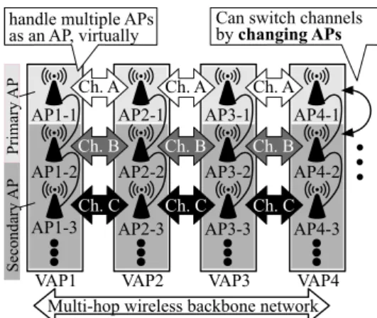
Figure 1: Virtual AP based multi-channel WBN.
neighboring APs because the routing table contains only a single link to reach a neighbor AP. That is, the network capacity between two APs cannot be increased, thereby be-ing a bottleneck. To potentially increase the capacity, pack-ets have to be transmitted through different channels even if all packets are destined to the same destination address. Thus, a traffic management framework that can use multi-ple channels in parallel is essential.
The studies focusing on MAC protocol try to sched-ule frame transmissions for collision avoidance between nearby APs [6, 10]. Reference [11] proposes a new MAC protocol transmitting packets on multiple channels based on channel hopping on a single radio (practical hardware equipment). Although it can handle multiple channels, the switching delay in the order of several milliseconds [12] is inherently necessary at every channel switching. It cannot effectively use multiple channels due to the delay and the time-allocated manner. Then, the multiple channels have to be used simultaneously to completely exploit their avail-able resources.
From the viewpoint of OpenFlow, there are few studies employing OpenFlow in WMN [13, 14]. They use Open-Flow functions to provide user mobility in WMN. They mention about the utilization of multiple channels but the structure of WMN is the same with the existing WMN, which does not use multiple channels in parallel. That is, the channel utilization of multiple channel on each hop is not considered.
3
Multi-channel WBN enabling to
increase network capacity
3.1
Handling multiple channels
mul-tiple wireless links of different channels with neighboring VAPs simultaneously, switching forwarding path of a flow is the same meaning with switching channels of the flow.
As shown in Figure 1, one AP in each VAP is treated as a primary AP (e.g., AP1-1) and the others are secondary APs. Both the primary and secondary APs construct WBNs on respective channels, while only the primary APs provide the Internet access to client terminals. From this architec-ture, the number of channels used in parallel can be flexibly increased by adding APs for VAP. Note that, to easily iden-tify each VAP, a VAP is indicated with a number, called VAPID, (=X) such like VAP-X. In the same way, the sub-APs is denoted as AP-X-Y, whereYis a sequence number of APs in a VAP, called APID.
3.2
Channel utilization of WBN
In WBN, we assume that a routing protocol identifies a route toward IGW (e.g., VAP4→VAP3→VAP2→VAP1 in Figure 1)1 and thus all traffic are forwarded along with the identified route. To use multiple channels on the route, we propose a traffic management framework based on soft-ware defined network (i.e., OpenFlow) technology, which enables us to flexibly select a path (channel) for eachflow
at each hop. A flow is defined based on various identifica-tions from layer 1 to layer 4. In this study, we use a 4-tuple (source/destination IP address and port number) as the flow identification.
OpenFlow consists of one OpenFlow Controller (OFC) and some OpenFlow Switches (OFSs). The OFC estab-lishes a TCP connection with each of OFSs for control mes-sage exchange. Then, the OFC determines control rules for each flow (called flow entries) and registers them to OFSs. An OFS (an AP in this study) actually manages packets of each flow by following the registered flow entries stored in the local database (called flow table). Thus, the OFC essen-tially controls all flow by registering flow entries to OFSs.
A flow entry consists of a flow identification and a cor-responding action. In the study, flow entries are registered (a) when an OFS initially connects with the OFC, and (b) when the OFC receives apacket_in, which is sent by an OFS whenever the OFS receives an unknown packet (i.e., the packet does not match any flow entries in the flow ta-ble). A set of flow entries registered at (a) is fixed rule and is called asbase entry. Also, the process that the OFC cre-ates/registers a flow entry to an OFS is called asflow_mod.
3.3
Traffic management framework
We propose a traffic management framework based on OpenFlow technology. Since a single OFC can collabora-tively work with all OFSs and can totally manage all flows through the connected OFSs, the OFC has a potential to dy-namically manage flows in response to the variations of the traffic condition in whole WBN. Thus, the channel utiliza-tion can be optimized by exploiting the OpenFlow based
1Routing is beyond the scope of this paper.
VAP1 VAP2 VAP3 VAP4
#1 #2 #3
OpenFlow Controller
packet_in
Flow #1 → Ch. A Flow #2 → Ch. B Flow #3 → Ch. A
Ch. A
Ch. B flow
entry
select a different channel in arrival order
AP1-1
Base entry prev. hop → next hop next hop → prev. hop if dst = my client
conduct multi-hop transmission deliver to the client
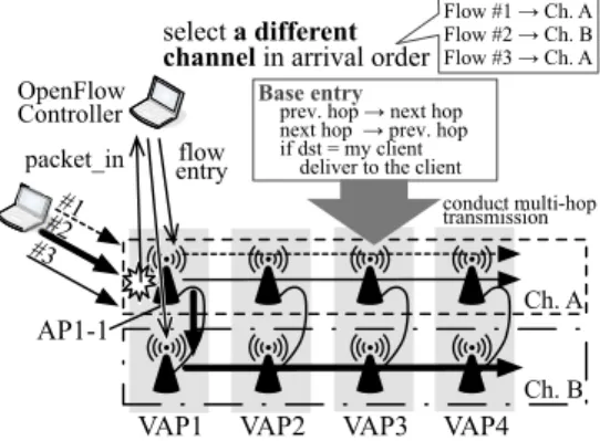
Figure 2: An example of traffic management on multi-channel WBN.
WBN. To evaluate the performance of the OpenFlow based WBN, we here propose a simple channel utilization method that can multiplex a conventional (single-channel) multi-hop transmission as an example method.
In this method, the OFC allocates a channel for each flow in order of the arrival ofpacket_inand the selected chan-nel is persistently used for multi-hop transmission in the WBN. Figure 2 shows the mechanism of the channel uti-lization method. The OFC initially registers flow entries (base entry) to all OFSs when establishing a control TCP connection with each OFS. The base entry consists of rules that make all APs forward flows from the previous hop to the next hop and from the next hop to the previous hop. Note that, if the destination of the flow is a client device connecting to its VAP, the AP directly delivers the flow to the destination. Thus, all APs have the base entry conduct-ing multi-hop transmission in advance.
When a client terminal starts a new communication (flow), a first packet arrives at one of APs (e.g., AP 1-1 in Figure 2) and the AP sends a packet_in to the OFC. The OFC determines the identification of the flow based on the combination of source/destination pairs of<IP ad-dress, port number>, selects a channel persistently used on all hops for the flow, and then registers flow entries, which transmits packets of the flow via the selected channel. In the next hop, the flow is transmitted by the base entry in ac-cordance with the transmission direction. In this way, the combination of the base entry and packet_in driven flow entry achieves the utilization of multiple channels.
3.4
Overhead introduced by OpenFlow
The delay due to packet_in/flow_mod message exchange and the management traffic coming from this message ex-change inherently become overhead. When an AP receiv-ing a new flow (a first packet of new flow), the AP sends a packet_in to the OFC unless a flow entry matching the flow is registered in the AP. The OFC then selects a chan-nel for the flow and registers new flow entry (flow_mod) indicating the selected channel to transmit the flow. Af-ter that, the AP starts to forward the flow based on the in-formed flow entry. Therefore, the delay for registration of flow entry, which highly depends on round trip time (RTT) between the AP and the OFC, is necessary only when re-ceiving a first packet of each flow (i.e., only once for each flow). Moreover, the processing delay for channel selec-tion is also necessary, but it limits to a quite short period. So, the communication interruption period almost becomes RTT between the AP and the OFC.
On the other hand, OpenFlow does not require extra de-lay to process packets except a first packet of each flow. The OFS process works as a Linux kernel module (ker-nel process) in each AP and handles packets instead of the TCP/IP stack on the Linux kernel. That is, the OFS pro-cess refers to the flow table to forward packets. This kind of process is almost same with the process of the TCP/IP stack, which refers the forwarding information base to for-ward packets. The paper [13] actually examined the de-lay by using a userland OFS software and showed that the throughput performance does not depend on the number of flow entries if simple rules (match on port numbers only) are used. Since our method also use only simple rules for all flow entries, the introduction of OpenFlow does not im-pact on the performance in our study.
From the viewpoint of the amount of management traf-fic, the amount of traffic by packet_in/flow_mod is nec-essary. A packet_in message consists of the OpenFlow header (18 bytes) and the entire frame that triggers a new packet_in, while a flow_mod contains some flow entries. That is, the amount of each packet_in depends on the data frame size but the amount of a flow_mod is always same size (150 bytes per frame) in our method. Actually, since we employ UDP with 1500-byte packets (=1514-byte frame), the size of packet_in becomes 1598 bytes (= Eth-ernet/IP/TCP header (66 bytes) + OpenFlow header (18 bytes) + entire frame (1514 bytes)). Also, since our method triggers packet_in once when receiving a new flow, the total amount of extra traffic will be proportional to the number of the arrivals in new flows and thus the extra management traffic can be limited to a considerable little value.
4
Lab scale proof-of-concept
To evaluate the proposed multi-channel multi-hop WBN, we first construct a lab scale WBN and demonstrate the feasibility of the proposed WBN.
VAP2 VAP1
0.7m
0.7m
VAP3 VAP4
100ch
112ch
124ch
136ch
PC1 PC2
Control network (Ethernet)
OFC
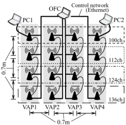
Figure 3: AP placement in the lab scale testbed.
4.1
Facilities and environment
We prepare Buffalo WZR-HP-AG300H as AP hardware. We also install OpenWrt [16] (linux-based OS) with Open vSwitch [17] to all APs. Open vSwitch is a kernel-land OFS software that controls packet transmissions in APs. For the OFC software, we employ Trema [18].
Figure 3 shows the AP placement in the lab scale testbed, which is a 3-hop WBN. Each AP of a VAP is placed to 0.7 m apart from each other and the distance between two neighboring VAPs is 0.7 m. To enable OpenFlow based control, all OFSs (APs) directly connect to an OFC by us-ing dedicated wired network to establish a control connec-tion with the OFC.
In the wireless settings, IEEE802.11a is used to con-struct the WBN and also four channels (100, 112, 124, and 136 channels) are selectively assigned for the exper-iment. Note that there is no radio interference on these channels with any other nearby WLANs. To generate traf-fic, we prepare two PCs, PC1 and PC2. These PCs are connected to AP1-1 and AP4-1 by Ethernet, respectively, because we here focus on the multi-hop data transmission over the WBN.
4.2
Performance measurement in case of
UDP traffic
We investigate the maximum network capacity in accor-dance with the number of channels used in parallel. Note that we define the network capacity as the total throughput at the end host. To keep same traffic rate independent to the network condition, PC1 generates UDP traffic of con-stant bitrate by using iperf. Specifically, PC1 sends 40 UDP flows (1,500 byte packets) with fixed 1 Mbps to PC2 one by one at 5 seconds interval (totally, 40 Mbps). During the experiment, we measure the total amount of traffic received by PC2 and average the total throughput for 30 seconds af-ter 5 seconds since the last flow starts. This experiment is performed nine times.
Table 1: Total throughput in UDP (Mbps).
# of channels used in parallel 1 ch. 2 ch. 3 ch. 4ch.
Maximum 9.73 19.14 29.03 38.47 Median 9.71 19.05 28.91 38.16 Minimum 9.58 18.96 28.80 38.13
Table 2: Total throughput in TCP (Mbps).
# of channels used in parallel 1 ch. 2 ch. 3 ch. 4 ch.
Maximum 7.67 15.08 22.75 30.14 Median 7.53 15.05 22.66 30.06 Minimum 7.44 14.88 22.60 29.98
In the results, although the total data rate of UDP flows is 40 Mbps, the obtained throughput cannot reach it. Since the traffic is equally distributed in this experiment, all chan-nels on the WBN are exhaustive filled by the traffic. That is, the maximum UDP throughput means the maximum net-work capacity of the WBN. Then, we can see from the re-sults that the network capacity with a single-channel 3-hop WBN is about 10 Mbps. According to the increase of the number of channels used in parallel, the network capacity also increases. Indeed, it becomes twice in 2 channels and three times in 3 channels. Therefore, our WBN can linearly increase the maximum network capacity in response to the increase of channels.
4.3
Performance measurement in case of
TCP traffic
In the Internet access network, there are various flows in which TCP is a dominant. In this experiment, we measure the TCP performance on our WBN while increasing the number of channels used in parallel. TCP has a function that dynamically controls transmission rate depending on the network condition so that traffic congestion could be avoided. Due to the latency of congestion control, we can expect that the network capacity in case of TCP is lower than that in case of UDP. We then examine the (effective) network capacity in the realistic traffic environment.
In this experiment, PC1 performs some TCP data trans-missions. Specifically, PC1 establishes a TCP connection with PC2 and transmits data by using iperf through the con-nection. The number of this TCP flows is increased from one up to 40 one by one at every 5 seconds. As for the capacity, we average the total throughput for 30 seconds after 5 seconds since the last flow starts. This experiment is performed nine times.
Table 2 shows the summary of experimental results. As with Table 1, Table 2 shows that the total throughput is linearly increased in accordance with the number of chan-nels used in parallel. However, the obtained throughput is clearly less than the results in Table 1 due of the congestion
0 5 10 15 20 25 30 35 40
0 20 40 60 80 100 120 140 160 180 200 220
Total throughput [Mbps]
Time [s] TCP (1ch)
TCP (2ch) TCP (3ch)
TCP (4ch)
UDP (1ch) UDP (2ch) UDP (3ch) UDP (4ch)
40 flows
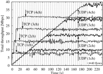
Figure 4: Time series variation on median results.
control mechanism, as stated previously.
We next compare TCP with UDP in the time series shown in Figure 4. To illustrate this figure, we select the median results in Tables 1 and 2. Since the number of UDP flows is gradually increased up to 40 flows at every 5 sec-ond, throughput also grows along with the increase of flows until the maximum network capacity, which is determined by the number of channels used in parallel. On the other hand, in TCP experiment, once at least one flow is trans-mitted on every channel, the total throughput is kept in al-most same value irrespective of the number of TCP flows (before the number of flows reaches to 40). Moreover, af-ter all flows start to be transmitted, the TCP throughput is about 2Mbps lower on each channel than that of UDP. That is, it is totally 8 Mbps lower in case of the 4-channel WBN. From these results, we can say that our WBN can poten-tially increase the network capacity in accordance with the number of channels used in parallel but the effective capac-ity is different depending on the characteristics of traffic.
5
WBN providing the Internet
access
VAP
3
VAP
1
100ch +104ch
112ch +116ch
124ch +128ch
136ch +140ch Assistant AP
VAP
2
192.168.2.0/16 192.168.3.0/16
NAT
Internet No
WLAN
2.4GHz +5GHz (built-in IFs)
(a) Internet access network.
VAP
3
VAP1
Assistant AP
Multi-hop control network OFC
10.0.
1
.0/24
VAP
2
10.0.
2
.0/24
10.0.
3
.0/24
10.0.254.0/24 10.0.254.0.1 10.0.254.0.2 10.0.254.0.3
(b) OpenFlow control network.
Figure 5: Construction of an experimental network.
5.1
Installation environment
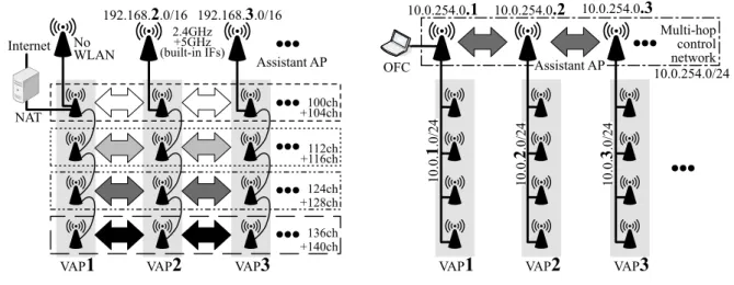
As shown in the lower part of Figure 5(a), we employ four APs for each VAP (i.e., four channels available on WBN). These four APs are connected by Ethernet of daisy chain and compose a VAP. Each AP uses the channels of 100, 112, 124, and 136 for WBN, respectively.
In the WLAN settings on all APs, IEEE802.11n is used and an adjacent channel is bonded (i.e., 40 MHz channel bonding is activated). For example, the channel 104 is bonded with the channel 100. It should be noted that our proposed WBN framework can adapt to change in the wire-less technology such as 802.11ac and its channel bonding technology. We then manage user traffic through these four links by our proposed channel utilization method described in Section 3.3. Note that we confirmed that there is no ra-dio interference on these channels with any other nearby WLANs in the hotel.
5.2
Assistant APs
We have investigated the basic performance of a lab scale WBN in Section 4. Since our focus was the way of con-structing the WBN and its performance, we simplified the experimental environment, as described in Section 4.1.
Each VAP must provide WLAN access for the Internet service. Also, to deploy our proposed WBN in a large scale network, the control traffic arising from OpenFlow should be conveyed on wireless network. Thus, we additionally prepare a Buffalo WZR-HP-AG300H equipped with a USB wireless IF (i.e., this AP has two built-in IFs and one USB IF) for each VAP, called assistant AP. The assistant AP allows us not only (1) to provide WLAN access to client terminals but also (2) to construct the control network, as shown in Figure 5.
5.2.1 Providing the WLAN access
To achieve (1), an assistant AP provides WLAN access in both 2.4 and 5 GHz bands by using two built-in IFs (Fig-ure 5(a)). These WLANs are config(Fig-ured as IEEE802.11n with 20 MHz channel width (i.e., the channel bonding is not used for client user access).
These two IFs and one Ethernet port of the assistant AP are bridged in layer 2 based on the Linux bridge module in OpenWrt and the Ethernet port is connected to the pri-mary AP (i.e., AP-X-1) by Ethernet. The primary AP then acts as a DHCP server and dynamically allocates an IP ad-dress for each client terminals in accordance with VAPID. For example, when a client terminal associates with the as-sistant AP of VAP2 on the 2.4GHz or 5GHz bands, an IP address in 192.168.2.0/16 is assigned for the client terminal by AP2-1. From this structure, the primary AP can handle user traffic of all client terminals associating with the assis-tant AP through the Ethernet port.
5.2.2 Control network conveying OpenFlow message
To carry the control messages between an OFC and OFSs, the IP reachability between an OFC and OFSs have to be guaranteed in advance. However, OFS’s IFs controlled by OpenFlow cannot receive/transmit any packets until the connection between the OFC and the OFS is established because the OFS does not have any flow entries at first. Thus, the OFS cannot reach the OFC through our WBN. To solve the problem, the control network must be con-structed separately from the user network (i.e., WBN). We then prepare the dedicated control network constructed by assistant APs, which are not managed by OpenFlow.
wire-23.84 m
30.56 m
1.6 m
11.36 m
43.62 m
8.68 m
V AP1
VAP2
VAP3 VAP4 VAP5
VAP6
VAP7
!" #$%%& '$$()*
'$$()+
%,-.& ,/
0 %,-.&
,/ 0
%,-.& ,/0
%,-.&
,/ 0
screen
Figure 6: Map of VAP placement in the experimental de-ployment.
VAP5
VAP6
Figure 7: Actual placement of VAP5 and VAP6.
less IF. Since the multi-hop control network is not managed by OpenFlow but a conventional IP routing based network, each OFS can communicate with the OFC in advance. It should be noted that, since this paper focuses on how to use multiple channels on a large scale WBN, the feasibility of the control network will be addressed in the future work.
5.3
AP placement
Figure 6 shows a map of a part of the conference venue with the AP placement. We place seven VAPs in two rooms (Room A and B). An example of the VAP deployment (VAP5 and VAP6) is shown in Figure 7. As seen in the figure, we adjust the location of VAP so as to have line-of-sight between two neighboring VAPs. That is, doors be-tween VAP2 and VAP3 and bebe-tween VAP3 and VAP4 are always opened.
VAP1 located in Room A is the IGW and directly
con-Table 3: Throughput for 30 seconds (Mbps).
Maximum Median Minimum 30.61 28.94 27.31
nects with the OFC. That is, user traffic and control traffic of OpenFlow must pass through VAP1. To ensure that user traffic is forwarded in multi-hop, VAP1 (i.e., the assistant AP of VAP1) does not provide the WLAN access to client terminals as shown in Figure 5(a). Instead, VAP1 (the pri-mary AP of VAP1) connects to a router, which performs NAT of 192.168.0.0/16, so that all users can access the In-ternet.
Since our proposed WBN can construct only a chain topology with static routing at this time, we design a 6-hop chain topology with a pre-defined path, which is shown by arrows in Figure 6. Thus, all user traffic is forwarded on this multi-hop WBN along with the path.
In the conference, Room A is used for a meeting and Room B is for a plenary event. Since the conference atten-dees concentrate in Room B when a plenary event is held, we place VAP6 and VAP7 around the plenary event area. As shown in Figure 7, the plenary event area is right side of Room B (in front of the screen) and thus almost atten-dees may associate with VAP6 or VAP7.
5.4
Performance measurement
We measure the network capacity by obtaining the sum of throughput of all flows on the WBN. In Section 5.4.1, we investigate the maximum network capacity when no users utilize the WBN. Section 5.4.2 evaluates the practical net-work capacity when many users simultaneously access the Internet by using various applications.
5.4.1 Maximum network capacity
We obtain the maximum performance of the WBN. In this experiment, two PCs connect to VAP1 and VAP7 by Ether-net, respectively, and UDP traffic is transmitted from VAP7 to VAP1 to obtain the maximum network capacity of a 6-hop WBN. During this experiment, there is no other traffic than the experimental UDP traffic.
In the preliminary experiment, we investigated the UDP transmission rate that meets the maximum channel capacity of a 6-hop WBN with a single channel (Figure 6). The measurement is conducted by increasing transmission rate of UDP with 1,500-byte packet by iperf. Since we find that 8 Mbps is the maximum capacity of a channel (packet loss rate is less than 1%) in advance, we here use this traffic rate to measure the network capacity of our WBN.
0 5 10 15 20 25 30 35
0 10 20 30 40 50 60
Throughput [Mbps]
Time [s] 45s
8 Mbps UDP x 4 flows
Figure 8: Time series throughput of the average result on the median result.
the table, we can see that the proposed WBN can provide around 29 Mbps of the network capacity.
Figure 8 shows the time series throughput of the median result in Table 3. In the figure, we can see that the through-put dynamically fluctuates between 25 and 30 Mbps. Also, the maximum instantaneous throughput is 33.28 Mbps at 45 seconds. From these results, we can say that the pro-posed WBN potentially has 29 Mbps of the network capac-ity.
5.4.2 Practical network capacity
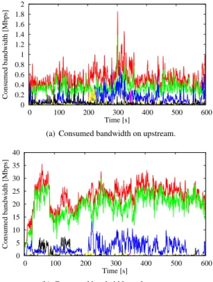
We next treat a case where clients (conference attendees) use the WBN to reach the Internet. To obtain the practi-cal network capacity, we measure the total throughput at VAP1 during a plenary event. As a measurement result, we intentionally select the period of 10 minutes during the con-ference when the largest amount of traffic is observed. Fig-ure 9 shows the actually measFig-ured traffic forwarded from/to each VAP during the 10 minutes in time series. From Fig-ures 9(a) and 9(b), we can see that the amount of the down-stream traffic is extremely larger than that of the updown-stream traffic, i.e., about 0.5 Mbps upstream traffic and about 25 Mbps downstream traffic. That is, the asymmetric nature of the Internet traffic can be seen.
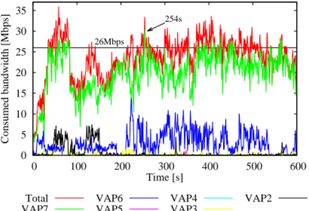
From Figure 10, we can see that almost traffic is from/to VAP6 and VAP7. When focusing on VAP7, the through-put measured at 254 seconds is 30.42 Mbps, which is the maximum instantaneous traffic during 10 minutes but a lit-tle less than that of UDP experiments (Section 5.4.1). We also show that the stable throughput on VAP7 is around 26 Mbps. Since the WBN of this experiment provides the WLAN Internet access to client terminals, TCP traffic is likely to be dominant in the Internet. As evaluated in Sec-tion 4, TCP cannot completely utilize the network capacity due to its congestion control mechanism. Therefore, the network capacity utilized by TCP becomes a little less than the results in Section 5.4.1.
From above results, the OpenFlow based WBN can aggregate the capacity of multiple channels efficiently,
0 0.2 0.4 0.6 0.8 1 1.2 1.4 1.6 1.8 2
0 100 200 300 400 500 600
Consumed bandwidth [Mbps]
Time [s]
(a) Consumed bandwidth on upstream.
0 5 10 15 20 25 30 35 40
0 100 200 300 400 500 600
Consumed bandwidth [Mbps]
Time [s]
(b) Consumed bandwidth on downstream.
Figure 9: Consumed bandwidth for 10 minutes during a plenary event.
thereby providing the Internet access with the large net-work capacity. In summary, we can conclude that the WBN can effectively extend WLAN coverage while maintaining the large network capacity.
6
Discussion
In this paper, we prepared the experimental environ-ment with no difference/variation of wireless link qual-ity and then conducted experiments to perform the proof-of-concept of the proposed architecture handling multiple channels efficiently. To apply it to the real deployment, we still have some concerns including the difference/variation on wireless condition, the difference/variation on commu-nication, reliability of control network, scalability, and de-ployment.
0 5 10 15 20 25 30 35
0 100 200 300 400 500 600
Consumed bandwidth [Mbps]
Time [s] 254s
26Mbps
Total VAP7
VAP6 VAP5
VAP4 VAP3
VAP2
Figure 10: Total bandwidth during the event.
flow) along with the change of channel condition.
To adaptably utilize channels, the OFC has to quickly obtain the difference and variation of wireless condition and then flexibly control the channel utilization. How-ever, since OpenFlow is originally designed for to-point wired network, it is not capable of treating to- point-to-multipoint wireless network, i.e., the OFC cannot ob-tain any wireless information. To overcome this, the OFC may estimate the wireless link condition based on Open-Flow technology. Actually, since the OFC is capable to collect the amount of sent/received traffic in each AP, the OFC may be aware of the difference or degradation of wire-less link quality by comparing the amount of sent traffic in an AP with the amount of the received traffic on the next hop. In this way, we also need to develop the way of obtain-ing the wireless link condition and accordobtain-ingly controllobtain-ing the channel utilization.
Since various sorts of communication are conducted in a real WMN, the channel utilization method has to han-dle them to effectively utilize multiple channels. Since the flow arrival timing, flow length, and transmission rate are various, the optimization of channel utilization is extremely difficult. That is, some channels may be saturated even if other channels are not full yet. Although the OFC selects a different channel in the order of packet_in arrival in this paper, the amount traffic loaded on each channel may also be additionally considered to utilize multiple channels.
The reliability of OFC and control network should be considered to employ OpenFlow. Since the focus of this paper is proof-of-concept, we actually have not ensured the reliability yet. For improving the OFC reliability, a sim-ple way that prepares multisim-ple OFCs in the WBN may be effective. On the other hand, to keep the control network reliable, it must have redundancy because there is a sin-gle point of failure in the current control network. Specif-ically, since a multi-hop network with a single channel is dedicated for the control network in the current WBN, the WBN causes communication failures if one of wireless links in the control network is disturbed or disconnected. To avoid it, the control network should be construct by mul-tiple channels. Since the channel resources are limited, the
control traffic may be coexistent with the data traffic in our WBN.
The scalability issue of the control network should be addressed. As described in Section 3.4, the delay of packet_in/flow_mod delay may increase in accordance with the WBN size. Moreover, the saturation of the con-trol network should be considered. A dedicated channel is used for a multi-hop control network in our WBN. On one hand, the number of clients (flows) tends to increase in ac-cordance with the WBN size (i.e., the coverage area). The control traffic may be dropped due to the saturation of con-trol network in the extensive WBN. These concerns should be further investigated.
Finally, to actually deploy the WMN based on our WBN, we have to consider the configuration and deployment way. In the current WBN, we configure all APs in advance so that all wireless connections including the control network are certainly established. For the deployment, it is neces-sary to establish the wireless connection and then detect the topology (neighboring APs). Since as we described above the OpenFlow has no functions for wireless network, we need to further develop a way to handle wireless infor-mation in the OpenFlow technology. Actually, monitor-ing beacon frames may be useful to obtain the availability of the channels and collect the information of neighboring APs.
7
Conclusion
To increase the network capacity, this paper introduces the OpenFlow based WBN and a channel utilization method. The WBN is examined in two sorts of testbed. First, we evaluate the basic characteristics of a lab scale proof-of-concept. In the testbed, since we simplified the experimen-tal environment (i.e., client nodes are connected to AP by an Ethernet cable and also the control messages of Open-Flow are conveyed through the wired network), we need to provide WLAN access to client terminals and to construct the wireless network for transmitting control messages.
To solve these problems, we employ an additional AP and then deploy the WBN in a large-scale testbed providing the Internet access to conference attendees. In the measure-ment, we can demonstrate that the WBN can bring the large amount of network capacity in 6-hops with 4 channels. From the results of two experiments, we can conclude that our WBN can extend WLAN coverage while linearly in-creasing the network capacity in accordance with the num-ber of channels used in parallel. Since this study focuses on the proof-of-concept of our WBN, we next plan to solve remaining concerns including the difference/variation on wireless condition, the difference/variation on communica-tion, reliability of control network, scalability, and deploy-ment.
References
[1] Cisco Visual Networking Index. Global Mobile Data Traffic Forecast Update, 2013–2018. http: //www.cisco.com/c/en/us/solutions/ collateral/service-provider/
visual-networking-index-vni/white_
paper_c11-520862.pdf.
[2] P. H. Pathak and R. Dutta. A Survey of Network De-sign Problems and Joint DeDe-sign Approaches in Wire-less Mesh Networks. IEEE Communications Surveys and Tutorials, 13(3):396–428, 2011.
[3] D. Benyamina, A. Hafid, and M. Gendreau. Wireless Mesh Networks Design - A Survey. IEEE Communi-cations Surveys and Tutorials, 14(2):299–310, 2012.
[4] E. Alotaibi and B. Mukherjee. Survey Paper: A Sur-vey on Routing Algorithms for Wireless Ad-Hoc and Mesh Networks. Computer Networks, 56(2):940– 965, February 2012.
[5] W. Si, S. Selvakennedy, and A. Y. Zomaya. An Overview of Channel Assignment Methods for Multi-radio Multi-channel Wireless Mesh Networks.
Journal of Parallel and Distributed Computing, 70(5):505–524, May 2010.
[6] K. S. Vijayalayan, A. Harwood, and S. Karunasek-era. Distributed Scheduling Schemes for Wireless Mesh Networks: A Survey. ACM Computing Survey, 46(1):14:1–14:34, July 2013.
[7] IEEE Std 802.11n-2009.
[8] IEEE Std 802.11ac-2013.
[9] A. Raniwala, K. Gopalan, and T. Chiueh. Central-ized Channel Assignment and Routing Algorithms for Multi-channel Wireless Mesh Networks. SIG-MOBILE Mob. Comput. Commun. Rev., 8(2):50–65, 2004.
[10] P. Kyasanur, J. So, C. Chereddi, and N. F. Vaidya. Multichannel mesh networks: challenges and proto-cols. IEEE Wireless Communications, 13(2):30–36, May 2006.
[11] J. So and N. H. Vaidya. Multi-channel Mac for Ad Hoc Networks: Handling Multi-channel Hidden Ter-minals Using a Single Transceiver. In MobiHoc, pages 222–233, 2004.
[12] A. Raniwala and T. Chiueh. Architecture and algo-rithms for an IEEE 802.11-based multi-channel wire-less mesh network. InINFOCOM, pages 2223–2234, 2005.
[13] P. Dely, A. Kassler, and N. Bayer. OpenFlow for Wireless Mesh Networks. InIEEE ICCCN, pages 1– 6, 2011.
[14] A. Detti, C. Pisa, S. Salsano, and N. Blefari-Melazzi. Wireless Mesh Software Defined Networks (wmSDN). In2nd International Workshop on Com-munity Networks and Bottom-up-Broadband, pages 89–95, 2013.
[15] M. Tagawa, Y. Wada, Y. Taenaka, and K. Tsukamoto. Network Capacity Expansion Methods based on Ef-ficient Channel Utilization for Multi-Channel Wire-less Backbone Network. Inthe 2014 International Workshop on Smart Complex Engineered Networks (SCENE), August 2014.
[16] OpenWrt.https://openwrt.org/.
[17] Open vSwitch. http://openvswitch.org/.