ROLE OF PRESSURE IN COMBATING OIL PIPELINE VANDALIZATION IN NIGERIA
Ibekwe, B. E.
Department of Electrical and Electronic Engineering, Faculty of Engineering
Enugu State University of Science and Technology (ESUT), Enugu
ABSTRACT
This paper is on the role of pressure in combating the incessant vandalism meted on our NNPC oil
pipelines the various parts of the country. The paper tries to explain the concepts of pressure in
fluid flow and proffered solutions by taking the advantage of pressure in checking and fighting the
activities of hoodlums and pipeline vandals. It also highlighted some of the immediate and remote
causes of the pipeline vandalizaiton and what federal and state government should do to curb
the activities and the consequent 'inferno' when there is fire outbreak.
KEY WORDS: NNPC oil pipelines, Pressure, Pipeline Vandals, Flow meters, Bernoulli’s Theorem.
1.0 INTRODUCTION
Oil pipeline vandalizaiton is the collaboration of criminals, disgruntled elements and people who
felt that they are marginalized, to perpetrate evil on NNPC pipelines by cutting oil pipes to suck and
cart away either crude oil, refined petrol and gas or kerosene for selfish interests and money.
In-depth studies have revealed that the following are some of the major causes of oil pipeline
vandalizaiton in Nigeria.
(i) Incessant fuel crisis and hike in price in the country.
(ii) Poor infrastructural facilities, sometimes none at all, to the oil communities, Niger Delta is
a case-in-point.
(iii) Youths un-employment and economic hardship in the country,
(iv) Greed and the quest to get rich quicker on the part of some unpatriotic Nigerians.
1.1 STATEMENT OF THE PROBLEM
It has become a custom in this country that fuel crises must occur at least once or twice
not natural, disgruntled elements among Nigerians create an artificial crisis. Hoarding and
adulteration of the motor spirit among others go on unabated in a given crises situation.
Again poor infrastructural facilities and sometimes none at all, for the oil localized communities is one
of the major root-cause of pipeline vandalizaiton. A case-in-point is Niger Delta, where there are
no good schools, hospitals and maternities, good access roads, portable water etc.
To crown it up, a lot of soil and marine devastations have occurred through oil spillages. Many
of their soil have been rendered barren and sea animals e.g. fishes have died inequalities in
their rivers. And federal government and oil companies are culpable for these anomalies.
Moreover, youth unemployment and economic hardship in Nigeria today have contributed to
more than 60% problems in oil pipeline vandalization because an "idle mind is the devil's workshop".
Therefore government should create jobs for its teeming youth population and restructure the
quality of our educational system to be more skill and practical oriented such that youths can
create jobs rather than being job seekers.
Furthermore, lack of patriotism is another root cause of these problems because "love of one's
country" has been relegated to the background. People no longer think of what they can do for
Nigeria but what Nigeria can do for them. The quest to grab a fair share of the "national
cake" is the craze everywhere and the result is milking the country to death through all these
nefarious activities and vandalism.
2.0 FLUIDS
A section of the applied mechanics concerned with statics and dynamics of liquids and gases is the
mechanics of fluid[1]. A fluid is something that can flow. Frequently, fluid mechanics is concerned with
streams of fluid instead of individual bodies or particles.
Hydraulics (from the Greek word for water) is the study of the problems of flow and storage of water
but it often applied to other liquids as in the case of hydraulic control gear usually using oil as the
operating fluid [1]. A fluid can offer no permanent resistance to any force causing change of
shape and fluids flow under their own weight and take the shape of any solid body with which they
are in control e.g. pipes etc.
Fluids are divided into liquid and gases. A liquid is difficult to compress and any given mass of it,
occupies a fixed volume irrespective of the size of the container holding it/and a free surface is
easily compressed and it expands to fill any vessel in which it is contained and it does not form a
free surface [1].
Again for a fluid, the rate of strain is proportional to the stress while deformation of solid up to the
limit of elasticity is such that strain is proportional to the applied stress. Moreover, the strain of a
solid is independent of the time of application of the force and if the elastic limit is not exceeded,
the deformation disappears when the stress is removed while a fluid continues to flow as long
as the stress is applied and does not recover its original form when the stress is removed [1].
2.1 LIQUIDS IN MOTION
There is no shear force in a fluid at rest but, when it is in motion, shear forces can be set up due
to viscosity and turbulence which oppose motion producing a "frictional" effect. Although
many problems can be solved at least partially by assuming an ideal frictionless (in viscid) fluid [2].
A fluid consists of a large number of individual particles moving in the general direction of
flow but usually not parallel to each other. The velocity of any particle is a vector quantity,
having magnitude and direction which vary from moment to moment. The path followed by a
particle is called path line. At any given instant of time, the positions of successive particles can
be joined up by a curve which is tangential to the directio n of motion of the particle at
that instant. This curve is called a streamline and is ordinarily a curve of three dimensions. If
streamlines are drawn through every point on the circumference of a small area, they form a
stream tube.
Fig. 2.1: The Streamline
2.2 TYPES OF FLOW
Two distinct types of flow occur in a flowing fluid:
(i) Turbulent flow, in which the particles of fluid move in disorderly manner
occupying different relative positions in successive cross-sections,
(ii) Viscous flow, also known as streamline or laminar flow, in which the particles of the fluid move
in an orderly manner and retain the same relative positions in successive cross-section [2].
Osborne Reynolds found that the type of flow is determined by the velocity, density, viscosity of
the fluid and of course the size of the conduit and depends on the value of the Reynolds number,
vd/ where v = velocity, = mass density and = viscosity of the fluid, while d is a typical
dimension which for a pipe is the diameter [2]. For flow in pipes, if the Reynolds number is less
than 2100 approximately, flow is always viscous while Reynolds number greater than 2100
approximately is turbulent flow.
3.0 FLOW METHODS IN PIPES/ CONDUITS (ROLE OF PRESSURE)
(i) Gravity flow: is that in which the fluid e.g. oil flow under gravity maintaining certain grades or natural topography characterized with heights and elevation. The flow here can
be turbulent especially if there are drops and cascades along the flow line e.g. drain.
The fluid in the pipe has no free surface. It will be at a pressure above or below atmospheric, and
this pressure may vary along the pipe.
(ii) Pumping stations: pumping stations are installed where the natural grades can no longer be maintained for gravitational flow to be possible and where a hilly topography is
hit. Pumps are installed in such locations to force pressure into the pipe conduits to
maintain continuity of flows. The pressure here is so forceful and powerful and the
range and coverage depends on the pumps capacity.
Most of the times the pumping stations supplement the gravitational flow effort in forcing the
flowing liquids to final destination [5].
3.1 ENERGY IN FLOWING LIQUIDS
Flowing liquids e.g. oil may possess three forms of energy [ 1 & 2].
(i) Potential energy: This is due to its elevations above datum level. If a weight w of a liquid is at a height z above datum, the potential energy is wz.
(iii) Pressure energy: When a fluid e.g. oil flows in continuous stream under pressure, it can do work. Pressure head p/w is the pressure energy per unit weight.
(iv) Kinetic energy: The kinetic energy per unit weight V2/2g is also measured as a length and therefore referred to as the velocity head.
The total energy of the liquid is the sum of these three forms of energy. Therefore, the total
energy per unit weight,
H = Z + P
/W+ V
2
/2g ……. (3.1) [2].
Where P/W = potential head
V2/2g = velocity head
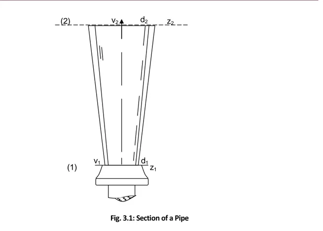
Referring to fig. 3.1, let v1, d1, and z1, be the velocity, diameter of the jet and the elevation of the nozzle
respectively and let v2, d2 and z2 be the corresponding value at the upper level. At both sections the oil is at
atmospheric pressure PA.
By Bernoulli’s theorem,
Total energy per unit weight at section 1 = total energy per unit weight at section 2.
Thus,
g
v
w
PA
z
g
v
w
PA
z
2
2
2 2 2 2 11
………. 3.2:. 2 1
2 2 2 1
2
g
z
z
v
v
…….. 3.3
or
H
Fig. 3.1: Section of a Pipe
According to Bernoulli's theorem, the total energy of each particle of a body of fluid is the same
provided that no energy enters or leaves the system at any point [2&3].
3.1.1 LOSSES OF ENERGY IN PIPELINES
A pipe is defined as a closed conduit of circular section through which the fluid flows filling the complete
cross-section. The fluid in the pipe has no free surface. It will be at a pressure above or below atmospheric
and this pressure may vary along the pipe. Losses of energy in a pipeline are due to:
(a) Shock from the disturbance of the normal flow due to bends or sudden changes of sections, and
(b) Frictional resistance to flow.
These losses are conveniently expressed as energy lost in N-m/N, that is to say as head lost in terms of
fluid in the pipe, and related to the velocity head. If v = velocity in the pipe, velocity head =
g
v
2
2
; and
head lost = K(v2/2g) where k is a constant. Losses of energy in a pipeline cannot be ignored when the
shock losses and friction loss have been determined; they are inserted in the Bernoulli’s’ equation in the
usual way, so they are far from the pipeline vandalization being considered.
3.1.2 HEAD LOST WHEN A PIPE UNDERGOES A SUDDEN INCREASE IN DIAMETER OR CHANGES IN
SECTION
The loss of head when a pipe undergoes a sudden increase in diameter or enlargement can be
(1) v1 d1z1
demonstrated as shown below:
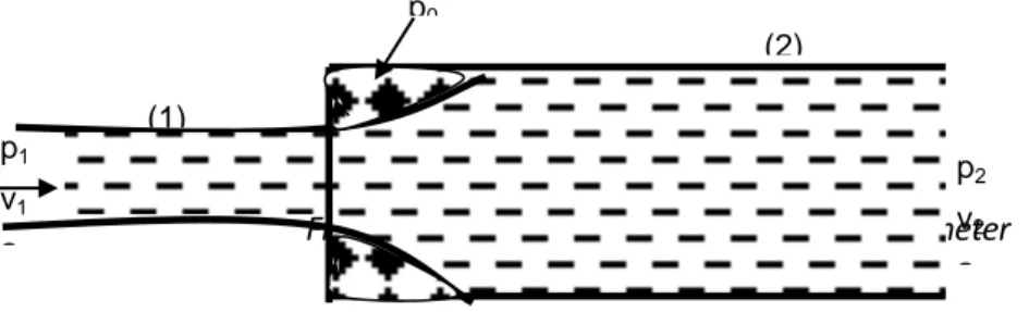
Fig. 3.2 shows a section of a pipe with an enlargement or increased diameter with flow
Fig. 3.2: Enlargement or Increased Pipe Diameter
A region of dead water occurring in which the pressure is P0 is shown, and at section (1) the pressure is P1,
velocity v1 and area a1 while at section (2) the corresponding values are P2, v2 and a2.
There is a change of momentum per second between sections (1) and (2) which is produced by the forces
due to the pressures P0, P1, and P2 – which have a resultant opposing motion.
Mass/sec. flow =
g
wWQ
…… 3.4
Where Q = discharge in (m3), w = unit wt. of liquid, and
g = acceleration due to gravity (m/s2).
Therefore,
Rate of change of momentum =
(
v
1v
2)
g
wQ
….. 3.5Force due to P2 opposing motion = P2a2
Force due to P1 opposing motion = P1a1
Force due to P0 opposing motion = -P0(a2 – a1)
Total force opposing motion = P2a2 – P1a1 – P0(a2 - a1)
The value of Po is found experimentally to be equal to P1, thus force opposing motion = a2(P2 – P1) = rate of
change of momentum
:. a2(P2 – P1) =
(
v
1v
2)
g
wQ
or since Q = a2v2 …. 3.6:. a2(P2 – P1) = ( 1 2) 2 2 v v g v a w =
g
v
v
v
g
v
g
v
v
w
p
p
2
)
(
2
2 1 222 1 2 1
2
…….. 3.7
If the hL = head lost at the enlargement, then by Bernoulli’s
Theorem,
h
Lg
v
w
P
g
v
w
P
2
2
2 2 2 2 1 1:. hL =
w
P
P
g
v
v
(
)
2
1 2 2 2 21
……… 3.8
Substituting for
w P
P2 1
from equation (3.7), we have
hL =
g
v
v
v
v
g
v
v
v
g
v
v
2
2
2
2
2
2
2 2 1 2 2 1 2 2 1 2 2 2 21
:. Head lost at enlargement = hL =
g v v 2 2 )
( 1 2
3.2 CHECK AGAINST OIL PIPELINE VANDALIZATION
For continuity of flow in any system of oil flow, the total amount of fluid e.g. oil entering the system
must equal the amount leaving the system. This occurs in case of uniform and steady flows. If the
continuity of flow relation did not apply, fluid would have been created or destroyed within the
system otherwise the pipeline would collapse or burst.
For NNPC oil pipeline where fluid is under continuity of flow, uniform, steady state flow or even
turbulent, if a sudden interruption occurs on the pipe line, (usually cutting off or drilling holes
by oil pipeline vandals), the law of continuity is immediately violated and any flow meters
mounted anywhere in the pipeline will detect this.
There are several types of flow meters for check of fluid flows in pipelines; a particular choice
depends on the function to perform and the type of fluid under consideration. Rate flow and
totalizing flow are the two general classes of measuring instrument [4].
The flow in pipes is usually measured by an orifice plate, by measuring the differential pressure
across it. Actually, the presence of the orifice alters the flow pattern in the pipe, and consequently, the
flow rate shown by the meter is not the same as it was before the orifice plate was installed [4&5].
The measured quantities can be transduced into voltage signals and are measured either by
conventional moving coil voltmeter or by potentiometer. It is a well-known fact, that
potentiometer is more accurate than moving coil voltmeter. This is so because moving coil
therefore the potential across its terminals is not quite the same as it was before the instrument was
connected to them [3]. Hence, the reading noted is in error, though very minute.
There are three or four phases in most of the measuring systems, each phase being made
up of a distinct component or group of components which perform required and definite steps
in measurement [4] viz (i) primary sensing device (ii) transducer (iii) intermediate modifying stage
(iv)terminating stage, (secondary) indicating instrument. Sometimes the primary sensing device
and the transducer are lumped to form a unit. The sensing device must be selective, being sensitive
to input variables to be measured and insensitive to other variables. The sensing device
provides "analogous" output with the help of the transducers after sensing the desired input. It is
the transducer that converts the input signals to other type of quantity which is more
useful and of course proportional to the input quantity.
Some basic detector - transducer types are [7&4]:
Mechanical: contacting spindles, spring mass, elastic device e.g. Boudon tube, proving ring etc.
Hydraulic - pneumatic detectors: buoyant float, orifice venturi vane, propeller etc.
Optical detectors: Photoelectric cell, photovoltaic cell, infra-red detectors, ultraviolet detectors and
photographic films.
Electrical: Nowadays electrical detectors are most commonly used such that they are used for
nearly all the applications. Some electrical sensing e lem e nt s a n d t ra n sd uc e rs are:
co ntac to rs , resistance, inductance, capacitance, piezo-electric crystal, thermocouple, moving
electrodes, streaming potential etc.
3.3 THE PISTON FLOWMETER
Of all the flow meters known, this type is commonly used in oil industries as it is used to measure
the flow of kerosene, gasoline, oil, tar and other clean petroleum -based liquids. The pipe sizes
of this instrument are normally between the range 7.6 - 12.7cm diameters. Piston flow meters
are commonly used to measure specific flow of materials and are specialized instruments.
Variable area flow meters of the piston type are used to transmit flow rate measurement to
indicating, recording or controlling equipment in the remote locations. And once, the flow
rate being measured is violated by the pipeline vandals, it triggers off signals to the indicating,
recording or controlling equipment at the far remote locations for actions to be taken. The
normally installed horizontally in a pipeline with the spring assembly pointing down [4].
3.4 ULTRASONIC FLOWMETERS
One of the most unusual developments to occur in flowmeter technology in recent year is the
application of ultrasonic measuring techniques. This technology is largely the result of several new
materials used in transducers and related development in pipe design. Measurements achieved by
this technique do not obstruct the flow path and can be achieved by portable instruments that are
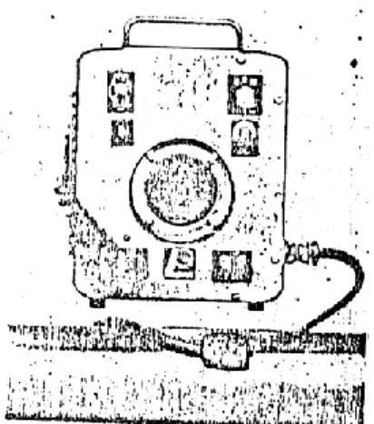
easily clamped on to a pipe at a moment’s notice. A representative clamp-on ultrasonic
flowmeter is shown below in fig 3.3. This flowmeter operates on the principle of sound
propagation in a liquid. The idea that changes in pressure travel in a liquid at the speed of sound
was employed in its development (dated back to days of sonar). In the flowmeter, sonic pulses are
generated by piezometric transducer which is responsible for converting electrical energy into
vibrating signal that is transmitted into a liquid as a pulsed wave. And when the pulse wave is
directed downstream into a flowing liquid, its speed or frequency is added to that of the flowing
stream. When the same signal is directed upstream, its frequency is decreased by the speed of the
stream.
Fig. 3.3: (a) An Ultrasonic Flowmeter (b) A simplification of ultrasonic flowmetering
principle.
3.4.1 OPERATIONAL STRUCTURE
In its simplest form, two opposing transducers are inserted into a pipeline at 450 angle. This angle
was found to be a convenient way of obtaining the average flow velocity along the path being
measured. In practice, ultrasonic Aulses of 1.25MHZ are radiated alternatively between the two
detector. An electrical signal is therefore developed alternately by the two transducers. However,
several billions of naira was lost in 2013 and 2014 by the NIPP in Nigeria because of the evil
perpetrations of the vandals. “When you think you are dealing with one or two blow holes on
these pipes, you end up dealing with a dozen of them”, Power Minister, Prof. Nebo on quote. So,
we need digital devices like the ultrasonic flowmeters that will be able to monitor and give us
up-to-date situation across the country.
Flow rate measurement of this instrument is based on the time difference that occurs between
the upstream and downstream signal propagation.
A beat frequency produced by mixing the output signals of each transducer together is
proportional to the average fluid velocity along the measured path. In effect, the speed or
frequency at which each transited pulse travels through the liquid is cancelled out, thus, yielding
only the frequency difference. As an example, if a pipe is full of liquid that is not flowing, the
downstream frequency might be 1.25MHz with the upstream frequency being equal to 1.25MHz.
The frequency difference in this case is 1.25MHz - 1.25MHz, or zero, which indicates no resulting
flow [10]. When a fluid flow occurs, the downstream pulse frequency could possibly increase in
value to 1,250,500Hz. The upstream frequency would likewise be influenced by the flow and could
cause corresponding decrease in valve to 1,249,5090Hz [10]. The resulting difference in frequency,
in this case, would be 1,250,500 – 1,249,400 or 1000Hz. This difference in frequency could be
equated to a flowrate of specific value. Any further increase in flowrate would yield a greater
difference in frequency and higher flowrate indication [10]. This frequency “difference signal” of
an ultrasonic flowmeter, is typically in the range of 50 to 100KHz. Note that this signal is usually
cleaned up and may be counted by a digital display instrument or it may be converted into
appropriate voltage or current analog values according to the design of the instrument.
The advantage of this instrument is great and depends mightily on the specific application. In
general, they are accurate within 0.5 percent of full scale; have linear ranges of 100 to 1, do not
obstruct the flow path, and can be adapted to pipe sizes from 0.635cm to 9.14m, and are
independent of flow temperature, density, viscosity and pressure. The major disadvantages are
initial cost and sensitivity to fluid composition with a high percentage of particles. The principle
3.5 CONCLUSION
Oil pipeline vandalizaiton is actually a "canker worm" eating deep into the national fabric and
must be fought both physically and materially. As the devastating blows rained on the oil workers at
the oil locations and immediate vicinities by the hoodlums and militants are st i l l b e i ng
c h e c ke d , fa r re m o te an d . o u t s k i r t s vandalizaiton of pipelines are soaring high and all hands
must be on deck to fight these anomalies.
REFERENCES
Douglas J. F. (1975). Solution of Problem in Fluid Mechanics Part 1' (1975) Page 74 - 80, 166 - 194.
Ranald V. G., (1976). 'Fluid Mechanics and Hydraulics' 2nd Edition (1976). Page 125 - 127.
Adams Hydraulics Limited 'Foundry and Engineering Workspace Holme Green' (1975) page 3 1 - 3 3 .
Eke J., Ndubuisi S., Nwosu A., (2004). Instrumentation and measurement techniques. EL'DEMAK,
Publishers (2004) and 'Materials on Flow Process; Mechanical and Industrial
Measurements'. Page 118 and 139; page 6 and 7 respectively.
Escritt L.B. (1978). Public Health Engineering Practice Volume II' page 93-95.
Bunches D. and Wilson F. (1975). Design and Operation of small Sewage Works' page 125 - 127.
Therja B. L., Theraja A. K., (2005). Electrical Technology. S, Chand and Company Ltd. Pages
376 - 451.
Edward H. (1972). Electrical Technology. English Language Society and Longman Group
Ltd., pages 731 -660.
Onoh G. N. (1999). Basic Electrical Engineering. Immaculate Publications Ltd, Enugu, Pages
363 – 401.
Technology in India (1994) IEEE Spectrum (March) pp. 43 – 47.