Final System Design Document
Washington, D.C. February 2009
DOCUMENT CHANGE HISTORY
Version Number
Date Description
V1.0 February 2008 Interim Release V2.0 February 2009 Final Version
Table of Contents
EXECUTIVE SUMMARY ... ES-1
1 POC SYSTEM DESIGN DOCUMENT OVERVIEW ...1
1.1 Document Objective ...1
1.2 Scope ...2
1.3 Document Overview ...2
2 POC SYSTEM DESIGN OVERVIEW ...3
2.1 System-wide Design Decisions ...7
2.2 NG9-1-1 POC Demonstration Key Components ...10
2.3 POC System Design Approach ...12
3 CALL ORIGINATION POC SYSTEM DESIGN ...13
3.1 Design Definition and Perspective ...13
3.2 Design Constraints and Considerations ...14
3.3 Call Origination Using IP UA (Laptop with SIP Clients, IP Wireless, IP Phones)—Design and Specifications ...14
3.4 Call Origination Using Cellular Phone—Design and Specifications ...16
3.5 Call Origination using Telematics UA—Design and Specifications ...17
3.6 Call Origination Using Legacy Wireline Device—Design and Specifications ...18
4 IP ACCESS NETWORK POC SYSTEM DESIGN ...19
4.1 Design Definition and Perspective ...19
4.2 Design Constraints and Considerations ...19
4.3 IP Routing Design and Specifications ...19
4.4 Location Acquisition and Validation—Design and Specifications ...22
4.5 Telephony Gateway Design and Specifications ...23
5 NG9-1-1 NETWORK POC SYSTEM DESIGN ...25
5.1 Design Definition and Perspective ...25
5.2 Design Constraints and Considerations ...26
5.3 NG9-1-1 IP Routing Design and Specifications ...26
5.4 NG9-1-1 Database Design ...27
5.4.1 Automatic Location Identification (ALI) ... 28
5.4.2 Mobile Positioning Center (MPC) ... 28
5.4.3 VoIP Positioning Center (VPC) ... 29
5.4.4 LoST ... 29
5.4.5 Emergency Provider Access Directory ... 34
5.4.6 Master Street Address Guide ... 34
5.4.7 Identity and Access Management (IdAM) ... 35
5.4.8 Business Rules ... 41
5.4.9 Call Record Database ... 44
6 NG9-1-1 PSAP POC SYSTEM DESIGN ...53
6.1 Design Definition and Perspective ...53
6.3 POC NG9-1-1 PSAP Design and Specifications ...53
7 POC NETWORK MANAGEMENT SYSTEM DESIGN ...56
7.1 Design Definition and Perspective ...56
7.2 Design Constraints and Considerations ...56
7.3 Network Management System Design ...57
8 NG9-1-1 SYSTEM DESIGN CONSIDERATIONS ...59
APPENDIX A—ACRONYMS ... A-1
APPENDIX B—GLOSSARY ...B-1
EXECUTIVE SUMMARY
The Next Generation 9-1-1 (NG9-1-1) Initiative is a research and development project funded by the US Department of Transportation (USDOT) to define the framework and plan to deploy Internet Protocol (IP)-based emergency communications across the nation. The project has helped to define the concept of operations, functional
requirements, and system architecture, and to develop a transition plan that considers implementation costs, values, and risks.
From a technical perspective, the project has been guided by its long-term goal: “To enable the general public to make a 9-1-1 ‘call’ (any real-time communication—voice, text, or video) from any wired, wireless, or IP-based device…” Additional important considerations included advancing call delivery, locating callers, and improving system functionality “through new internetworking technologies based on open standards.” The NG9-1-1 Initiative has helped demonstrate these principles throughout the project’s duration.
The NG9-1-1 Final System Design document is the culmination of the technical work of the NG9-1-1 Initiative. Starting with the NG9-1-1 Concept of Operations (CONOPS), the project team leveraged past work done in the public safety and standards
communities. After the CONOPS, the project developed both high-level and detailed requirements, an architecture analysis report, and the initial system design. These project artifacts served as the basis for the Proof of Concept (POC) Deployment Plan. Using the NG9-1-1 Architecture Analysis Report as a basis, the NG9-1-1 POC system design relies on commercial off-the-shelf (COTS), open source, and common
telecommunications and networking products used throughout the industry. Because of the limited project scope, the POC system design does not include all the components listed in the architecture (e.g., legacy systems); however, it does represent virtually all the “next generation” system design elements. During the POC demonstration, very little of the legacy technology was demonstrated because those systems are in place today. However, it is important to recognize that when NG9-1-1 is fully implemented, both legacy and next generation systems will likely need to run concurrently until the legacy systems can be replaced or retired.
While the NG9-1-1 POC demonstration was not envisioned as an operational
demonstration, the facilities and staff of five public service answering points (PSAP) were used during the testing of the POC. At no time during the tests were real calls used nor did the test system interrupt the operations of the 9-1-1 system. This configuration allowed demonstration of the NG9-1-1 architecture in a controlled environment by professional call takers.
A number of system-wide decisions were made during the design of the POC. For example, the POC used Session Initiated Protocol (SIP) as the signaling protocol for call establishment, routing, and termination. Although other signaling protocols exist, SIP was chosen because of its wide industry acceptance and support and open source status. Another example of a design decision was the use of SIP gateways as interfaces to the NG9-1-1 POC network to demonstrate a modular architecture corresponding to a more realistic deployment scenario. These decisions helped control the scope of POC to maintain a tight implementation schedule.
The NG9-1-1 POC demonstrated selected features of the NG9-1-1 requirements and system design, focusing on the three main components of emergency calling: call origination, call support/processing, and call termination at a PSAP (more commonly known as a 9-1-1 Center). Because IP-based calling is a key factor for NG9-1-1, the POC used IP devices and systems, in addition to more traditional methods (e.g., wireline and wireless telephones, and legacy devices sending Short Message Service [SMS] text messages).
To demonstrate the networking features of NG9-1-1, a standalone and secure POC network was designed and implemented. The network connected three laboratory facilities (Booz Allen Hamilton and Texas A&M and Columbia Universities), four PSAPs (Rochester, New York; King County, Washington; St. Paul, Minnesota; and Helena, Montana) and one statewide PSAP network (the State of Indiana). Each of these entities was connected via secure Generic Route Encapsulation (GRE) tunnels over Internet2 and a mix of AT&T’s Commodity Internet and Multi-Protocol Label Switching (MPLS) network.
Call Origination
During the POC, a variety of call origination scenarios were tested, including legacy Public-Switched Telephone Network (PSTN) telephones, cellular telephones (voice and SMS texting), third-party call centers (telematics systems), and IP User Agents (UA), including laptops with SIP clients, IP telephones, and IP wireless devices). These devices successfully demonstrated call initiation as the first step in the overall call delivery process. A mix of simulated and actual access service providers were used to show the various routes a call could take to reach the NG9-1-1 system.
Demonstration of call origination devices helped identify areas for future research, including conference server and video compression technology for multiparty conferencing to support the needs of video interpreting services for the deaf and hearing-impaired. In addition, the demonstration showed that SMS texting was an inferior technology to support emergency calling because of its inability to support
identification of callers’ location information and its inability to guaranteed delivery or receipt. Although citizens who call 9-1-1 today believe that being able to send SMS messages to 9-1-1 is a critical need, the technology was not designed or possibly ever intended for this type of important use. On a positive note, the design of the telematics use case and the maturity of that commercial technology provided positive results that may be seen in actual use before a full rollout of NG9-1-1.
IP Access Network
The POC’s IP access network provided location acquisition and validation, network routing, and SIP signaling functions. To simulate an IP access network, the test laboratory implemented devices to dynamically assign IP addresses, translate host names to IP addresses, acquire locations for test calls, and provide network security for the POC network and devices.
POC test calls entered the IP access network through telephony gateways (and were converted to SIP) or were natively based on IP. Once within the IP access network, the calls accessed location acquisition and call routing services. The call’s location was used to route the call, and it was forwarded out of an edge/ border gateway and onto the NG9-1-1 network.
NG9-1-1 Network
The primary function of the NG9-1-1 network was to identify the appropriate PSAPs based on the call origination information and to efficiently and accurately route the call while maintaining data integrity. Simulated databases of NG9-1-1 data were used to ensure that appropriate business rules were applied prior to routing the calls to the POC PSAPs. In the live NG9-1-1 network, the data will be decentralized and geographically distributed to maximize the stakeholders’ needs for reliability, availability, scalability, and serviceability.
One of the main components of the NG9-1-1 network will be the Location to Service Translation (LoST) discovery protocol. LoST maps civic and geospatial regions to services (in this case, emergency services providers.) During the NG9-1-1 POC, LoST was used to resolve which PSAP a UA should contact for emergency services. The LoST server used its database to perform a lookup based on the caller’s location and return the identification and contact information for the requested service.
NG9-1-1 PSAP
The primary role of the NG9-1-1 PSAP in the POC was to receive simulated 9-1-1 calls generated from a variety of call origination devices. As part of the POC, PSAP
equipment and infrastructure were deployed at several live PSAPs that provide 9-1-1 emergency services within their city, county, or state. The project team ensured that the daily operations of the PSAPs were not disrupted while conducting the POC tests. POC equipment deployed at the PSAPs was isolated from their live environments, and while call takers participated in the testing, no real 9-1-1 calls were taken using POC
equipment.
As part of the POC, the call taker’s graphical user interface software was developed to terminate the calls and perform typical call taker support functions. In the NG9-1-1 environment, the amount and types of data displayed were dramatically increased; however, the call taker participants were able to quickly adapt to the new software with only minimal orientation.
The NG9-1-1 Final System Design document describes the technical design of NG9-1-1 and the POC implementation specifically, and discusses the key considerations and constraints of NG9-1-1 system components. It also provides insight on items for consideration for further research into NG9-1-1 technology.
1 POC SYSTEM DESIGN DOCUMENT OVERVIEW
This document describes the system design for the Next Generation 9-1-1 (NG9-1-1) Proof-of-Concept (POC) demonstration task. The NG9-1-1 Concept of Operations (CONOPS), High-Level Requirements document, and Architecture Analysis report, serve as the basis for this document. These documents are available for download at the U.S. Department of Transportation’s (USDOT) NG9-1-1 website:
http://www.its.dot.gov/ng911.
The NG9-1-1 POC demonstration was envisioned to demonstrate potential next generation features of the 9-1-1 system. This included—
• Call origination using—
– Internet Protocol (IP) User Agents (UA) such as laptops with Session
Initiation Protocol (SIP) clients, IP phones, and IP wireless devices (Audio, Text, Data, and Video)
– Cellular devices with Short Message Service (SMS) (Audio, Text and Data) – Third-party call centers such as Telematics service providers (Audio and
Data)
– IP Video Relay Systems (VRS) for the deaf and hard-of-hearing community
(Text, Data, and Video)
• Call support and processing using—
– Standard IP access networks
– NG9-1-1 Network components such as Emergency Services Routing Proxy
(ESRP) and data gateways
– NG9-1-1 databases such as Business Rules, and Location-to-Service
Translation Protocol (LoST)
• Call termination at the Public Safety Answering Points (PSAP) using—
– IP Automatic Call Distribution (ACD) systems – IP phones and workstations
– Human machine interfaces
This POC System Design Document (SDD) focuses on the design of key functional components required to successfully demonstrate NG9-1-1 features and functionalities. It is envisioned that industry, research institutions, and other government agencies will continue to conduct research and development (R&D) activities to further develop and test NG9-1-1 components, both included and not included in the POC demonstration. 1.1 Document Objective
The objective of the POC SDD is to document the design of key NG9-1-1 components that were included in the POC demonstration.
1.2 Scope
The scope of the POC SDD includes developing a system design for the following NG9-1-1 POC demonstration functional components:
• Call origination, including legacy telephony, cellular devices with SMS capabilities, telematic systems, IP UAs and VRSs
• IP access network, including location acquisition and validation, and call routing
• NG9-1-1 Network, including LoST mapping and call routing
• NG9-1-1 databases, including Automatic Location Identification (ALI), LoST, Business Rules, and Call record database
• NG9-1-1 PSAPs, including call termination and call management. 1.3 Document Overview
The remaining sections of this document are organized as follows:
• Section 2—POC System Design Overview: Provides an overview of the NG9-1-1 POC system design components and describes the approach used to develop the POC SDD
• Section 3—Call Origination POC System Design: Describes the system design for originating NG9-1-1 calls using devices such as IP UAs (laptop, IP wireless devices, IP phones), cellular phones (handset with SMS), third-party call centers (telematics), and IP VRSs for the deaf and hard of hearing community
• Section 4—IP Access Network POC System Design: Describes the system design of the IP access network that was implemented in the Booz Allen Center for Network & Systems Innovation (CNSI) at One Dulles
• Section 5—NG9-1-1 Network POC System Design: Describes the system design of the POC NG9-1-1 network that was implemented in the Texas A&M
University (TAMU)/Columbia University test laboratories
• Section 6—NG9-1-1 PSAP POC System Design: Describes the system design of equipment that was deployed at the PSAPs for emergency call termination
• Section 7—Network Management System POC System Design: Describes the design of the network management system that was used in the POC for
monitoring the POC test-bed infrastructure and collecting system performance metrics
• Appendix A—Acronyms: Lists acronyms used in this document
• Appendix B—Glossary: Defines key terminology used in this document
• Appendix C—Source References: Provides a list of published documents that were referenced while developing this document
2 POC SYSTEM DESIGN OVERVIEW
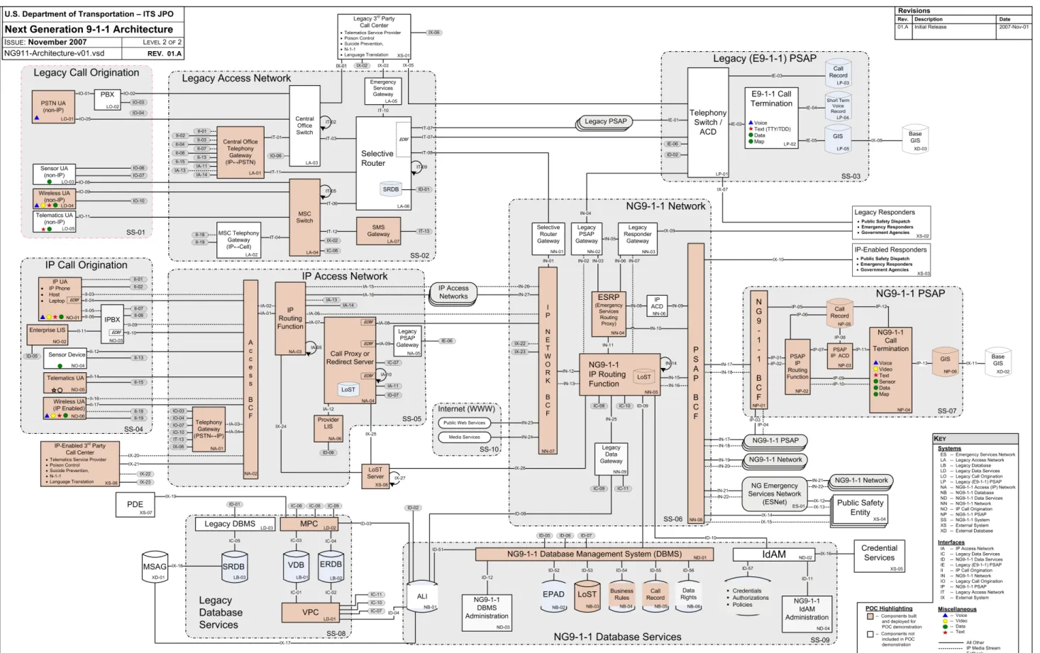
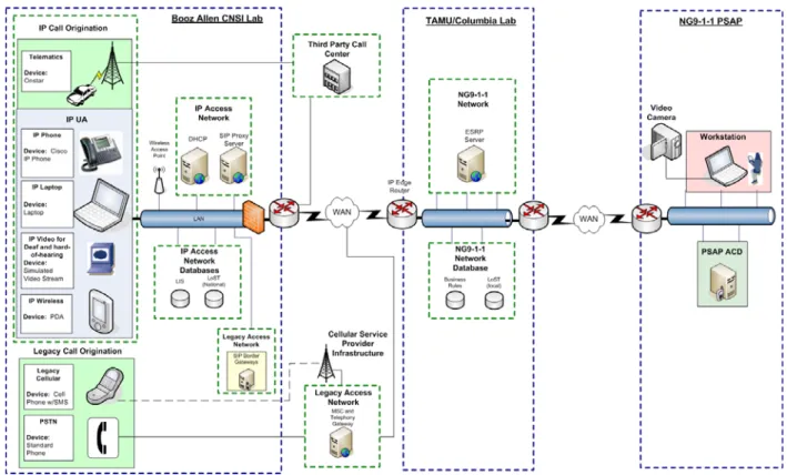
The NG9-1-1 POC system design was developed from the NG9-1-1 architecture defined during Task 1f. The design uses commercial off-the-shelf (COTS), open source, and commonly used telecommunications vendor products. However, the design does not include all components in the architecture. Figure 2.1 depicts the overall NG9-1-1 architecture, with highlighting to indicate components that were built and deployed for the POC demonstration. The NG9-1-1 Architecture Analysis Report provides detailed descriptions of all NG9-1-1 components and their respective interfaces.
The NG9-1-1 POC demonstration was not envisioned as an operational demonstration. At no time during the tests were real calls used; nor did the test system interrupt the operations of the 9-1-1 system. Rather, key components of the NG9-1-1 architecture were simulated and demonstrated in a controlled environment. End-to-end use cases, including call origination using legacy wireline telephony, cellular phones, third-party call centers (telematics), IP UAs and VRS for the deaf and hard-of-hearing community were developed and tested. Testing of these scenarios involved acquiring and
validating location information from location information systems, routing the calls to the simulated NG9-1-1 Network, performing location-to-service mapping (LoST), querying various NG9-1-1 databases, and finally routing the calls to the appropriate PSAP participating in the NG9-1-1 POC demonstration. Pre-selected call takers at the PSAPs received and responded to the simulated NG9-1-1 calls. Testing included
functional validation as well as the capture and analysis of various system performance metrics.
2.1 System-wide Design Decisions
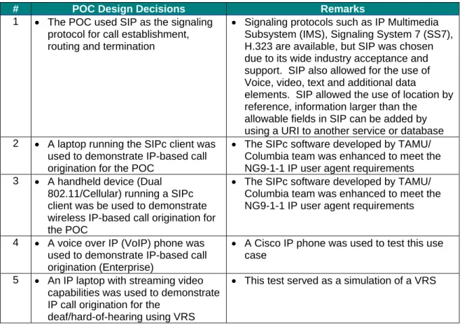
Table 2.1 lists the system-wide design decisions that were made over the course of the NG9-1-1 POC.
Table 2.1: System-wide Design Decisions
# POC Design Decisions Remarks
1 • The POC used SIP as the signaling protocol for call establishment, routing and termination
• Signaling protocols such as IP Multimedia Subsystem (IMS), Signaling System 7 (SS7), H.323 are available, but SIP was chosen due to its wide industry acceptance and support. SIP also allowed for the use of Voice, video, text and additional data
elements. SIP allowed the use of location by reference, information larger than the
allowable fields in SIP can be added by using a URI to another service or database 2 • A laptop running the SIPc client was
used to demonstrate IP-based call origination for the POC
• The SIPc software developed by TAMU/ Columbia team was enhanced to meet the NG9-1-1 IP user agent requirements 3 • A handheld device (Dual
802.11/Cellular) running a SIPc client was be used to demonstrate wireless IP-based call origination for the POC
• The SIPc software developed by TAMU/ Columbia team was enhanced to meet the NG9-1-1 IP user agent requirements
4 • A voice over IP (VoIP) phone was used to demonstrate IP-based call origination (Enterprise)
• A Cisco IP phone was used to test this use case
5 • An IP laptop with streaming video capabilities was used to demonstrate IP call origination for the
deaf/hard-of-hearing using VRS
# POC Design Decisions Remarks
6 • A legacy wireline emergency phone call was demonstrated by interfacing an analog phone with an IP
telephony gateway
• A Standard IP telephony gateway, such as Cisco’s Integrated Service Router, was used to perform the public switched telephone network (PSTN)-to-IP translation
7 • A Selective Router Database (SRDB) was not used for the POC
• Due to design decision #6, a legacy access network was not required, therefore, no selective router or SRDB was required 8 • Data Services using IP Sensor
Systems were not demonstrated in the POC
• An IP Sensor System can be considered another IP source. Demonstrating integration with a IP-based telematics system was deemed adequate to showcase this NG9-1-1capability
9 • IP call routing to legacy PSAPs was not demonstrated in the POC
• The POC environment did not include any legacy PSAP equipment. Therefore, call routing to legacy PSAPs was not demonstrated
10 • Identity and Access Management was not demonstrated during the POC
• Maintaining identities for administration of the NG9-1-1IP network is important. Mechanisms for providing identity and access to the NG9-1-1Network for Service Providers, PSAP Operators, Network Administrators, DB Administrators, and Data Access Rights for Users and Applications was not demonstrated but should be investigated in future NG9-1-1 efforts 11 • An MSAG database was not used
for the POC
• Given the current support for legacy call origination, there is no technical need for an MSAG database for POC.
• MSAG valid data was developed from participating PSAPs and then incorporated in the appropriate DB’s (LoST,Location Information Server [LIS], ALI/Mobile Positioning Center [MPC]/VoIP Position Center [VPC]) for the POC
12 • A Network Management System was deployed for POC but in a limited context
• A basic out-of-box Network Management product was deployed for the POC
• Integration occurred with all network devices (routers, switches, etc.) and servers (SIPd, LoST, etc.) residing on the NG9-1-1 Network
• Only limited monitoring and reporting was supported for the POC since, management of an IP-based network was not the main focus of the POC
13 • A LoST DB server resided in the Booz Allen CNSI and TAMU / Columbia test facilities. The Booz Allen CNSI LoST DB contained national level routing data and the TAMU LoST DB contained
state/county/local level routing data
• It was imperative that the hierarchical nature of LoST was tested during the POC because this mimics a practical implementation of the service in nationwide deployment
# POC Design Decisions Remarks
14 • The LIS/LoST data was considered pre-validated
• Because validating against a MSAG database was not possible because of integration challenges, pre-validated data was used for the POC demonstration 15 • An IP capable PSAP was
demonstrated in the POC
• The IP PSAP comprised of a router, switch, and firewall to support the POC use cases, and PSAP ACD and workstation to direct calls to the proper call taker within the PSAP and the workstation to answer and process the calls
• Standard IP routing protocols and T1 circuits provided the connectivity between the IP PSAP locations
16 • The Call Record Database was centrally managed within the NG9-1-1 Network
• To ease maintenance and acquisition of the data, the Call Record Database was hosted centrally
• In a real deployment, each PSAP would be responsible for maintaining its own call record Database. Additionally, the data would be aggregated and managed centrally within the NG9-1-1 network for redundancy purposes
17 • A series of SIP Border Gateways were deployed within the Booz Allen CNSI laboratory. Four gateways were used to support the POC use cases (Legacy, IP, Telematics, Cellular)
• The SIP gateways served as interfaces onto the NG9-1-1 Network for the various call sources/media streams
• This demonstrates a modular architecture corresponding to a more realistic
deployment scenario. It also eased
integration of call sources. Call sources can be added as an add-on component without affecting overall system reliability or up-time 18 • Dedicated T1 circuits were
provisioned between the PSAPs and the TAMU/Columbia test laboratories via Generic Route Encapsulation (GRE) tunnels
• Dedicated T1 circuits were used to support the POC demonstration traffic in order to avoid integration issues with the PSAPs’ production network
• Protecting the integrity of the system is of paramount importance for all involved
• Security must be multifaceted and
implemented at multiple levels. Using basic elements of IT-based security principles, GRE tunnels were employed to protect the POC environment and its participants 19 • Use of COTS equipment • With the exception of limited software developed specifically for the POC, all equipment used in the POC was COTS 20 • SMS converted to a SIP message • To deliver SMS messages the text was
converted to a SIP session. This allowed the user and the call taker to exchange messages. Since SMS is not a real time communication service, it is of limited value for requesting help in an emergency
The POC system leveraged components from the TAMU/Columbia NG9-1-1 prototype test-bed and expanded the system’s capabilities by including additional products and solutions to address the NG9-1-1 Tier 1 requirements identified under Task 1. The system design incorporated new technologies and applications to enhance the scope of the prototype thus demonstrating a broad set of features and functionalities of the NG9-1-1 System. Within the architectural framework, the POC system design uses existing call origination devices, IP access networks, third-party call centers, and legacy 9-1-1 systems and databases. Later sections of this document describe the details of the above mentioned design decisions.
2.2NG9-1-1 POC Demonstration Key Components
The NG9-1-1 POC demonstration includes the following key components:
• Call Origination
• IP Access Network
• NG9-1-1 Network
• NG9-1-1 Databases
• NG9-1-1 PSAPs.
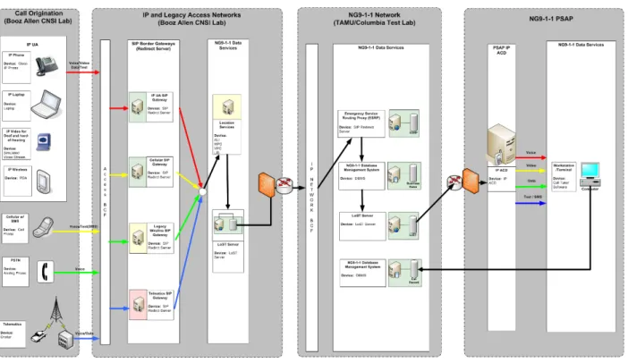
Figure 2.2, depicts a high-level design for the POC demonstration.
As shown, the Call Origination and the IP Access Network were hosted in the Booz Allen CNSI test laboratory (Herndon, VA), the NG9-1-1 Network was hosted logically between the TAMU (College Station, TX) and Columbia (New York, NY) test
laboratories and the five PSAPs housed the call termination equipment. T1 circuits were provisioned between the Booz Allen, TAMU, and Columbia test laboratories and the five PSAPs to provide interconnectivity between all functional components.
Test calls originated from the call origination endpoints and were routed through the IP Access Network to the NG9-1-1 Network. Components within the NG9-1-1 Network analyzed the call and identified the appropriate PSAP to route the call to based on the call stream parameters.
Figure 2.3 depicts the general flow of calls demonstrated in the POC.
Figure 2.3: Flow Diagram for Call Testing
Subsequent sections of this document outline, in detail, the design of each component and specify products that will be used for the POC demonstration.
2.3POC System Design Approach
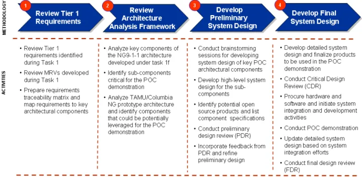
Figure 2.4 depicts the four-step approach that the Booz Allen Team adopted to develop NG9-1-1 POC SDD.
Figure 2.4: POC System Design Approach
of the
a mponents that could be leveraged from the prototype for the OC demonstration.
was
em design of each architectural component to be included in the POC demonstration.
As a first step, the Booz Allen Team reviewed the Tier 1 functional requirements developed during Task 1 and analyzed the Multidimensional Requirements Views (MRV) for various NG9-1-1 use cases. The MRVs are a layered representation functional requirements of the system. The team then analyzed the NG9-1-1
architecture developed during Task 1f to identify key components to be included in the POC demonstration. The team also conducted a gap analysis of the TAMU/Columbi prototype to identify co
P
Subsequently, several brainstorming sessions were held to develop the preliminary system design of key components. A Preliminary Design Review (PDR) discussion conducted to capture input on the initial system design. Input from the PDR was incorporated to develop the detailed system design for the CDR. Subsequent sections of this document outline the detailed syst
3 CALL ORIGINATION POC SYSTEM DESIGN
During the POC, a number of next generation call origination scenarios were tested. These include call origination using—
• Legacy PSTN Phones
• Cellular phones (Voice and SMS Texting)
• Third-Party Call Centers (Telematics Systems)
• IP UAs (including laptops with SIP clients, IP phones, and IP wireless devices) The demonstration focused on the delivery of the call information from these call origination devices to the NG9-1-1 PSAP using IP access and NG9-1-1 networks. 3.1Design Definition and Perspective
The architecture defined for the POC for originating calls was configured at the Booz Allen CNSI test laboratory. Figure 3.1 depicts the high-level design of the call
origination devices and illustrates how they were interfaced with other NG9-1-1 System components.
The call origination devices were located in the Booz Allen CNSI test laboratory. The calls were routed through an IP access network to the NG9-1-1 Network. Subsequent subsections provide detailed design and system specifications for each call origination device type. Each device type is explained in later sections.
3.2Design Constraints and Considerations
The call origination system design for the POC met all requirements for delivering IP and legacy calls to the NG9-1-1 Network. However, constraints limited successful demonstration of some features and functionalities. These constraints include—
• Integration Constraint: The NG9-1-1 routing paradigm requires a location for an emergency call to be presented with the call. Acquiring location information for the various call types (wireline, cellular, telematics, IP UA, and SMS) requires integration with a variety of external systems including ALI’s, MPC’s, VPC’s, and LIS’s. In some instances, such as SMS texting, the technology does not support location association or acquisition. Additionally, most commercial service providers would not allow access to their production locationing systems. This proved to be a significant integration and implementation challenge for the various call origination devices.
• Development Constraint: In order to overcome these location acquisition challenges many of the external location systems were simulated and developed specifically for the POC environment. For the POC an ALI, MPC, and SMS positioning system were developed this provide a much more controlled environment and limited the POC environment’s dependence on external systems.
3.3Call Origination Using IP UA (Laptop with SIP Clients, IP Wireless, IP Phones)— Design and Specifications
IP UAs were used to demonstrate IP voice, video, data and text to an NG9-1-1 PSAP. Figure 3.2 depicts the detailed system design of the IP UA call origination
Figure 3.2: IP UA Call Origination Design Overview
The following IP-based communications devices were integrated into the POC environment to demonstrate the capabilities of an IP-UA:
• Laptop with a SIP client
• IP wireless devices (PDA with SIP client)
• IP phones
• IP VRS with streaming video client
The laptop, IP phone, wireless access point, and IP VRS were connected to a standard Cisco 3500 series switch. A SIP client was loaded on the laptop, and calls were initiated from it. An IP camera was also connected to the laptop to demonstrate streaming video capabilities. The video streams generated using the camera demonstrated the ability of the NG9-1-1 system to support the deaf and hard-of-hearing community.
Unfortunately, due to constraints in the hardware the conference server used in the POC did not support three way video, although there are industry products available that support this capability. Additionally, the SIP client also provided the ability to support real-time texting. Users of the SIP client could establish an emergency instant message session with a PSAP call taker. The ability to simultaneously support voice, video and text demonstrated the diversity of communication mediums that the NG9-1-1 system could support. IP addresses were provided to the IP UAs using a Dynamic Host Configuration Protocol (DCHP) server located within the IP access network.
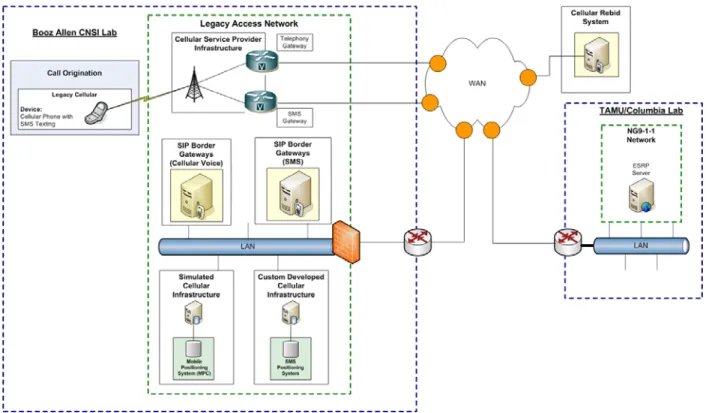
3.4Call Origination Using Cellular Phone—Design and Specifications
Emergency Cellular and SMS calls were demonstrated in the POC. A simulated MPC database was used to obtain the location information for cellular voice calls. The MPC today is located in the providing carrier’s network. Additionally, a SMS Positioning System was created to support location acquisition for SMS text messages. It should be noted that currently, there are no commercial systems available that locate senders of SMS. Given the mobile nature of cellular handheld devices the PSAP Call Taker was able to “Rebid” for an emergency caller’s location. During a “Rebid” the NG9-1-1 System would re-query the cellular handheld to acquire its updated position information. Figure 3.3 shows the various sub-components that were used to demonstrate the Cellular Voice and SMS use case for the POC demonstration.
Figure 3.3: Cellular Call Origination Design Overview
The POC used a standard cellular phone and cellular network to communicate to the NG9-1-1 POC test-bed network and deliver standard voice calls and SMS to the NG9-1-1 System. A cellular phone generated emergency voice calls or SMS text messages which were sent to a cellular service provider. The cellular service provider forwarded the cellular voice call or SMS data to the respective Cellular or SMS Border gateway. For Cellular voice, the border gateway acquired location for the cellular call from a simulated MPC. It then embedded this information in the call stream and forwarded the call onto the NG9-1-1 network to an ESRP. Similarly, for the SMS Use Case, the SMS border gateway received an SMS text message, converted the SMS
message to a SIP based message, acquired location from the SMS positioning system and then forwarded the message to an ESRP. IP was used to transport the voice and text information, and SIP will be used to establish and tear down the sessions. Once the call or text terminated at the PSAP the PSAP Call Taker had the ability to “Rebid” for the caller’s location. In order to provide this capability the Call Taker Software would query a Cellular Rebid System. The Rebid System would check its internal DB and determine if it knew the location of the requested cellular phone. If the Rebid System did not have current information on the location of the caller it would send a query to the cellular device asking for updated location information. Once the Rebid System obtained location information on the caller it would send this information back to the Call Taker.
3.5Call Origination using Telematics UA—Design and Specifications
The Telematics use case was demonstrated using a third-party call center service from OnStar. Figure 3.4, depicts the design used to demonstrate this use case.
Figure 3.4: Telematics Device Call Originations Design Overview As shown, the emergency crash notification data is sent to the telematics service provider’s call center using a cellular link. Within the telematics service providers call center the emergency call is converted to a SIP based call. The telematics service provider also embeds the location of the incident within the call stream and forwards
the call to the Telematics border gateway. The Telematics border gateway determines where to route the call by querying the LoST DB and then forwards it to an ESRP. The ESRP can query its business rules DB or obtain additional supportive data that may effect where the call is routed. As an example, an ESRP could determine the severity of the crash by obtaining additional Automatic Crash Notification (ACN) data. Based on the severity of the crash the ESRP may route the call to a different PSAP or
automatically conference in a third party such as an EMS or trauma center. The ESRP then forwards the call onto a PSAP where a call taker can handle the call. The Call Taker also has access to all ACN data and is presented this information on the Call Taker software.
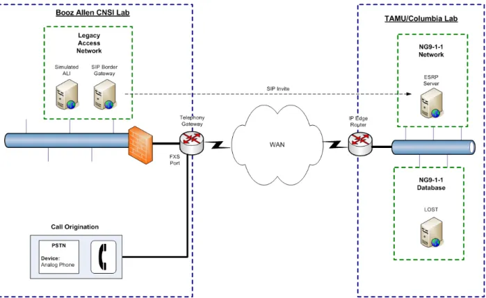
3.6Call Origination Using Legacy Wireline Device—Design and Specifications The POC demonstrated the ability to deliver a standard wireline emergency call
through an IP transport. Calls originating from the legacy PSTN phones were routed to the NG9-1-1 Network using a telephony gateway. The telephony gateway converted the call to SIP, acquired location from a simulated ALI DB and forwarded the call to a SIP border gateway server, which initiated a SIP session to the NG9-1-1 Network. Figure 3.5 depicts the design for this scenario.
4 IP ACCESS NETWORK POC SYSTEM DESIGN
The purpose of the IP access network in the POC is to provide location acquisition and validation, IP routing, and SIP signaling functions. The IP access network was
simulated at the Booz Allen CNSI test laboratory and hosted the following equipment: Dynamic Host Configuration Protocol (DHCP) Server to allocate IP addresses
dynamically to network devices, Domain Name System (DNS) Server to translate host names to IP addresses, Acquisition Servers (ALI, MPC, VPC, LIS), LoST, SIP Border Gateway Servers, Telephony Gateway, and routers. In addition, the IP access network routed the 9-1-1 calls to the NG9-1-1 Network.
4.1Design Definition and Perspective
The Booz Allen CNSI test laboratory was used to simulate and host the test-bed for the IP access network for the POC. In the POC, the IP access network provided the function of a service provider’s network and provided services such as DHCP, DNS, location acquisition, signaling, and IP routing. The IP access network served as the bridge between the IP call origination function and the NG9-1-1 Network and routed IP
packets using traditional WAN routing protocols such as Multiprotocol Label Switching (MPLS).
The DHCP service provided the IP address to the IP endpoints, and location acquisition and validation was performed using multiple mechanisms/databases such as ALIs, MPCs, VPCs, LISs, Global Positioning System (GPS) devices, Link Layer Discovery Protocol-Media Endpoint Discovery (LLDP-MED) and DHCP. A telephony gateway provided an interface for legacy wireline and cellular systems to connect to the IP access network. The telephony gateway converted incoming legacy technologies into SIP based calls. SIP signaling was used to transport the call and its associated call stream information (location, call type, supplemental data links, etc.) to the NG9-1-1 Network. 4.2Design Constraints and Considerations
In a real-world implementation of the NG9-1-1 architecture multiple networks would serve as the IP access network. For the POC, the IP access network was simulated solely within the Booz Allen CNSI test laboratory. In addition, implementation of location acquisition services would vary by service provider and would depend on the technologies that service provider supported (legacy wireline, cellular, VoIP, SMS, telematics, sensor data, etc.) Although the POC tested and demonstrated several different types of location acquisition mechanisms, some of these systems (ALI, MPC, SMS) were simulated in order to ease integration and scheduling constraints.
4.3IP Routing Design and Specifications
The NG9-1-1 System relied on standard protocols and best practices for IP routing of converged service networks. All voice, video, and data traffic was embedded in IP
packets and transported across the IP access and NG9-1-1 networks. Since there was limited traffic on the POC network, no priority or QOS mechanisms were utilized.
Figure 4.1: IP Routing Within IP Access Network Overview
Figure 4.1 depicts a high-level design of IP routing within the IP access network for the POC. Later sections depict the routing of specific types of user devices. All incoming emergency calls regardless of technology (wireline, cellular, telematics, IP UA, SIP) were converted to IP at a gateway. Once the call was converted to IP it could be routed just as any other standard IP packet across the POC network. Calls entered the IP access network through telephony gateways or were natively based on IP. Once within the IP access network the IP calls accessed location and call routing services. Once it was determined where to route the call, the call was forwarded out of an edge/border gateway across the WAN via Virtual Private Network (VPN) and onto the NG9-1-1 network. Traditional WAN routing protocols such as MPLS and ATM were used to route the IP packets across the IP Access and NG9-1-1 Networks. The IP access
network, NG9-1-1 network, and PSAPS were connected using GRE Tunneling to create a VPN environment. Within the LAN environments standard switching mechanism were utilized to route the IP calls.
IP routing within the POC environment was performed using industry standard Cisco routers. Cisco 2821 routers were used to route IP packets from the IP Call Origination sources to the NG9-1-1 PSAP. The Cisco 2821 router was chosen because it is capable of
supporting T1 WAN interfaces and SIP and can support various security features such as VPNs.
The security function of the IP access network includes a firewall feature-set. For the POC, Cisco ASA5505-K8 was used to provide this function. Appropriate ports were opened on the firewall to enable end-to-end secure connectivity. Logs from the firewall and other network devices were sent to the Syslog server to log alarms and alerts. The Cisco ASA5505-K8 also terminated VPN connections to the NG9-1-1 Network’s edge router.
For the POC, SIP signaling was used for session establishment and tear down. All call origination sources were converted to SIP and therefore could be handled similarly through the system. Figure 4.2 below depicts how a SIP session was established and terminated within the POC environment.
Figure 4.2: End-to-End SIP Session
For the POC all call origination sources (wireline, cellular, telematics, and SMS) were converted to a SIP based call. It should be noted that the IP UA’s (IP phones, IP wireless devices, and SIP clients) natively supported SIP. Upon instantiation, the SIP call was initially registered by the SIP Border Gateway Server located within the IP access network. If it was not already contained within the SIP Invite, the SIP Border Gateway used the Caller’s Information to obtain location information for the caller. Various Location Acquisition Systems were used depending on the type of call. From the location information the SIP Border Gateway queried a LoST Server to determine which PSAP location the call should be routed to. The SIP Border Gateway embedded this information within the SIP invite and forwarded it to the appropriate ESRP located
within the NG9-1-1 Network. The ESRP then queried another LoST Database to determine the appropriate PSAP to forward the SIP invite to. The PSAP IP ACD received the incoming SIP Invite, terminated the invite, and forwarded the call to the first available and most capable Call Taker. The Call Taker’s Workstation and the Call Origination Device then establishes a two-way media session that can contain voice, video and/or data depending on the capabilities of the caller and call taker. Once the Call completed and the needs of the Caller were addressed the call was torn down using a similar process of SIP BYE messages.
4.4Location Acquisition and Validation—Design and Specifications
For the POC, location information was acquired in numerous ways. The most simplistic use case required that the Call Origination device itself acquire location. This was demonstrated using the SIP client software. The SIP client software was able to interface with GPS, DHCP Servers and LLDP-MED compatible switches.
For most technologies location could not obtain by the device itself as was the case for legacy wireline, cellular, telematics, and IP Phones. For the legacy wireline, cellular and SMS devices the call was converted to SIP and forwarded into the network with no location information. When the call arrived at a SIP Border Gateway, the Border Gateway would determine what type of call it was and query its respective network location information system. For example, for a wireline call the SIP Border Gateway would query a simulated ALI DB. For cellular and SMS calls the SIP Border Gateway would query an MPC or SMS Positioning System respectively.
For telematics calls and IP Phones a network LIS proxy was used to acquire location. As these calls traversed the IP Access network they passed through an LIS proxy device which automatically embedded location information into the call stream. Figure 4.3 shows how location acquisition was executed for the various call types in the POC demonstration.
Figure 4.3: Location Acquisition and Validation Overview For the POC, all caller location information was assumed to be pre-validated.
Therefore, the location information was not validated for proper street number ranges or street names. A typical location validation process involves sending a query to an official MSAG DB. MSAGs are hosted and administered either directly by a 9-1-1 service provider or outsourced to a third-party vendor, this was not possible for the POC due to scheduling constraints.
4.5Telephony Gateway Design and Specifications
The function of the telephony gateway in the POC was to connect legacy PSTN and Cellular devices to the IP access network. Figure 4.4 depicts the high-level
IP Access Network
PBX Analog Phone
Telephony Gateway (Cisco VOIP Router) IP Analog
Legacy Network
Cellular
Figure 4.4: Telephony Gateway Design
Analog wireline and cellular phones were connected through their respective service providers to the telephony gateway, which performed the analog-to-IP conversion, encapsulated voice traffic into IP packets, and forward them to the IP access network.
5 NG9-1-1 NETWORK POC SYSTEM DESIGN
The primary function of the NG9-1-1 Network is to identify appropriate PSAPs based on the call origination information and to efficiently route the call to them while
maintaining data integrity. Several simulated next generation databases included in the design were used to streamline this process and ensure that appropriate business rules were applied prior to routing the calls to the PSAP.
The NG9-1-1 Network test-bed for the POC was hosted at the TAMU/Columbia laboratories. The sub-components included in the design were—
• ESRP
• LoST server
• Identity Management Database (including Data Rights)
• Business Rules Database
• Call Record Database.
5.1Design Definition and Perspective
The NG9-1-1 Network for the POC is designed using standard Open System
Interconnect (OSI) architecture. At the network layer, T1 circuits were used to provide the WAN connectivity to the PSAPs. IP WAN routers connecting to the dedicated T-1s within the TAMU and Columbia laboratories routed the calls to the appropriate PSAPs. A network designed as an IP overlay is a cost effective method of building a WAN to support the POC Layer 3 functions of the POC. The entire NG9-1-1 POC network was designed to be scalable and employed a WAN architecture to focus on IP delivery across the network. This design created a hierarchical framework to allow multiple services to access the network. The T-1 network using IP creates a common interface to the various devices and technologies associated with the POC.
The NG9-1-1 Network also used an ESRP. The ESRP made all the call routing decisions within the POC network. The ESRP received location information from the NG9-1-1 databases and forwarded the call and data to the IP WAN for routing the call to the correct PSAP.
The NG9-1-1 Network used SIP signaling to terminate calls. In the POC, the network provided bandwidth and transport facilities that allowed the delivery of the calls across the WAN to one of the PSAPs. All database functions were centrally located at the TAMU/Columbia test facilities.
5.2Design Constraints and Considerations
The NG9-1-1 Network design was based on a hub spoke architecture in which the Booz Allen and Columbia labs and PSAP all connected to the TAMU test laboratory. To maintain integrity of the data over the WAN, VPNs were configured using GRE tunnels. However, the GRE tunnels limited the use of dynamic routing protocols over the WAN.
Standards for several NG9-1-1 databases such as Data Rights and Business Rules do not exist today and had to be custom developed.
5.3NG9-1-1 IP Routing Design and Specifications
The IP routing within the POC NG9-1-1 Network was performed by the WAN edge routers located at the TAMU/Columbia test laboratories. Based on the call stream parameters, the ESRP routed the call data to the appropriate PSAP. Figure 5.1 depicts, at a high-level, how routing was executed within the NG9-1-1 Network.
VPN tunnels configured on the WAN edge routers at the TAMU/Columbia test labs encrypt and route the IP packets to the appropriate PSAP. If the target PSAP is unavailable, then the call was dynamically routed to the backup PSAP. SIP signaling was used to establish SIP calls between the ESRP and the IP ACD server located at the PSAPs.
5.4NG9-1-1 Database Design
Databases are a key component of the NG9-1-1 POC System Architecture. Databases store a variety of data and enable numerous system functions on the NG9-1-1 Network. Given the functional diversity of the data, geographically distributed nature of the network, decentralized operation of the stakeholders, and stringent emergency service requirements for reliability, availability, scalability, and serviceability, each database is designed uniquely to serve its specific function.
There is also a need for the NG9-1-1 Network to integrate with a variety of legacy databases to support emergency services for older communications systems. These legacy databases may eventually be phased out as communication systems shift from analog to digital mode, as control methods change, or as federal policy mandates. In addition, these databases were appropriately scaled with hardware, software, and network connectivity based on expected transactional loads and desired use cases for the POC. Figure 5.2 depicts the high-level overview of the NG9-1-1 and legacy
Figure 5.2: NG9-1-1 Databases Overview
For conciseness, only those databases implemented and/or simulated for the POC were documented in the subsequent sections.
5.4.1 Automatic Location Identification (ALI)
For the POC the ALI DB was simulated using an IP addressable relational database. An ALI Database provides caller location, subscriber name, Call Type related data, and other ALI data items to the call stream when a legacy 9-1-1 call enters the NG9-1-1 Network. This data was then used to support routing of the call to the appropriate PSAP and to display caller information to the call taker.
Because of technical complications and time and budget constraints, an IP-accessible LIS approach was used for the POC, with simulated ALI data populated into the LIS. The National Emergency Number Association (NENA) Data Exchange Standard 02-010 provides the content and format of the data required to be used to populate the ALI data records. This document can be downloaded from the following site:
http://www.nena.org/media/files/02-010_20070717.pdf 5.4.2 Mobile Positioning Center (MPC)
MPCs are typically operated for cellular carriers by vendors and are based on
assignment services for cellular 9-1-1 calls to E9-1-1 systems. Dynamic ALI update data, including the caller’s location, are provided to ALI servers so that full ALI can be
provided to PSAPs during a cellular 9-1-1 call. The interface between ALI servers and MPCs is typically, but not exclusively, known as an E2+ interface and is a specialized protocol for this application.
The E2+ interface supplies the mobile cellular caller telephone number, the current estimated location of the handset, and other ALI equivalent data for the cellular service type. The E2 interface must be able to handle queries and responses for these various network configurations. That is, both ALI servers (typically configured as a redundant pair) must be capable of querying both MPCs in a network configuration where both operate as redundant nodes. Transmission Control Protocol (TCP)/IP and Transaction Capabilities Applications Part (TCAP) are recommended, and more specifics are
available in NENA Technical Standard 05-001 at:
http://www.nena.org/media/files/05-001_20031202.pdf
For the POC, the cellular data normally provided from an MPC was acquired from a simulation of the MPC functions using a static relational database. A second method of dynamic location acquisition was tested using a third party software loaded on the cellular handset.
5.4.3 VoIP Positioning Center (VPC)
VPCs are typically operated for VoIP by Internet service providers and, based on previously stored subscriber data, provide routing code assignment services for VoIP 9-1-1 calls to E9-1-1 systems, and dynamic ALI update data, including the caller’s location, to ALI servers so that full ALI can be provided to PSAPs during an
Internet-based VoIP 9-1-1 call. The interface between ALI servers and VPCs is typically, but not exclusively, known as an E2+ interface, and is a specialized protocol for the similar cellular application. The E2+ interface supplies the fixed or nomadic VoIP caller telephone number, the stored current `registered address’ of the handset, and other ALI equivalent data for the VoIP service type. More specifics are available in NENA
Technical Standard 05-001 at: http://www.nena.org/media/files/05-001_20031202.pdf For the POC interfacing with a VPC was not possible, the VoIP subscriber data
normally provided by a VPC was simulated. 5.4.4 LoST
LoST is a discovery protocol centered on mapping civic and geospatial regions to services. For the NG9-1-1 POC, LoST was used to resolve which PSAP a UA should contact for emergency services. LoST queries contain either civic or geodetic location information and traverse from a LoST client to a LoST server. The LoST server uses its database to map the input values to one or more Uniform Resource Identifiers (URI)
and returns those URIs to the LoST client. If the server cannot resolve the query itself, it may, in turn, query another server or return the address of another LoST server,
identified by a LoST server name. For the POC, LoST servers resided at the Booz Allen CNSI test laboratory and the TAMU lab to simulate location acquisition. Therefore, LoST queries were resolved either recursively or iteratively. Figure 5.3 depicts the LoST function.
Figure 5.3: LoST Function For the POC, the following design assumptions were made:
1. LoST clients must discover LoST Servers by using either DHCP or manual configuration.
2. The LoST database is populated with datasets (civic and geodetic) and is managed by an external authority.
3. It is the responsibility of the LoST client to query, cache, and maintain service mappings. A LoST client will not be notified if service mappings defined within the LoST databases change.
4. The datasets within the geographically distributed LoST databases will not be automatically synchronized.
As depicted in Figure 5.4, the LoST Database contained two tables that support civic and geospatial service resolution. The “civic_us” table stored civic information as defined in the Internet Engineering Task Force (IETF) Presence Information Data Format–Location (PIDF-LO) standard and associates it with a given service URI. The “geo_us” table stored geospatial information defined by a geometry object. The database was enabled with geographic information system (GIS) extensions that support geospatial queries.
Figure 5.4: LoST Database Structure
Tables 5.1 and 5.2 list the structure of the civic and geospatial tables within the LoST Database.
LoST Civic Table
Table 5.1: LoST Civic Table Structure Table Description
Name civic_us
Description This table maps a civic boundary defined by a PIDF-LO Profile to a service URI.
Parameter Type Values/Restrictions
Id Integer Primary Key—must be unique
Description unique identifier
Country Character Length—2 characters
Description two-letter ISO 3166 country code
a1 Character Length—50 characters
Description national subdivisions (state, region, province, prefecture)
a2 Character Length—50 characters
Description county, parish, district (IN)
a3 Character Length—50 characters
Description city, township
Description city division, borough, city district, ward, etc.
a5 Character Length—50 characters
Description neighborhood, block
a6 Character Length—50 characters
Description Street
Prd Character Length—10 characters
Description leading street direction
Pod Character Length—10 characters
Description trailing street suffix
Sts Character Length—10 characters
Description street suffix
Hno Character Length—10 characters
Description house number (numeric part only)
Hns Character Length—10 characters
Description house number suffix
Lmk Character Length—50 characters
Description landmark or vanity address
Loc Character Length—10 characters
Description additional location information
Flr Character Length—10 characters
Description Floor
Nam Character Length—50 characters
Description name (residence, business, or office occupant)
Pc Character Length—10 characters
Description postal code hno_l Integer
Description low in house number range hno_h Integer
Description high in house number range
hno_oe Character Length—1 character
Description odd/even indicator
Service Character Length—50 characters
Description service Uniform Resource Name (URN)
Name Character Length—50 characters
Uri Character Length—256 characters Description SIP Uniform Resource Locator (URL) of a service
modified Timestamp
Description timestamp when the record is modified is_default Boolean
Description indicator whether the record is for a default route
LoST Geospatial Table
Table 5.2: LoST Geospatial Table Structure
Table Description
Name geo_us
Description This table maps a geospatial boundary defined by Geography Markup Language (GML) to a service URI.
Parameter Type Values/Restrictions
Id Integer Primary Key—must be
unique Description unique identifier
Service Character Length—50 characters
Description service URN
display_name Character Length—50 characters Description service description for display
Uri Character Length—256 characters
Description SIP URL of a service Modified Timestamp
Description timestamp when the record is modified
the_geom Geometry Multipolygon
Description the polygon that represents the service boundary
LoST Database Interface
To accommodate the diverse set of LoST clients and support higher level functionality defined by the LoST protocol, the LoST Database is abstracted from LoST clients with a web interface. This interface is implemented by the LoST Web Server using HTTP and HTTPs protocol exchanges. For the POC, the queries listed in Table 5.3 will be
supported. For more detail on the format and structure of the queries request/responses refer to the “IETF LoST Standard.”
Table 5.3: LoST Database Interface
LoST Interface
Interface Name LoST Interface ID-53 Interface Design Doc IETF LoST draft Standard
Description This interface allows a client to query the LoST database for Service Names, Service URIs, and Service Boundaries using a variety of XML-based queries defined below. Applications Protocol LoST Protocol (XML) over HTTP(S)
Transport/Network Protocol TCP / IP
Supported LoST Queries Description
<findService> and <findServiceResponse>
A LoST client can retrieve service contact URIs based on location information and a service identifier.
<getServiceBoundary> and <getServiceBoundaryResponse>
A LoST client can obtain a service boundary. <listServices> and
<listServicesResponse>
A LoST client can find out which services a LoST server supports.
<listServicesByLocation> and <listServicesByLocationResponse>
A LoST client can determine which services are available for a specific location region. 5.4.5 Emergency Provider Access Directory
EPAD planned capabilities, including data or digital rights management, were not expected to be ready in alpha design form until mid-2008. Data rights management functions was not part of the current EPAD prototype. EPAD functionality was
featured in the LoST database for the POC demonstration. The proposed data structure of EPAD can be downloaded from the following link:
http://www.comcare.org/uploads/EPAD%20Technical%20Implementation%20Guide %20v1%202%2010242005.pdf
5.4.6 Master Street Address Guide
Current MSAG functions, including definition of valid address ranges, streets and communities, address validation data provision to other functions based on the above definitions, and the relationship of street segments and communities to public safety jurisdictions and their assigned routing codes (Emergency Service Number [ESN]) will be structured and managed differently in NG9-1-1. These types of data will appear as GIS data layers, associated with the LoST databases. As a result, the MSAG data and related physical databases were not accessed directly by NG9-1-1 functions or POC equipment.
MSAG data, however, was needed to set up the address validation and routing relationships in the POC databases, as structured under NG9-1-1 definitions. The appropriate MSAG data content was acquired for the 9-1-1 Authorities involved in the POC. The contents of a typical MSAG data record are as shown in the NENA 02-010
Data Exchange document, which is available at:
http://www.nena.org/media/files/02-010_20070717.pdf 5.4.7 Identity and Access Management (IdAM)
The IdAM databases provide identity, authentication, and authorization for users and administrators of the NG9-1-1 System. Given that the NG9-1-1 Network emphasizes an IP-based paradigm, the network, as well as its users and resources, must be protected with safeguards similar to those currently implemented in most enterprise IP-based networks today. Figure 5.5, depicts an overview of the IdAM databases.
Figure 5.5: Identity and Access Management Databases
In the context of IdAM, the term user defines any entity that uses the NG9-1-1 Network. User is a generic term and captures a variety of entities, including system
administrators, software clients, Internet service providers, and PSAP operators. It should be noted that these entities can be both animate (people) and inanimate objects (applications, devices, connections, etc). The purpose of the Identity database is to maintain and manage these identities. Due to the significant level of effort required to implement IdAM, it was not included in the scope for the POC.
Complementary to users, the term resource defines objects within the NG9-1-1 Network that perform a specific function (routing, switching, etc.) or provide a piece of
information (database records) to users. Users use resources to execute a defined activity or use case. Examples of resources include communication infrastructure such as routers, switches, and firewalls; servers that support IP telephony or applications; or database management systems with their associated databases. The Identity database is also responsible for tracking and maintaining the identity of NG9-1-1 resources.
The Data Rights database provides authorization capabilities for the NG9-1-1 System. The Data Rights database is responsible for maintaining a mapping between users and resources. When a user attempts to access a resource, the resource queries the Data Rights database to ensure the user has appropriate privileges. It is usually the responsibility of an IdAM Administrator to maintain a user’s roles and privileges within the system.
It is envisioned that in order to move to an IP-based NG9-1-1 Network, an Enterprise Network Operations Center (ENOC) will have to be created to manage IdAM
functionality. Given the geographically distributed and loosely coupled nature of the NG9-1-1 Network, IdAM functionality will likely be implemented in a federated manner. Given that the NG9-1-1 POC’s main focus is emergency operations and use cases, a simplistic IdAM approach was demonstrated for the POC. However, this topic should be reevaluated in a nationwide operational deployment of the NG9-1-1
Network.
Figure 5.6: IdAM Database Structure Overview
It should be noted the defined IdAM schema is strictly conceptual in nature. There are a variety of standards-based vendor products that implement IdAM functionality. This schema captures the basic functionality of an IdAM system. Structure for the user, role, resource, authorization, and trust tables are shown below.
User Table
Table 5.4: User Table Structure
Table Description
Name User
Description This table stores the properties and credentials of an NG9-1-1 Network User.
Parameter Type Values/Restrictions
Description unique identifier for an NG9-1-1 Network User
Password Character Length—50 Characters Description password for the User (Provides Single Sign On (SSO)
capability)
organization_dn Character Length—50 Characters Description domain to which the User belongs
Roleid Integer Length—50 Characters
Description role of the User (e.g., DB Admin, Sys Admin, PSAP Call Taker etc.)
first_name Character Length—50 Characters Description first name of the User
middle_name Character Length—50 Characters Description middle name of the User
last_name Character Length—50 Characters Description last name of the User
Telephone Character Length—50 Characters Description POTS telephone number of the User
Email Character Length—50 Characters
Description e-mail address of the User
sip_addr Character Length—50 Characters
Description SIP address of the User
addr1 Character Length—50 Characters
Description address of the User
addr2 Character Length—50 Characters
Description supplemental address information for the User
City Character Length—50 Characters
Description city in which the User resides
State Character Length—50 Characters
Description state in which the User resides
Zip Character Length—50 Characters
Description zip code in which the User resides
Country Character Length—50 Characters
Role Table
Table 5.5: Roles Table Structure
Table Description
Name Role
Description This table stores the defined NG9-1-1 System Roles.
Parameter Type Values/Restrictions
roleid Integer Primary Key—must be unique Description unique identifier for an NG9-1-1 System role
name Character Length—50 Characters
Description Text Tag identifying the role (e.g., Sys_Admin, DB_Admin, etc.)
Resource Table
Table 5.6: Resource Table Structure
Table Description
Name Resource
Description This table stores the properties and credentials of a NG9-1-1 Resource.
Parameter Type Values/Restrictions
Resourceid Integer Primary Key—must be unique Description unique identifier for an NG9-1-1 Resource
Password Character Length—50 Characters Description password for the Resource
organization_dn Character Length—50 Characters Description domain the Resource belongs to
asset_tag Character Length—50 Characters Description Asset Tag of the Resource for tracking purposes
addr1 Character Length—50 Characters
Description address of the Resource
addr2 Character Length—50 Characters
Description supplemental address information for the Resource
City Character Length—50 Characters
Description city the Resource resides in
State Character Length—50 Characters
Description state the Resource resides in
Zip Character Length—50 Characters
Description zip code the Resource resides in
Country Character Length—50 Characters